VOLKSWAGEN PASSAT 1997 B3, B4 / 3.G Service User Guide
Manufacturer: VOLKSWAGEN, Model Year: 1997, Model line: PASSAT, Model: VOLKSWAGEN PASSAT 1997 B3, B4 / 3.GPages: 369, PDF Size: 12.33 MB
Page 11 of 369
Downloaded from www.Manualslib.com manuals search engine 00-5
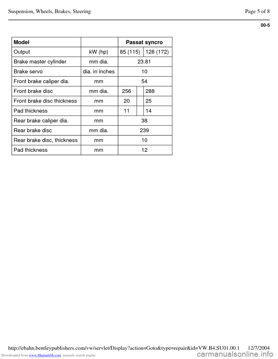
Model
Passat syncro
Output kW (hp) 85 (115) 128 (172)
Brake master cylinder mm dia. 23.81
Brake servo dia. in inches 10
Front brake caliper dia. mm 54
Front brake disc mm dia. 256 288
Front brake disc thickness mm 20 25
Pad thickness mm 11 14
Rear brake caliper dia. mm 38
Rear brake disc mm dia. 239
Rear brake disc, thickness mm 10
Pad thickness mm 12 Page 5 of 8Suspension, Wheels, Brakes, Steering12/7/2004http://ebahn.bentleypublishers.com/vw/servlet/Display?action=Goto&type=repair&id=VW.B4.SU01.00.1
Page 12 of 369
Downloaded from www.Manualslib.com manuals search engine 00-6
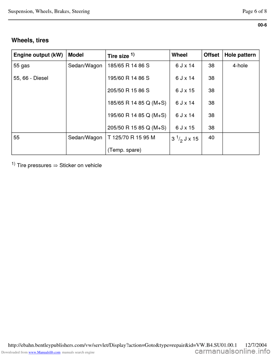
Wheels, tires Engine output (kW)
Model
Tire size 1)
Wheel
Offset
Hole pattern
55 gas
55, 66 - Diesel Sedan/Wagon 185/65 R 14 86 S
195/60 R 14 86 S
205/50 R 15 86 S
185/65 R 14 85 Q (M+S)
195/60 R 14 85 Q (M+S)
205/50 R 15 85 Q (M+S) 6 J x 14
6 J x 14
6 J x 15
6 J x 14
6 J x 14
6 J x 15 38
38
38
38
38
38 4-hole
55 Sedan/Wagon T 125/70 R 15 95 M
(Temp. spare) 3 1
/
2 J x 15
40 1)
Tire pressures Sticker on vehicle Page 6 of 8Suspension, Wheels, Brakes, Steering12/7/2004http://ebahn.bentleypublishers.com/vw/servlet/Display?action=Goto&type=repair&id=VW.B4.SU01.00.1
Page 13 of 369
Downloaded from www.Manualslib.com manuals search engine 00-7
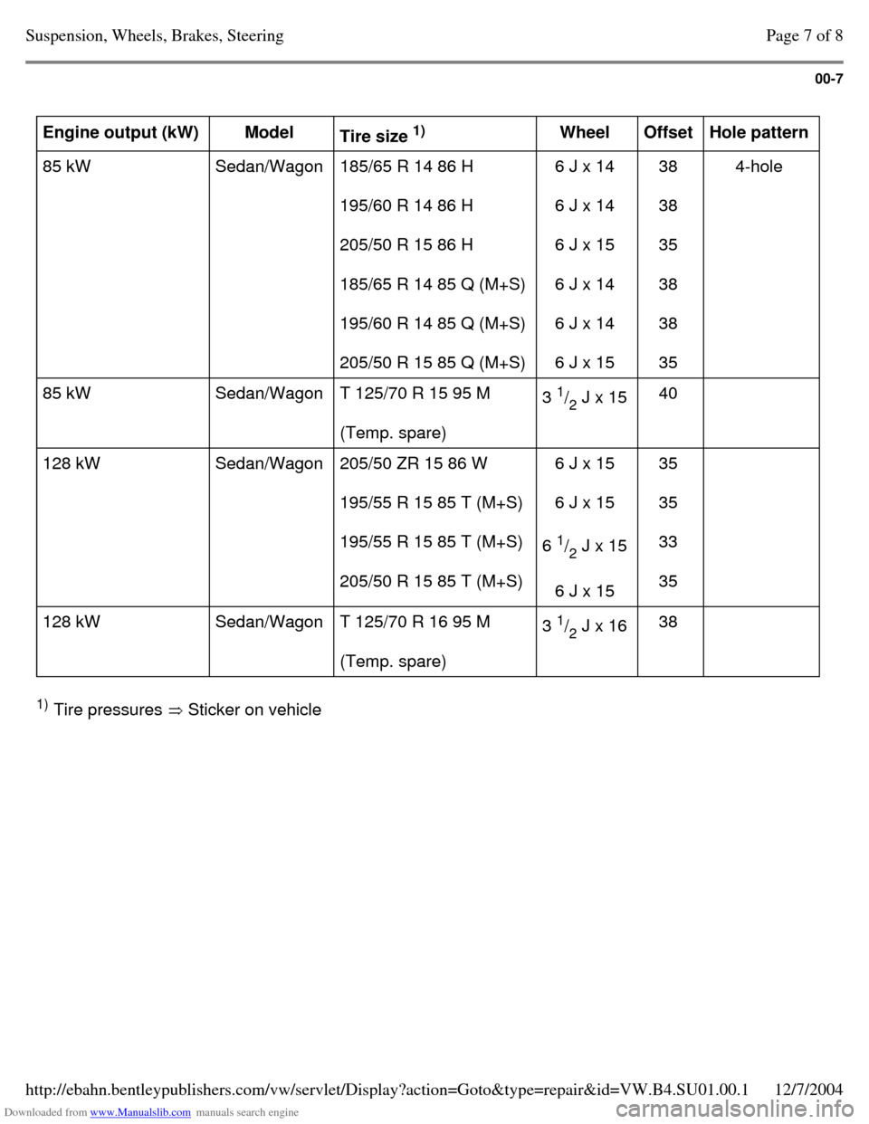
Engine output (kW)
Model
Tire size 1)
Wheel
Offset
Hole pattern
85 kW Sedan/Wagon 185/65 R 14 86 H
195/60 R 14 86 H
205/50 R 15 86 H
185/65 R 14 85 Q (M+S)
195/60 R 14 85 Q (M+S)
205/50 R 15 85 Q (M+S) 6 J x 14
6 J x 14
6 J x 15
6 J x 14
6 J x 14
6 J x 15 38
38
35
38
38
35 4-hole
85 kW Sedan/Wagon T 125/70 R 15 95 M
(Temp. spare) 3 1
/
2 J x 15
40
128 kW Sedan/Wagon 205/50 ZR 15 86 W
195/55 R 15 85 T (M+S)
195/55 R 15 85 T (M+S)
205/50 R 15 85 T (M+S) 6 J x 15
6 J x 15
6 1
/
2 J x 15
6 J x 15 35
35
33
35
128 kW Sedan/Wagon T 125/70 R 16 95 M
(Temp. spare) 3 1
/
2 J x 16
38 1)
Tire pressures Sticker on vehicle Page 7 of 8Suspension, Wheels, Brakes, Steering12/7/2004http://ebahn.bentleypublishers.com/vw/servlet/Display?action=Goto&type=repair&id=VW.B4.SU01.00.1
Page 14 of 369
Downloaded from www.Manualslib.com manuals search engine 00-8
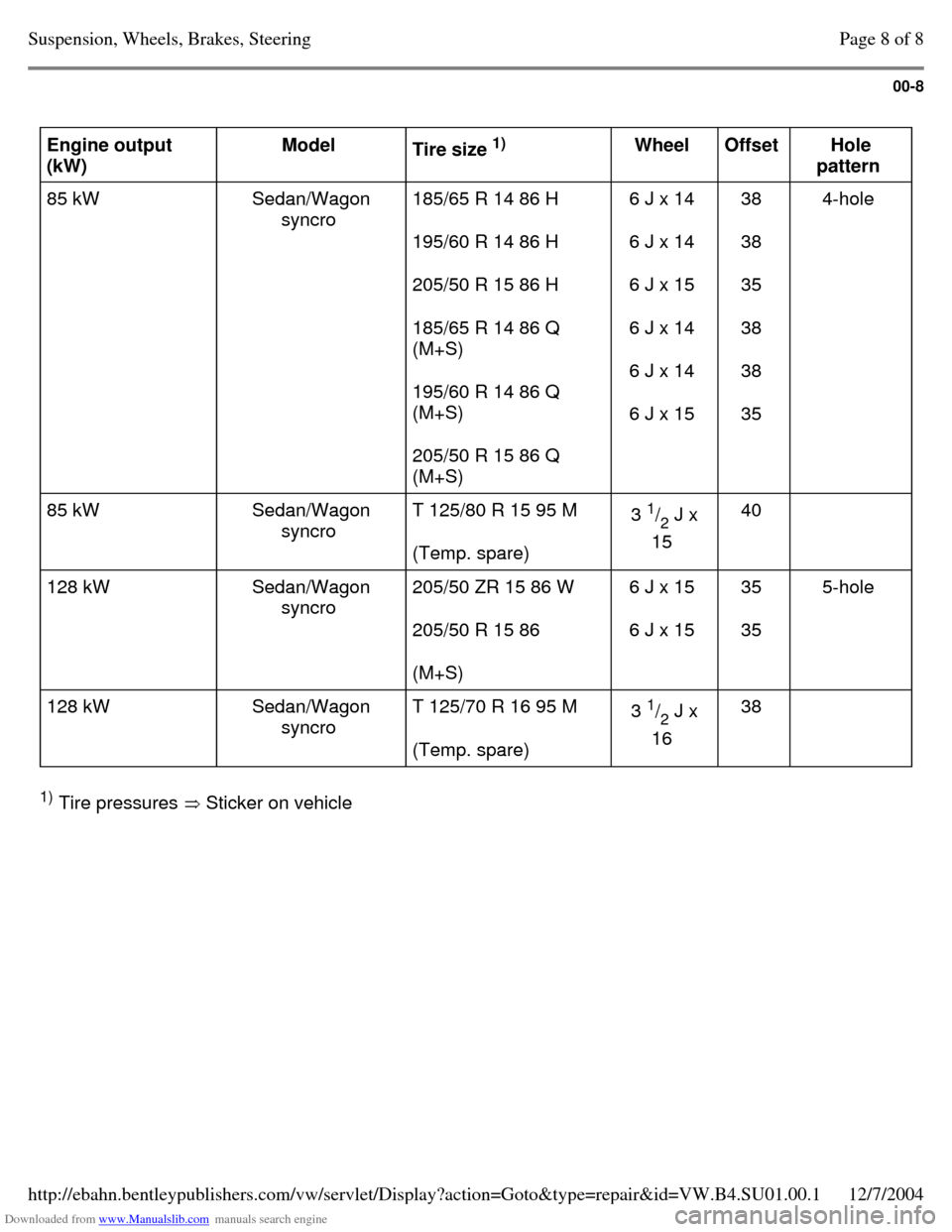
Engine output
(kW) Model
Tire size 1)
Wheel
Offset
Hole
pattern
85 kW Sedan/Wagon
syncro 185/65 R 14 86 H
195/60 R 14 86 H
205/50 R 15 86 H
185/65 R 14 86 Q
(M+S)
195/60 R 14 86 Q
(M+S)
205/50 R 15 86 Q
(M+S) 6 J x 14
6 J x 14
6 J x 15
6 J x 14
6 J x 14
6 J x 15 38
38
35
38
38
35 4-hole
85 kW Sedan/Wagon
syncro T 125/80 R 15 95 M
(Temp. spare) 3 1
/
2 J x
15 40
128 kW Sedan/Wagon
syncro 205/50 ZR 15 86 W
205/50 R 15 86
(M+S) 6 J x 15
6 J x 15 35
35 5-hole
128 kW Sedan/Wagon
syncro T 125/70 R 16 95 M
(Temp. spare) 3 1
/
2 J x
16 38 1)
Tire pressures Sticker on vehicle Page 8 of 8Suspension, Wheels, Brakes, Steering12/7/2004http://ebahn.bentleypublishers.com/vw/servlet/Display?action=Goto&type=repair&id=VW.B4.SU01.00.1
Page 15 of 369
Downloaded from www.Manualslib.com manuals search engine 40-1
Front Wheel
Suspension, Shafts
and Axle
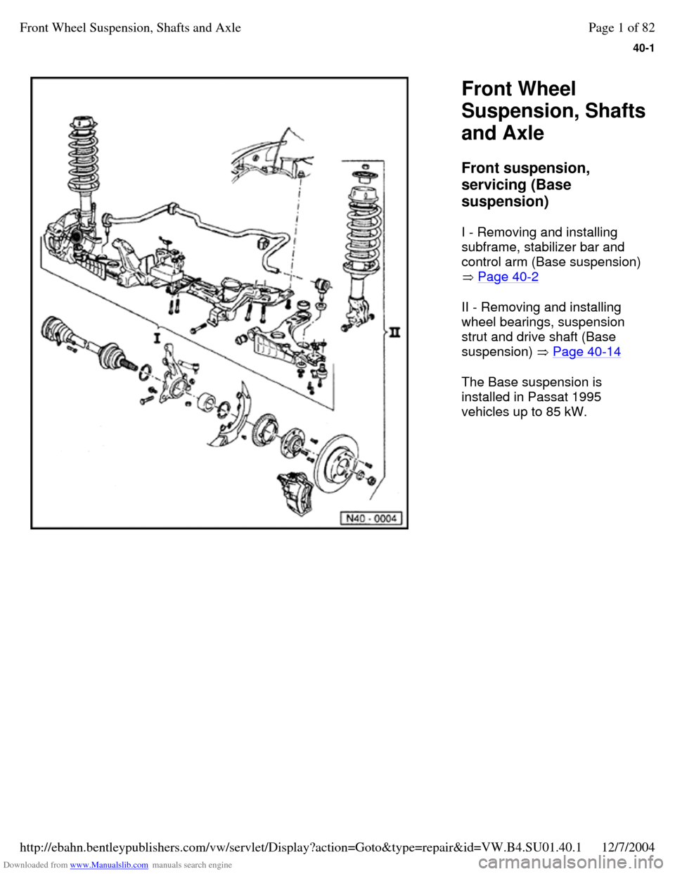
Front suspension,
servicing (Base
suspension)
I - Removing and installing
subframe, stabilizer bar and
control arm (Base suspension)
Page 40-2
II - Removing and installing
wheel bearings, suspension
strut and drive shaft (Base
suspension) Page 40-14
The Base suspension is
installed in Passat 1995
vehicles up to 85 kW. Page 1 of 82Front Wheel Suspension, Shafts and Axle12/7/2004http://ebahn.bentleypublishers.com/vw/servlet/Display?action=Goto&type=repair&id=VW.B4.SU01.40.1
Page 16 of 369
Downloaded from www.Manualslib.com manuals search engine 40-2
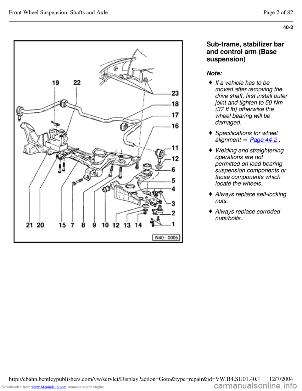
Sub-frame, stabilizer bar
and control arm (Base
suspension)
Note: If a vehicle has to be
moved after removing the
drive shaft, first install outer joint and tighten to 50 Nm (37 ft lb) otherwise the
wheel bearing will be
damaged. Specifications for wheel
alignment Page 44-2 . Welding and straightening
operations are not
permitted on load bearing
suspension components or
those components which
locate the wheels. Always replace self-locking
nuts. Always replace corroded
nuts/bolts. Page 2 of 82Front Wheel Suspension, Shafts and Axle12/7/2004http://ebahn.bentleypublishers.com/vw/servlet/Display?action=Goto&type=repair&id=VW.B4.SU01.40.1
Page 17 of 369
Downloaded from www.Manualslib.com manuals search engine 40-3
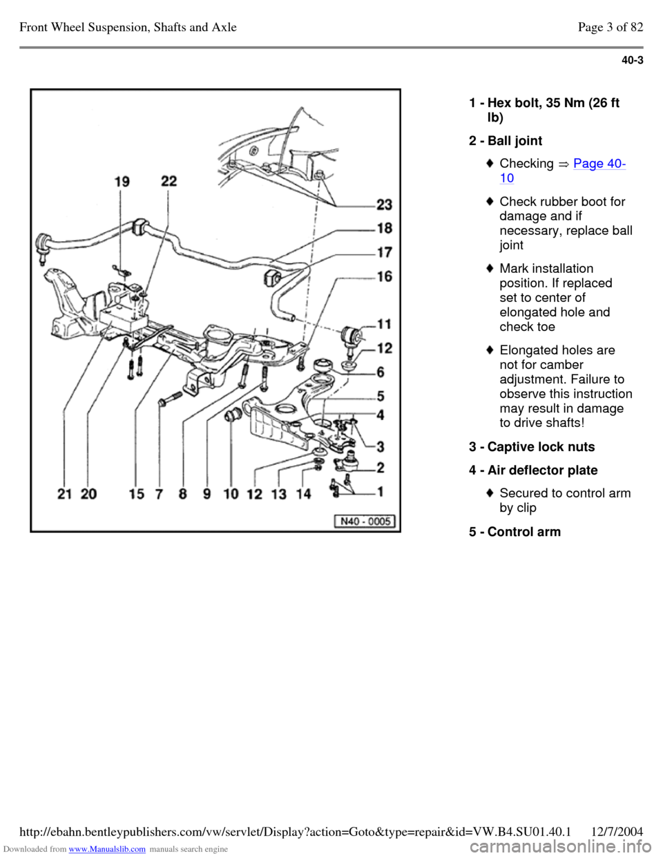
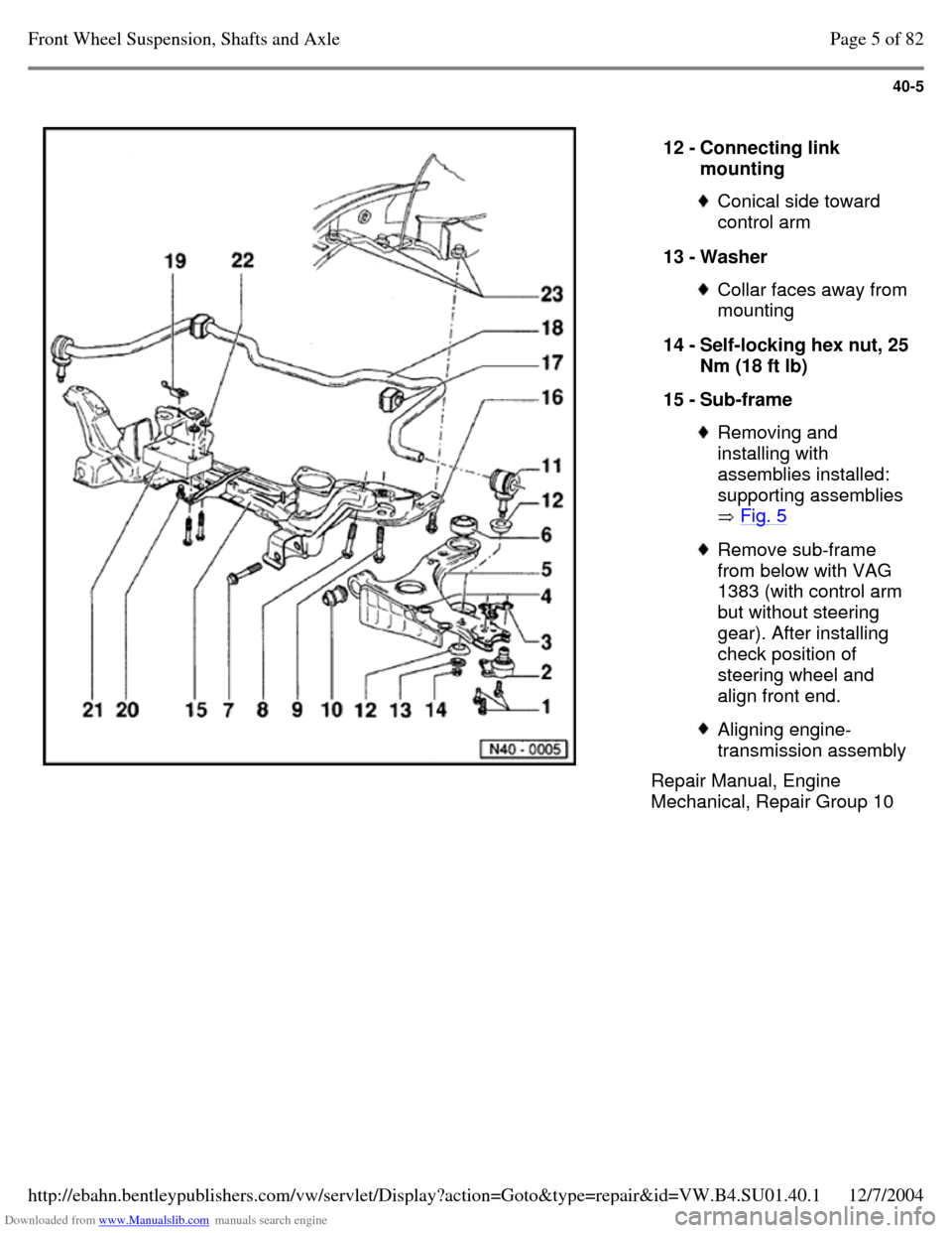
1 - Hex bolt, 35 Nm (26 ft
lb)
2 - Ball joint Checking Page 40-10 Check rubber boot for
damage and if necessary, replace ball joint Mark installation
position. If replaced
set to center of
elongated hole and
check toe Elongated holes are
not for camber
adjustment. Failure to observe this instruction may result in damage
to drive shafts!
3 - Captive lock nuts
4 - Air deflector plate Secured to control arm by clip
5 - Control arm Page 3 of 82Front Wheel Suspension, Shafts and Axle12/7/2004http://ebahn.bentleypublishers.com/vw/servlet/Display?action=Goto&type=repair&id=VW.B4.SU01.40.1
Page 18 of 369
Downloaded from www.Manualslib.com manuals search engine 40-4
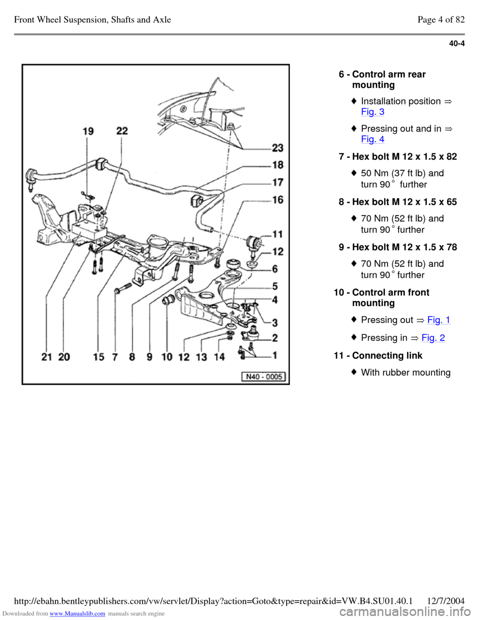
6 - Control arm rear
mounting Installation position
Fig. 3 Pressing out and in
Fig. 4 7 - Hex bolt M 12 x 1.5 x 82 50 Nm (37 ft lb) and
turn 90 further 8 - Hex bolt M 12 x 1.5 x 65 70 Nm (52 ft lb) and
turn 90further 9 - Hex bolt M 12 x 1.5 x 78 70 Nm (52 ft lb) and
turn 90further 10 - Control arm front
mounting Pressing out Fig. 1 Pressing in Fig. 2 11 - Connecting link With rubber mounting Page 4 of 82Front Wheel Suspension, Shafts and Axle12/7/2004http://ebahn.bentleypublishers.com/vw/servlet/Display?action=Goto&type=repair&id=VW.B4.SU01.40.1
Page 19 of 369
Downloaded from www.Manualslib.com manuals search engine 40-5
Repair Manual, Engine
Mechanical, Repair Group 10 12 - Connecting link
mounting Conical side toward
control arm
13 - Washer Collar faces away from mounting
14 - Self-locking hex nut, 25 Nm (18 ft lb)
15 - Sub-frame Removing and
installing with
assemblies installed:
supporting assemblies
Fig. 5 Remove sub-frame
from below with VAG
1383 (with control arm
but without steering
gear). After installing
check position of
steering wheel and
align front end. Aligning engine-
transmission assembly Page 5 of 82Front Wheel Suspension, Shafts and Axle12/7/2004http://ebahn.bentleypublishers.com/vw/servlet/Display?action=Goto&type=repair&id=VW.B4.SU01.40.1
Page 20 of 369
Downloaded from www.Manualslib.com manuals search engine 40-6
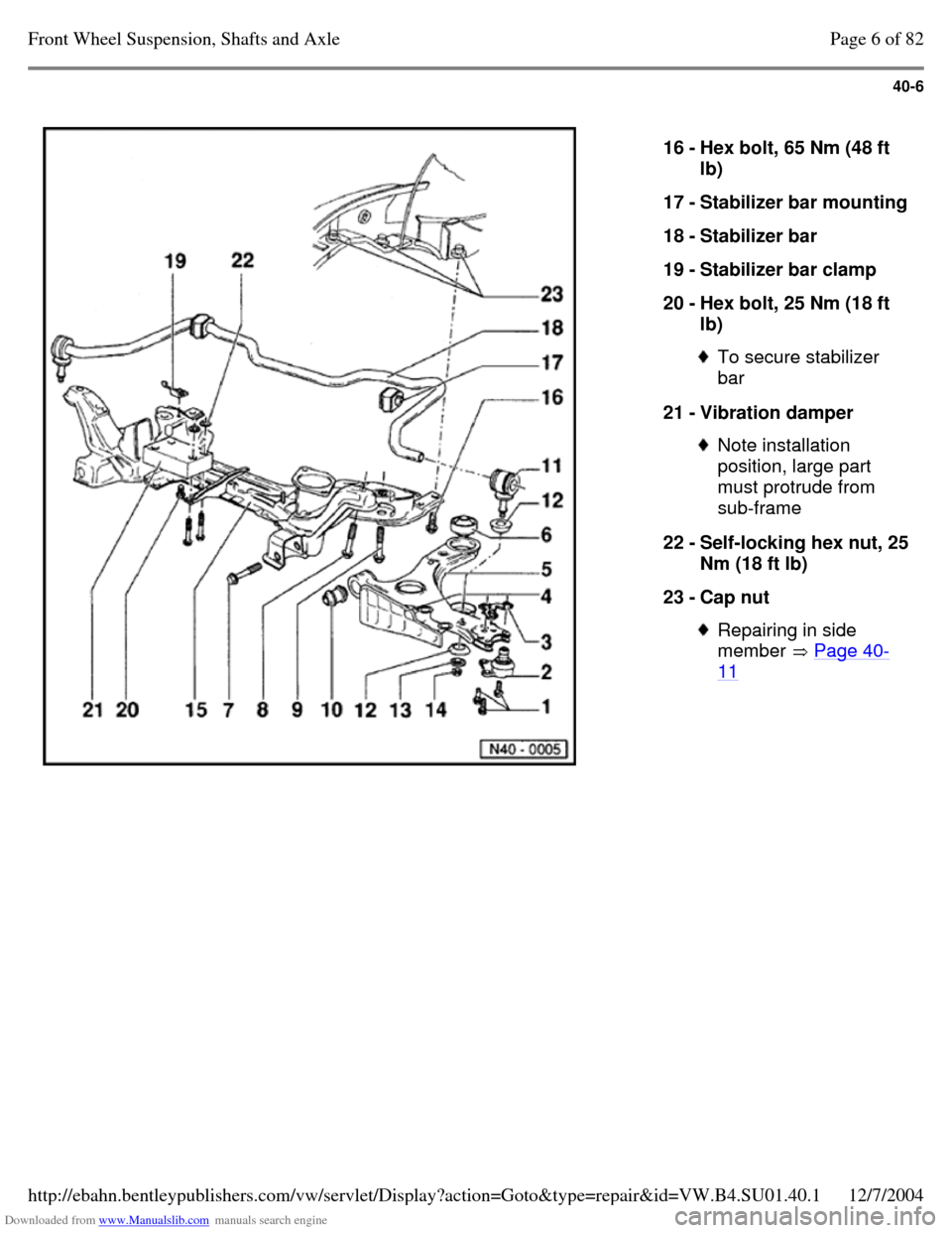
16 - Hex bolt, 65 Nm (48 ft
lb)
17 - Stabilizer bar mounting 18 - Stabilizer bar
19 - Stabilizer bar clamp
20 - Hex bolt, 25 Nm (18 ft
lb) To secure stabilizer
bar
21 - Vibration damper Note installation
position, large part
must protrude from
sub-frame
22 - Self-locking hex nut, 25 Nm (18 ft lb)
23 - Cap nut Repairing in side
member Page 40-11 Page 6 of 82Front Wheel Suspension, Shafts and Axle12/7/2004http://ebahn.bentleypublishers.com/vw/servlet/Display?action=Goto&type=repair&id=VW.B4.SU01.40.1