VOLKSWAGEN PASSAT 1997 B3, B4 / 3.G Service Service Manual
PASSAT 1997 B3, B4 / 3.G
VOLKSWAGEN
VOLKSWAGEN
https://www.carmanualsonline.info/img/18/7419/w960_7419-0.png
VOLKSWAGEN PASSAT 1997 B3, B4 / 3.G Service Service Manual
Trending: differential, traction control, wheel, load capacity, tow bar, key, steering wheel adjustment
Page 41 of 369
Downloaded from www.Manualslib.com manuals search engine 40-27
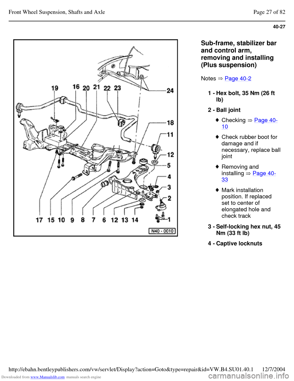
Sub-frame, stabilizer bar
and control arm,
removing and installing
(Plus suspension)
Notes Page 40-2 1 - Hex bolt, 35 Nm (26 ft
lb)
2 - Ball joint Checking Page 40-10 Check rubber boot for
damage and if necessary, replace ball joint Removing and
installing Page 40-33 Mark installation
position. If replaced
set to center of
elongated hole and
check track
3 - Self-locking hex nut, 45 Nm (33 ft lb)
4 - Captive locknuts Page 27 of 82Front Wheel Suspension, Shafts and Axle12/7/2004http://ebahn.bentleypublishers.com/vw/servlet/Display?action=Goto&type=repair&id=VW.B4.SU01.40.1
Page 42 of 369
Downloaded from www.Manualslib.com manuals search engine 40-28
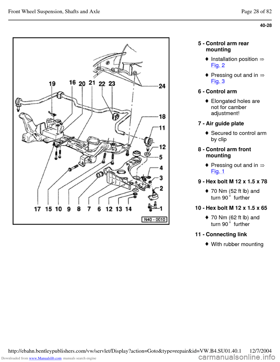
5 - Control arm rear
mounting Installation position
Fig. 2 Pressing out and in
Fig. 3 6 - Control arm Elongated holes are
not for camber
adjustment!
7 - Air guide plate Secured to control arm by clip
8 - Control arm front
mounting Pressing out and in
Fig. 1 9 - Hex bolt M 12 x 1.5 x 78 70 Nm (52 ft lb) and
turn 90 further 10 - Hex bolt M 12 x 1.5 x 65 70 Nm (62 ft lb) and
turn 90 further 11 - Connecting link With rubber mounting Page 28 of 82Front Wheel Suspension, Shafts and Axle12/7/2004http://ebahn.bentleypublishers.com/vw/servlet/Display?action=Goto&type=repair&id=VW.B4.SU01.40.1
Page 43 of 369
Downloaded from www.Manualslib.com manuals search engine 40-29
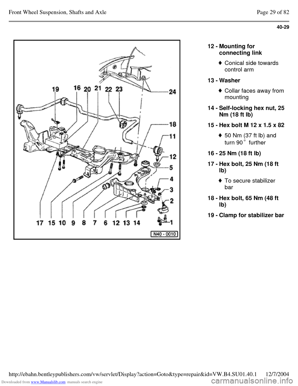
12 - Mounting for
connecting link Conical side towards
control arm
13 - Washer Collar faces away from mounting
14 - Self-locking hex nut, 25 Nm (18 ft lb)
15 - Hex bolt M 12 x 1.5 x 82 50 Nm (37 ft lb) and
turn 90 further 16 - 25 Nm (18 ft lb)
17 - Hex bolt, 25 Nm (18 ft
lb) To secure stabilizer
bar
18 - Hex bolt, 65 Nm (48 ft
lb)
19 - Clamp for stabilizer bar Page 29 of 82Front Wheel Suspension, Shafts and Axle12/7/2004http://ebahn.bentleypublishers.com/vw/servlet/Display?action=Goto&type=repair&id=VW.B4.SU01.40.1
Page 44 of 369
Downloaded from www.Manualslib.com manuals search engine 40-30
Repair Manual, Engine
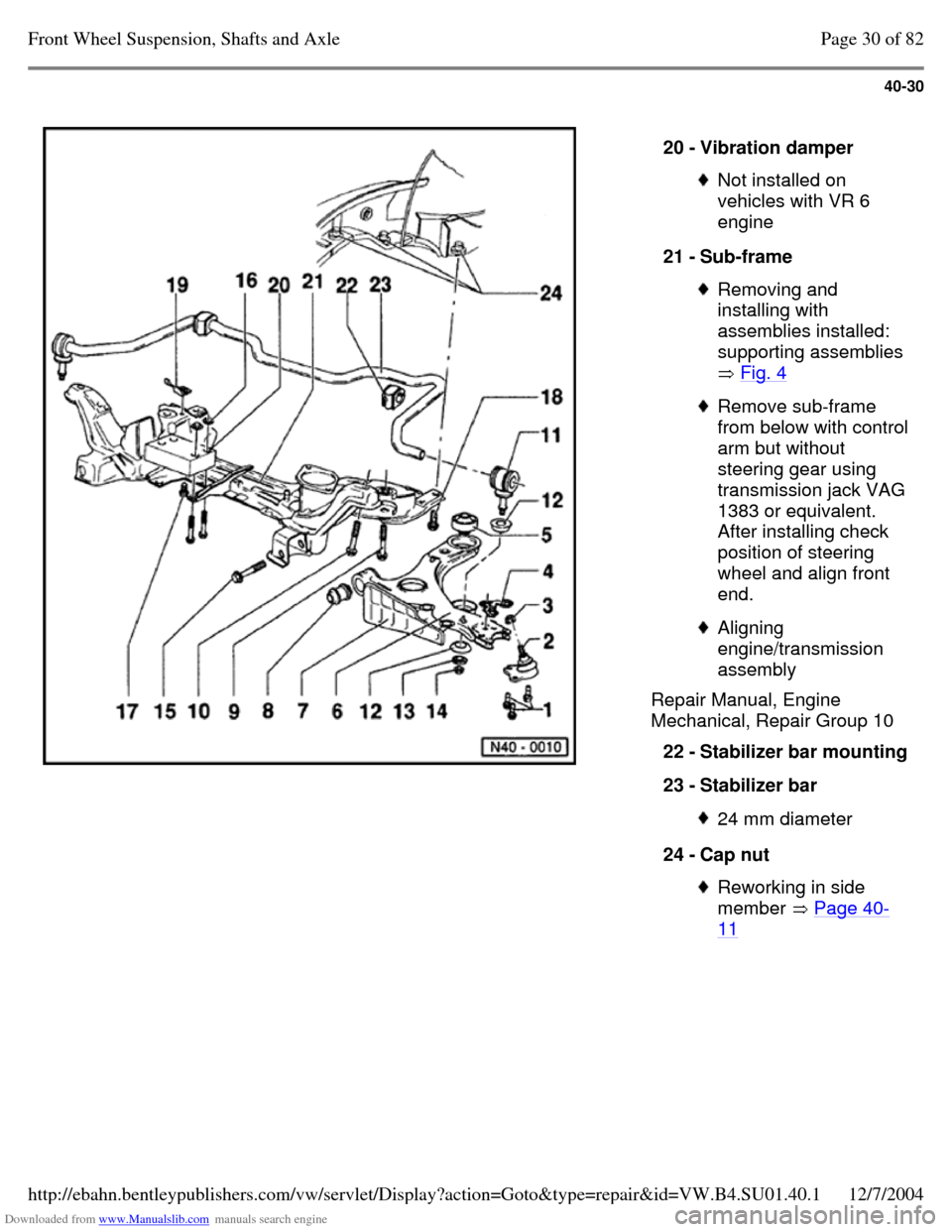
Mechanical, Repair Group 10 20 - Vibration damper Not installed on
vehicles with VR 6
engine
21 - Sub-frame Removing and
installing with
assemblies installed:
supporting assemblies
Fig. 4 Remove sub-frame from below with control arm but without
steering gear using transmission jack VAG 1383 or equivalent.
After installing check
position of steering
wheel and align front
end. Aligning
engine/transmission
assembly
22 - Stabilizer bar mounting 23 - Stabilizer bar 24 mm diameter 24 - Cap nut Reworking in side
member Page 40-11 Page 30 of 82Front Wheel Suspension, Shafts and Axle12/7/2004http://ebahn.bentleypublishers.com/vw/servlet/Display?action=Goto&type=repair&id=VW.B4.SU01.40.1
Page 45 of 369
Downloaded from www.Manualslib.com manuals search engine 40-31
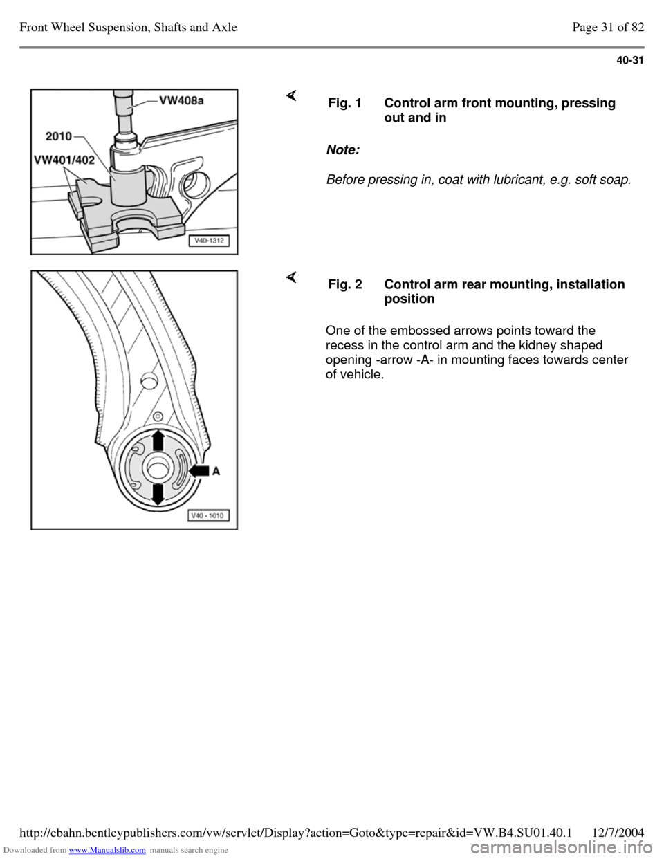
Note:
Before pressing in, coat with lubricant, e.g. soft soap. Fig. 1 Control arm front mounting, pressing
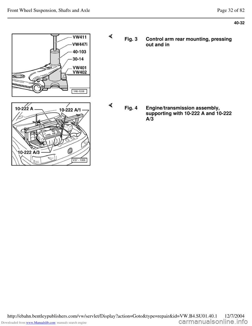
out and in One of the embossed arrows points toward the
recess in the control arm and the kidney shaped
opening -arrow -A- in mounting faces towards center
of vehicle. Fig. 2 Control arm rear mounting, installation
position Page 31 of 82Front Wheel Suspension, Shafts and Axle12/7/2004http://ebahn.bentleypublishers.com/vw/servlet/Display?action=Goto&type=repair&id=VW.B4.SU01.40.1
Page 46 of 369
Downloaded from www.Manualslib.com manuals search engine 40-32
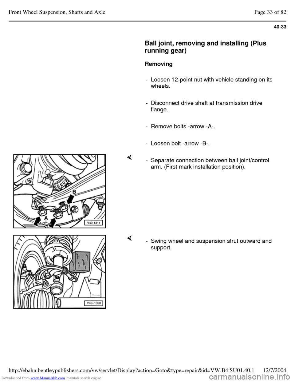
Fig. 3 Control arm rear mounting, pressing
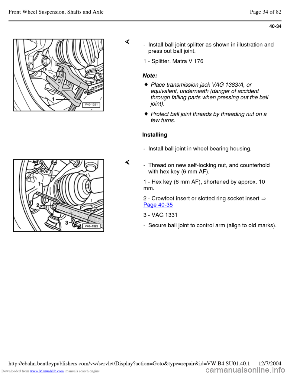
out and in Fig. 4 Engine/transmission assembly,
supporting with 10-222 A and 10-222
A/3 Page 32 of 82Front Wheel Suspension, Shafts and Axle12/7/2004http://ebahn.bentleypublishers.com/vw/servlet/Display?action=Goto&type=repair&id=VW.B4.SU01.40.1
Page 47 of 369
Downloaded from www.Manualslib.com manuals search engine 40-33
Ball joint, removing and installing (Plus
running gear)
Removing
- Loosen 12-point nut with vehicle standing on its
wheels.
- Disconnect drive shaft at transmission drive
flange.
- Remove bolts -arrow -A-.
- Loosen bolt -arrow -B-. - Separate connection between ball joint/control
arm. (First mark installation position). - Swing wheel and suspension strut outward and
support. Page 33 of 82Front Wheel Suspension, Shafts and Axle12/7/2004http://ebahn.bentleypublishers.com/vw/servlet/Display?action=Goto&type=repair&id=VW.B4.SU01.40.1
Page 48 of 369
Downloaded from www.Manualslib.com manuals search engine 40-34
Note:
Installing - Install ball joint splitter as shown in illustration and
press out ball joint.
1 - Splitter. Matra V 176 Place transmission jack VAG 1383/A, or
equivalent, underneath (danger of accident
through falling parts when pressing out the ball joint). Protect ball joint threads by threading nut on a
few turns.
- Install ball joint in wheel bearing housing. - Thread on new self-locking nut, and counterhold
with hex key (6 mm AF).
1 - Hex key (6 mm AF), shortened by approx. 10
mm.
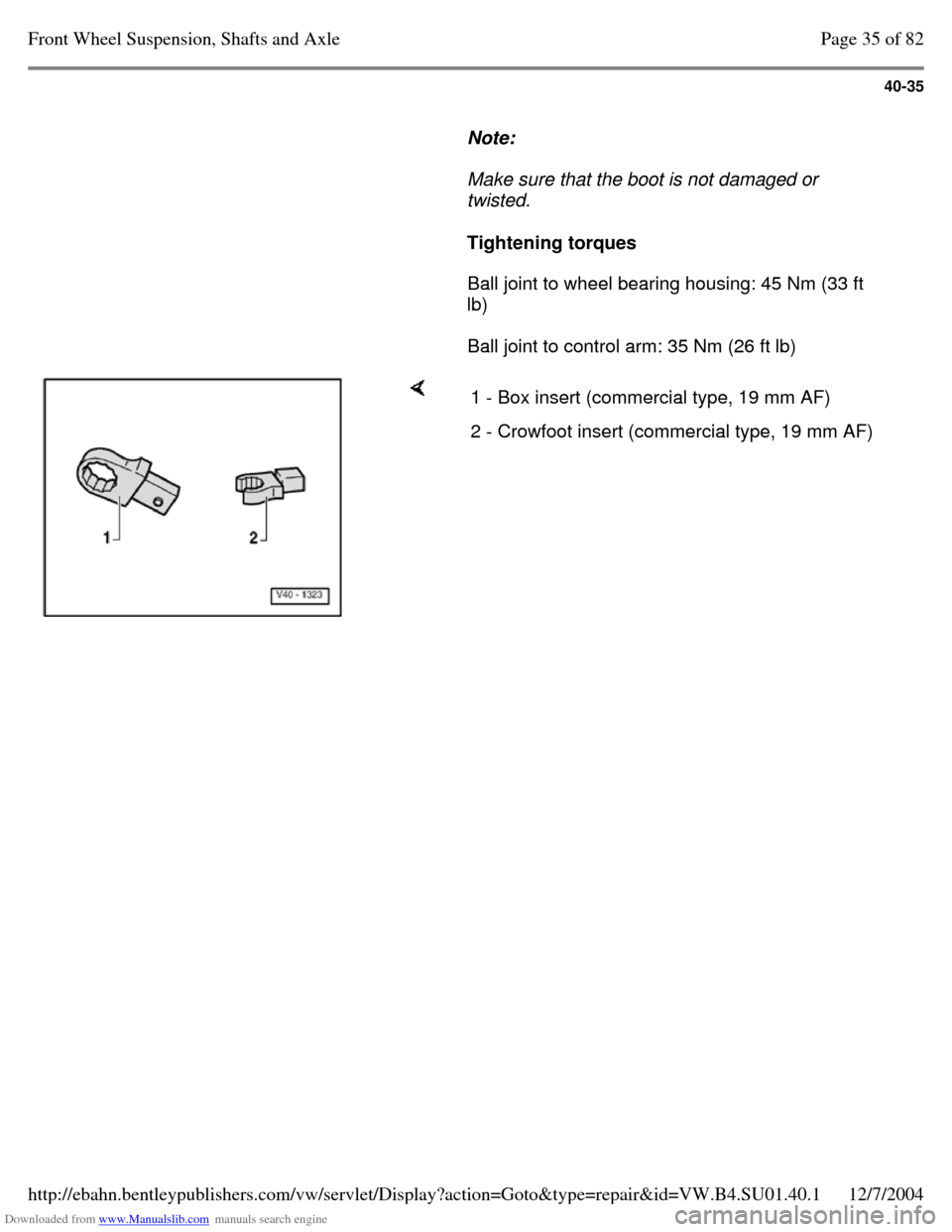
2 - Crowfoot insert or slotted ring socket insert
Page 40-35 3 - VAG 1331 - Secure ball joint to control arm (align to old marks). Page 34 of 82Front Wheel Suspension, Shafts and Axle12/7/2004http://ebahn.bentleypublishers.com/vw/servlet/Display?action=Goto&type=repair&id=VW.B4.SU01.40.1
Page 49 of 369
Downloaded from www.Manualslib.com manuals search engine 40-35
Note:
Make sure that the boot is not damaged or
twisted.
Tightening torques
Ball joint to wheel bearing housing: 45 Nm (33 ft
lb)
Ball joint to control arm: 35 Nm (26 ft lb) 1 - Box insert (commercial type, 19 mm AF) 2 - Crowfoot insert (commercial type, 19 mm AF) Page 35 of 82Front Wheel Suspension, Shafts and Axle12/7/2004http://ebahn.bentleypublishers.com/vw/servlet/Display?action=Goto&type=repair&id=VW.B4.SU01.40.1
Page 50 of 369
Downloaded from www.Manualslib.com manuals search engine 40-36
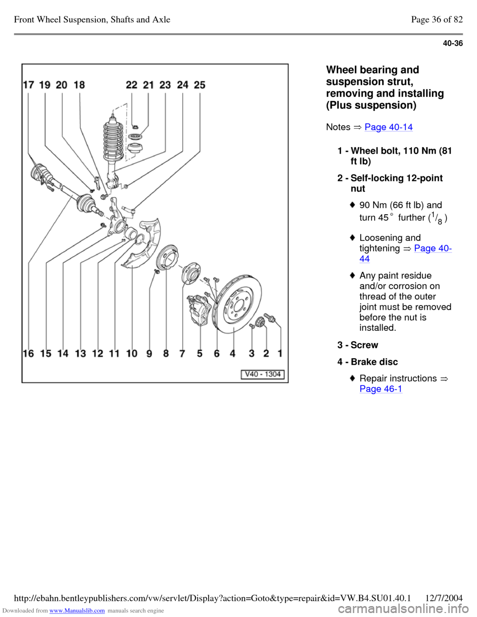
Wheel bearing and
suspension strut,
removing and installing
(Plus suspension)
Notes Page 40-14 1 - Wheel bolt, 110 Nm (81
ft lb)
2 - Self-locking 12-point
nut 90 Nm (66 ft lb) and
turn 45 further (1
/
8 ) Loosening and
tightening Page 40-44 Any paint residue
and/or corrosion on
thread of the outer
joint must be removed
before the nut is
installed.
3 - Screw
4 - Brake disc Repair instructions
Page 46-1 Page 36 of 82Front Wheel Suspension, Shafts and Axle12/7/2004http://ebahn.bentleypublishers.com/vw/servlet/Display?action=Goto&type=repair&id=VW.B4.SU01.40.1
Trending: boot, steering wheel adjustment, engine coolant, seats, automatic transmission, sensor, wheel alignment
