Abs engine VOLKSWAGEN PASSAT 1997 B3, B4 / 3.G Service User Guide
[x] Cancel search | Manufacturer: VOLKSWAGEN, Model Year: 1997, Model line: PASSAT, Model: VOLKSWAGEN PASSAT 1997 B3, B4 / 3.GPages: 369, PDF Size: 12.33 MB
Page 112 of 369
Downloaded from www.Manualslib.com manuals search engine 42-16
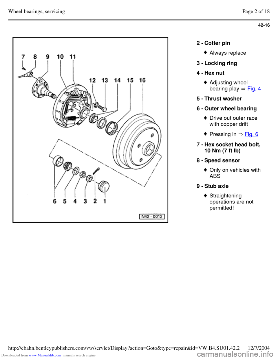
2 - Cotter pin Always replace 3 - Locking ring
4 - Hex nut Adjusting wheel
bearing play Fig. 4 5 - Thrust washer
6 - Outer wheel bearing Drive out outer race
with copper drift Pressing in Fig. 6 7 - Hex socket head bolt,
10 Nm (7 ft lb)
8 - Speed sensor Only on vehicles with
ABS
9 - Stub axle Straightening
operations are not
permitted! Page 2 of 18Wheel bearings, servicing12/7/2004http://ebahn.bentleypublishers.com/vw/servlet/Display?action=Goto&type=repair&id=VW.B4.SU01.42.2
Page 120 of 369
Downloaded from www.Manualslib.com manuals search engine 42-24
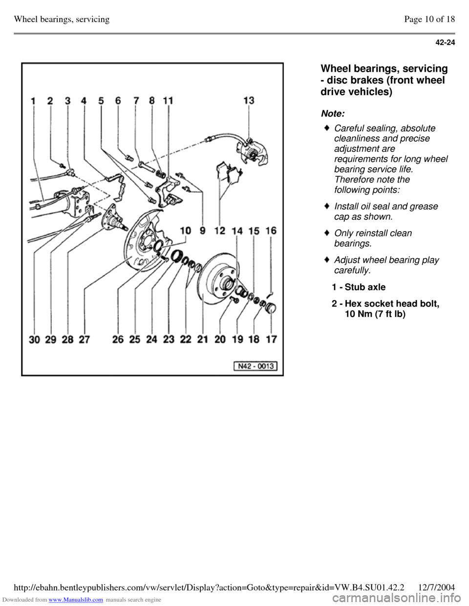
Wheel bearings, servicing
- disc brakes (front wheel
drive vehicles)
Note: Careful sealing, absolute
cleanliness and precise
adjustment are requirements for long wheel bearing service life.
Therefore note the
following points: Install oil seal and grease
cap as shown. Only reinstall clean
bearings. Adjust wheel bearing play
carefully.
1 - Stub axle
2 - Hex socket head bolt,
10 Nm (7 ft lb) Page 10 of 18Wheel bearings, servicing12/7/2004http://ebahn.bentleypublishers.com/vw/servlet/Display?action=Goto&type=repair&id=VW.B4.SU01.42.2
Page 121 of 369
Downloaded from www.Manualslib.com manuals search engine 42-25
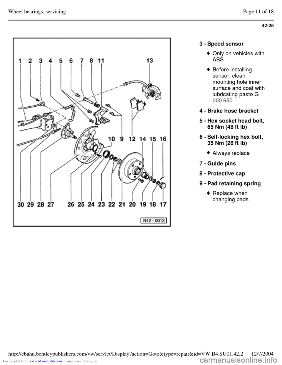
3 - Speed sensor Only on vehicles with
ABS Before installing
sensor, clean
mounting hole inner
surface and coat with
lubricating paste G
000 650
4 - Brake hose bracket
5 - Hex socket head bolt,
65 Nm (48 ft lb)
6 - Self-locking hex bolt,
35 Nm (26 ft lb) Always replace 7 - Guide pins
8 - Protective cap
9 - Pad retaining spring Replace when
changing pads Page 11 of 18Wheel bearings, servicing12/7/2004http://ebahn.bentleypublishers.com/vw/servlet/Display?action=Goto&type=repair&id=VW.B4.SU01.42.2
Page 123 of 369
Downloaded from www.Manualslib.com manuals search engine 42-27
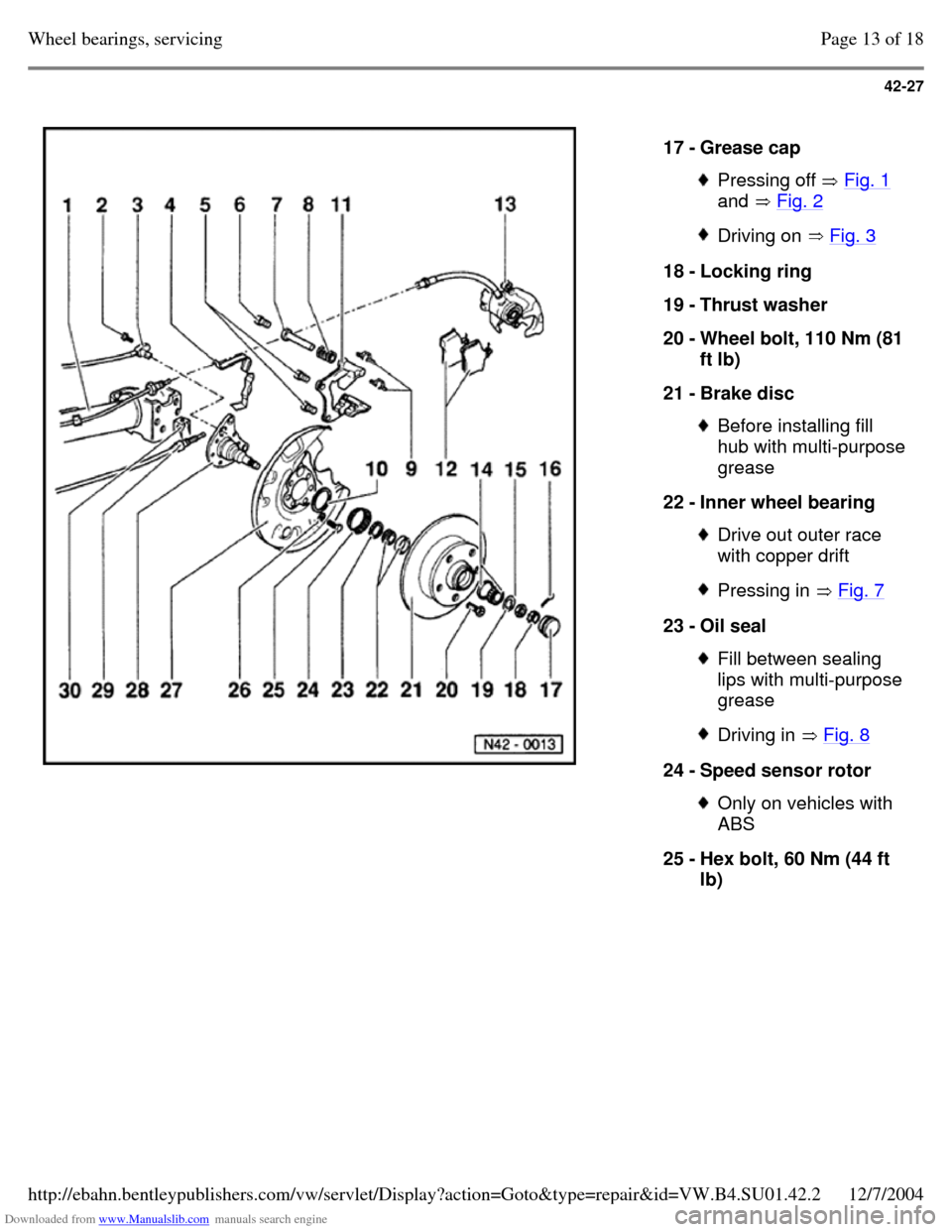
17 - Grease cap Pressing off Fig. 1
and Fig. 2 Driving on Fig. 3 18 - Locking ring
19 - Thrust washer
20 - Wheel bolt, 110 Nm (81
ft lb)
21 - Brake disc Before installing fill
hub with multi-purpose grease
22 - Inner wheel bearing Drive out outer race
with copper drift Pressing in Fig. 7 23 - Oil seal Fill between sealing
lips with multi-purpose
grease Driving in Fig. 8 24 - Speed sensor rotor Only on vehicles with
ABS
25 - Hex bolt, 60 Nm (44 ft
lb) Page 13 of 18Wheel bearings, servicing12/7/2004http://ebahn.bentleypublishers.com/vw/servlet/Display?action=Goto&type=repair&id=VW.B4.SU01.42.2
Page 129 of 369
Downloaded from www.Manualslib.com manuals search engine 42-33
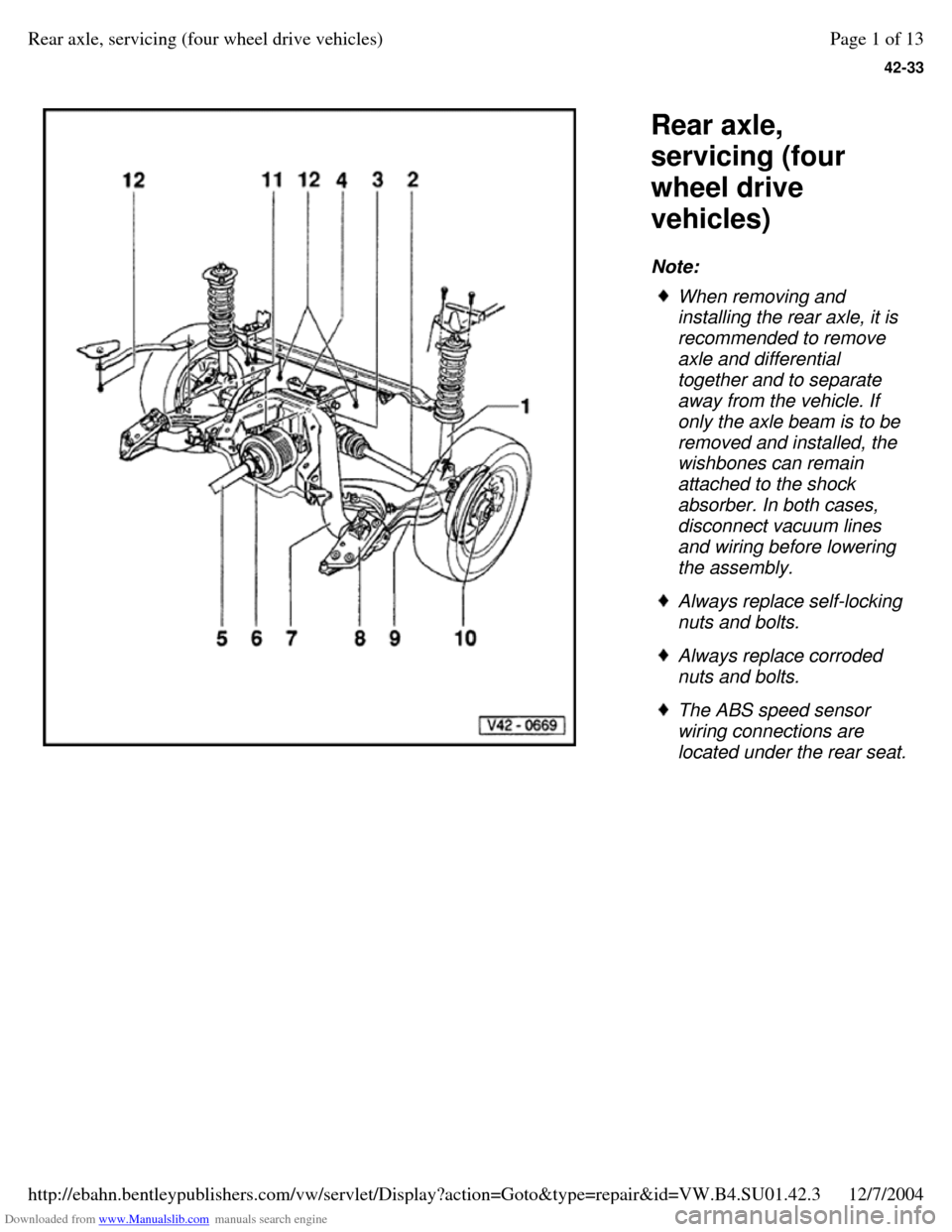
Rear axle,
servicing (four
wheel drive
vehicles)
Note: When removing and
installing the rear axle, it is
recommended to remove
axle and differential
together and to separate
away from the vehicle. If
only the axle beam is to be
removed and installed, the
wishbones can remain
attached to the shock
absorber. In both cases,
disconnect vacuum lines
and wiring before lowering
the assembly. Always replace self-locking
nuts and bolts. Always replace corroded
nuts and bolts. The ABS speed sensor
wiring connections are
located under the rear seat. Page 1 of 13Rear axle, servicing (four wheel drive vehicles)12/7/2004http://ebahn.bentleypublishers.com/vw/servlet/Display?action=Goto&type=repair&id=VW.B4.SU01.42.3
Page 151 of 369
Downloaded from www.Manualslib.com manuals search engine 42-55
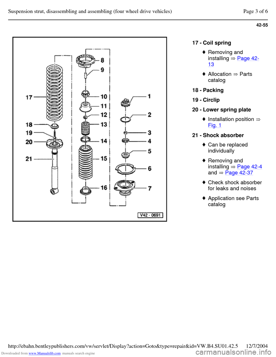
17 - Coil spring Removing and
installing Page 42-13 Allocation Parts
catalog 18 - Packing
19 - Circlip
20 - Lower spring plate Installation position
Fig. 1 21 - Shock absorber Can be replaced
individually Removing and
installing Page 42-4
and Page 42-37 Check shock absorber
for leaks and noises Application see Parts
catalog Page 3 of 6Suspension strut, disassembling and assembling (four wheel drive vehicles)12/7/2004http://ebahn.bentleypublishers.com/vw/servlet/Display?action=Goto&type=repair&id=VW.B4.SU01.42.5
Page 152 of 369
Downloaded from www.Manualslib.com manuals search engine 42-56
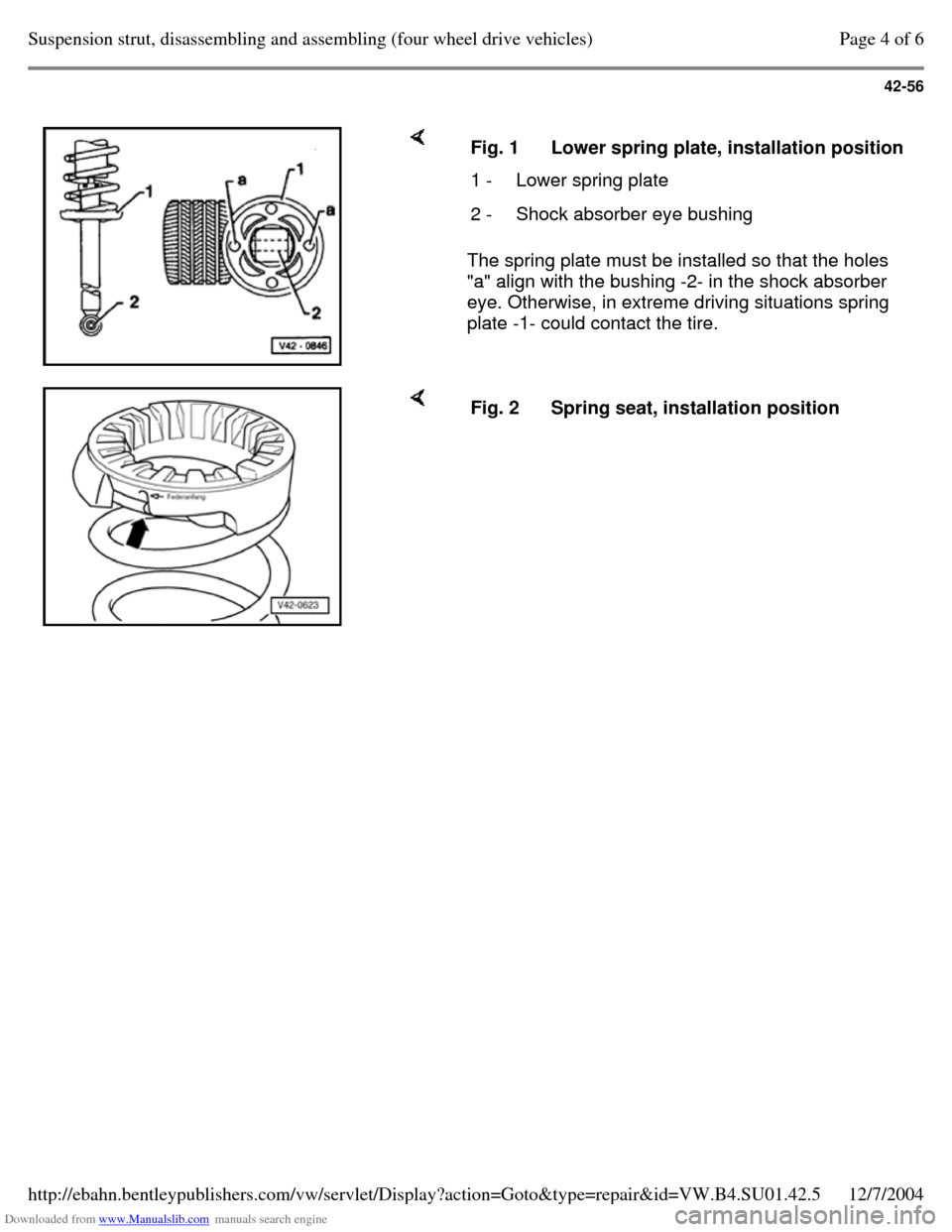
The spring plate must be installed so that the holes
"a" align with the bushing -2- in the shock absorber
eye. Otherwise, in extreme driving situations spring
plate -1- could contact the tire. Fig. 1 Lower spring plate, installation position 1 - Lower spring plate 2 - Shock absorber eye bushing Fig. 2 Spring seat, installation position Page 4 of 6Suspension strut, disassembling and assembling (four wheel drive vehicles)12/7/2004http://ebahn.bentleypublishers.com/vw/servlet/Display?action=Goto&type=repair&id=VW.B4.SU01.42.5
Page 153 of 369
Downloaded from www.Manualslib.com manuals search engine 42-57
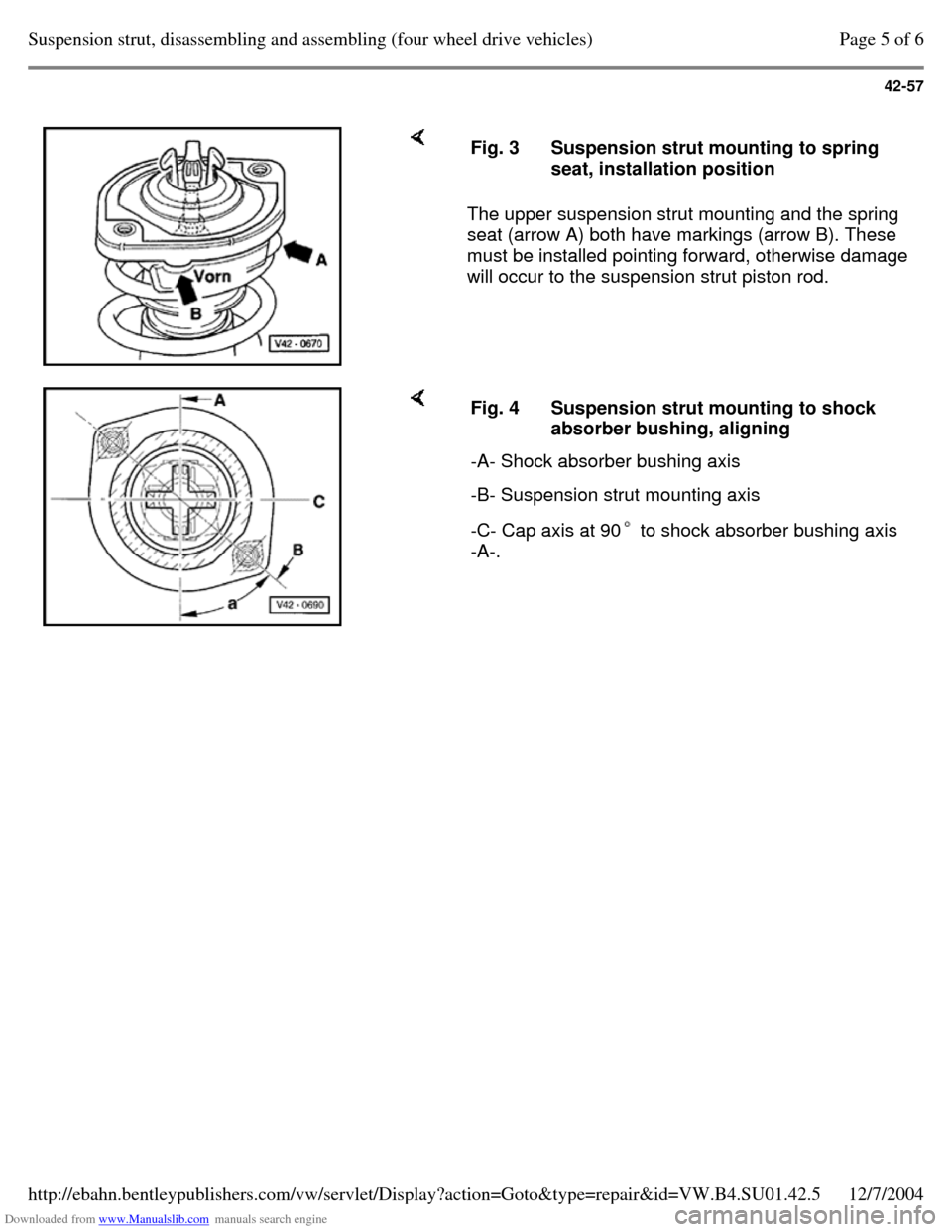
The upper suspension strut mounting and the spring
seat (arrow A) both have markings (arrow B). These
must be installed pointing forward, otherwise damage
will occur to the suspension strut piston rod. Fig. 3 Suspension strut mounting to spring
seat, installation position Fig. 4 Suspension strut mounting to shock
absorber bushing, aligning
-A- Shock absorber bushing axis -B- Suspension strut mounting axis -C- Cap axis at 90 to shock absorber bushing axis
-A-. Page 5 of 6Suspension strut, disassembling and assembling (four wheel drive vehicles)12/7/2004http://ebahn.bentleypublishers.com/vw/servlet/Display?action=Goto&type=repair&id=VW.B4.SU01.42.5
Page 170 of 369
Downloaded from www.Manualslib.com manuals search engine 45-1
Anti-locking Brake System
(ABS) and Anti-locking Brake
System with Electronic
Differential Lock (ABS/EDL)
Teves 04
The ABS, ABS/EDL brake system is divided
diagonally. The servo-assist is effected
pneumatically, by the vacuum brake servo unit.
Located between the brake master cylinder and
the vacuum servo unit is a mounting bracket for
the hydraulic unit with pump.
The hydraulic unit together with pump, supplies
only the anti-locking brake system (ABS) or anti-
locking brake system and traction control system
(ABS/EDL).
Malfunctions on the ABS, ABS/EDL systems do
not influence the brake system and servo. The
vehicle can be driven without the ABS, ABS/EDL
functions operating. Page 1 of 5Anti-locking Brake System (ABS) and Anti-locking Brake System with Electronic Differential Lock (A...12/7/2004http://ebahn.bentleypublishers.com/vw/servlet/Display?action=Goto&type=repair&id=VW.B4.SU01.45.1
Page 171 of 369
Downloaded from www.Manualslib.com manuals search engine 45-2
Notes for repair work on ABS, ABS/EDL
Before doing any repair work on the anti-locking system, determine the cause of the malfunction
using On Board Diagnostic (OBD).
Repair Manual, Brake System On Board Diagnostic (OBD), Repair Group 01 Before working on the ABS, ABS/EDL system,
disconnect the battery Ground strap. On
vehicles with coded radio, obtain cooling.
When working with brake fluid, observe the
relevant safety precautions and notes Page 47-27 . After work for which the brake system had to be opened, bleed the brake system with brake filler and bleeder unit VAS 5234 Page 47-27 . During the final road test, make sure that a
controlled brake test is performed at least once
(pulsations must be felt at the brake pedal).
Absolute cleanliness is required when working
on the anti-locking brake system; it is not
permitted to use any products which contain
mineral oils, such as oils, greases etc. Page 2 of 5Anti-locking Brake System (ABS) and Anti-locking Brake System with Electronic Differential Lock (A...12/7/2004http://ebahn.bentleypublishers.com/vw/servlet/Display?action=Goto&type=repair&id=VW.B4.SU01.45.1