Abs engine VOLKSWAGEN PASSAT 1997 B3, B4 / 3.G Service Owner's Guide
[x] Cancel search | Manufacturer: VOLKSWAGEN, Model Year: 1997, Model line: PASSAT, Model: VOLKSWAGEN PASSAT 1997 B3, B4 / 3.GPages: 369, PDF Size: 12.33 MB
Page 182 of 369
Downloaded from www.Manualslib.com manuals search engine 45-13
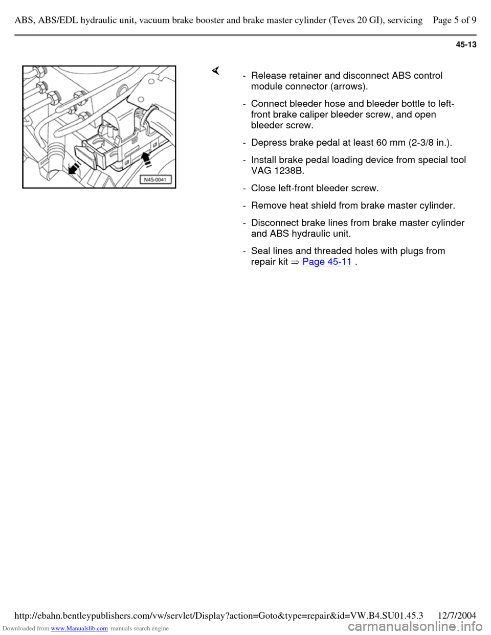
- Release retainer and disconnect ABS control
module connector (arrows).
- Connect bleeder hose and bleeder bottle to left-
front brake caliper bleeder screw, and open
bleeder screw.
- Depress brake pedal at least 60 mm (2-3/8 in.). - Install brake pedal loading device from special tool
VAG 1238B.
- Close left-front bleeder screw. - Remove heat shield from brake master cylinder. - Disconnect brake lines from brake master cylinder
and ABS hydraulic unit.
- Seal lines and threaded holes with plugs from
repair kit Page 45-11 . Page 5 of 9ABS, ABS/EDL hydraulic unit, vacuum brake booster and brake master cylinder (Teves 20 GI), servicing12/7/2004http://ebahn.bentleypublishers.com/vw/servlet/Display?action=Goto&type=repair&id=VW.B4.SU01.45.3
Page 183 of 369
Downloaded from www.Manualslib.com manuals search engine 45-14
-
Remove Torx socket-head bolts (T25) from
ABS hydraulic unit bracket.
- Remove ABS hydraulic unit/ABS control module
assembly.
- Disconnect ABS hydraulic pump connector from
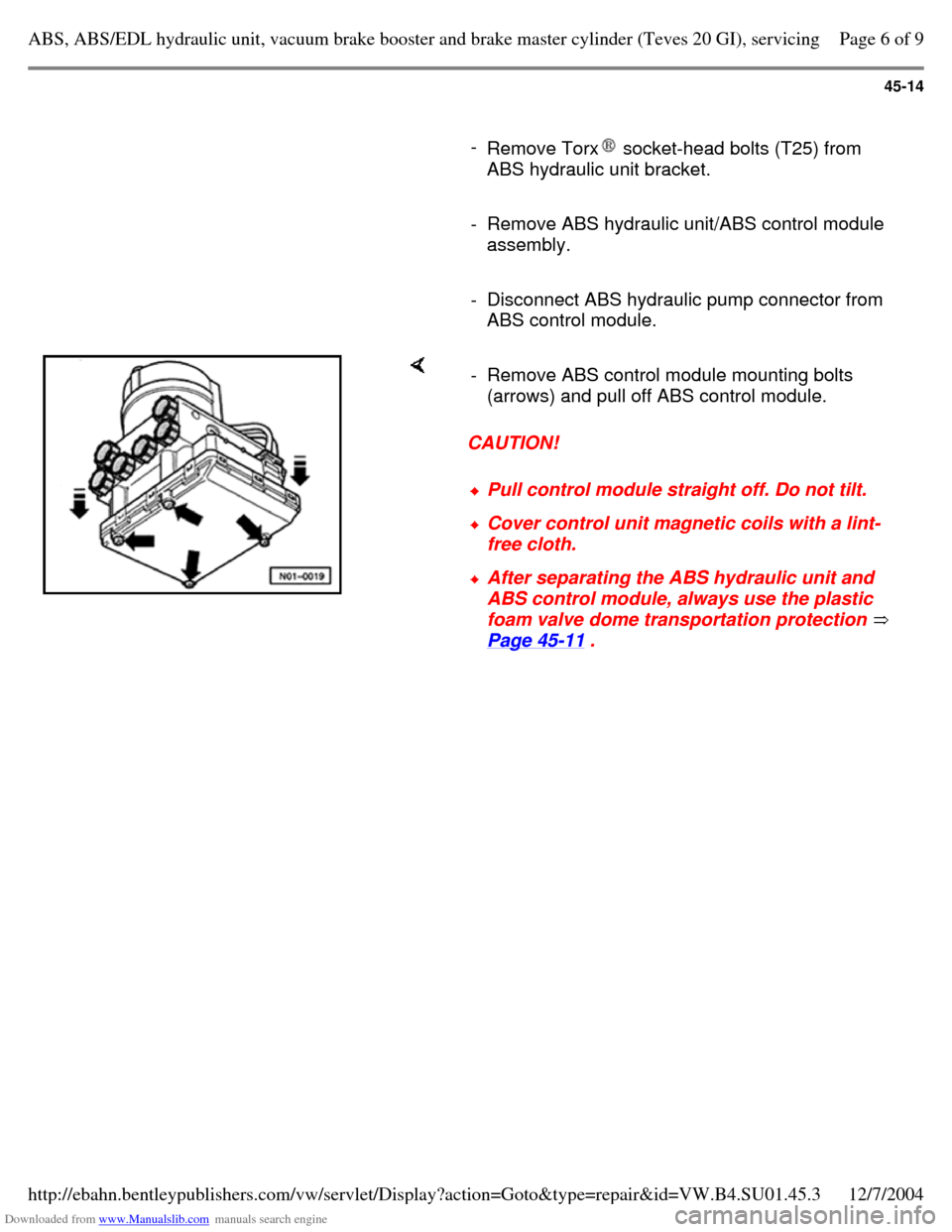
ABS control module. CAUTION! - Remove ABS control module mounting bolts
(arrows) and pull off ABS control module. Pull control module straight off. Do not tilt. Cover control unit magnetic coils with a lint-
free cloth. After separating the ABS hydraulic unit and
ABS control module, always use the plastic
foam valve dome transportation protection
Page 45-11 . Page 6 of 9ABS, ABS/EDL hydraulic unit, vacuum brake booster and brake master cylinder (Teves 20 GI), servicing12/7/2004http://ebahn.bentleypublishers.com/vw/servlet/Display?action=Goto&type=repair&id=VW.B4.SU01.45.3
Page 184 of 369
Downloaded from www.Manualslib.com manuals search engine 45-15
Installing
Note:
Remove the sealing plugs from a new ABS
hydraulic unit one at a time, and only when the
corresponding brake line is to be connected.
If the plugs are removed too soon, brake fluid
can escape and it can no longer be certain that
the unit is sufficiently filled or adequately bled.
- Mount ABS control module to hydraulic unit
using new bolts.
Tightening torque: 4 Nm (35 in lb)
- Reconnect ABS hydraulic pump connector. The remainder of the installation procedure is the
reverse of removal, with the following additions:
- Bleed brake system Page 47-29 . Page 7 of 9ABS, ABS/EDL hydraulic unit, vacuum brake booster and brake master cylinder (Teves 20 GI), servicing12/7/2004http://ebahn.bentleypublishers.com/vw/servlet/Display?action=Goto&type=repair&id=VW.B4.SU01.45.3
Page 185 of 369
Downloaded from www.Manualslib.com manuals search engine 45-16
Note:
For vehicles equipped with ABS/EDL, on which
the brake fluid reservoir has been completely
empty (e.g. leaks in brake system), it is
necessary to initiate the "Basic Setting" function
of the On Board Diagnostic (OBD) program:
Repair Manual, Brake System On Board Diagnostic (OBD), Repair Group 01 Otherwise the standard brake bleeding
procedures apply.
- Code ABS control module: Repair Manual, Brake System On Board Diagnostic (OBD), Repair Group 01
Tightening torques
ABS control unit to ABS
hydraulic unit 4 Nm (35 in.
lb)
ABS hydraulic unit to bracket
(Torx T25 socket-head bolts) 8 Nm (71 in.
lb)
Brake master cylinder to
vacuum booster 25
Nm (18 ft
lb)
Heat shield to brake master
cylinder 8 Nm (71 in.
lb)
Brake lines to ABS hydraulic
unit
M10 x 1 15
Nm (11 ft
lb)
M12 x 1 15
Nm (11 ft
lb) Page 8 of 9ABS, ABS/EDL hydraulic unit, vacuum brake booster and brake master cylinder (Teves 20 GI), servicing12/7/2004http://ebahn.bentleypublishers.com/vw/servlet/Display?action=Goto&type=repair&id=VW.B4.SU01.45.3
Page 186 of 369
Downloaded from www.Manualslib.com manuals search engine 45-17
Brake hydraulic system, bleeding and
filling
Vehicles with ABS/EDL
For vehicles with ABS/EDL, when the brake fluid
reservoir has been completely emptied (e.g. due
to leaks in the brake system) it is necessary to
initiate the "Basic Setting" function of the On
Board Diagnostic (OBD) program.
Repair Manual, Brake System On Board Diagnostic (OBD), Repair Group 01 Otherwise the standard brake bleeding
procedures apply Page 47-29 . Page 9 of 9ABS, ABS/EDL hydraulic unit, vacuum brake booster and brake master cylinder (Teves 20 GI), servicing12/7/2004http://ebahn.bentleypublishers.com/vw/servlet/Display?action=Goto&type=repair&id=VW.B4.SU01.45.3
Page 187 of 369
Downloaded from www.Manualslib.com manuals search engine 45-18
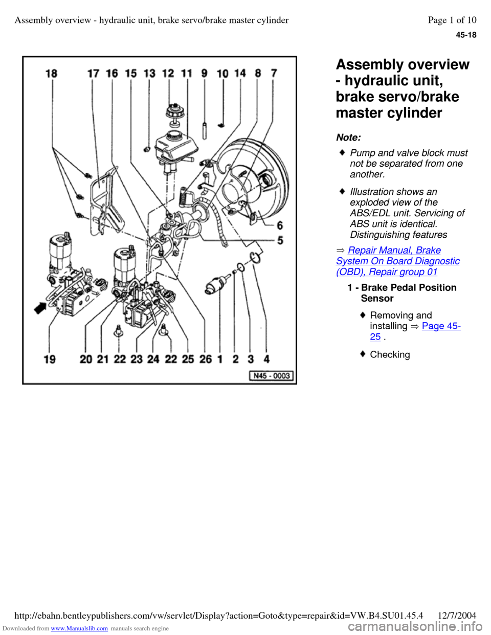
Assembly overview
- hydraulic unit,
brake servo/brake
master cylinder
Note:
Repair Manual, Brake System On Board Diagnostic (OBD), Repair group 01 Pump and valve block must
not be separated from one
another. Illustration shows an
exploded view of the
ABS/EDL unit. Servicing of
ABS unit is identical.
Distinguishing features 1 - Brake Pedal Position
Sensor Removing and
installing Page 45-25 . Checking Page 1 of 10Assembly overview - hydraulic unit, brake servo/brake master cylinder12/7/2004http://ebahn.bentleypublishers.com/vw/servlet/Display?action=Goto&type=repair&id=VW.B4.SU01.45.4
Page 189 of 369
Downloaded from www.Manualslib.com manuals search engine 45-20
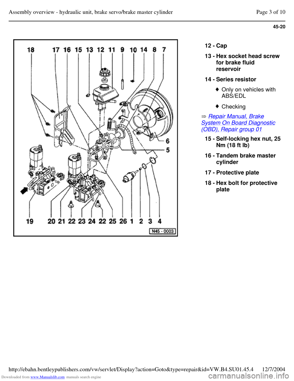
Repair Manual, Brake System On Board Diagnostic (OBD), Repair group 01 12 - Cap
13 - Hex socket head screw for brake fluid
reservoir
14 - Series resistor Only on vehicles with
ABS/EDL Checking 15 - Self-locking hex nut, 25 Nm (18 ft lb)
16 - Tandem brake master
cylinder
17 - Protective plate
18 - Hex bolt for protective
plate Page 3 of 10Assembly overview - hydraulic unit, brake servo/brake master cylinder12/7/2004http://ebahn.bentleypublishers.com/vw/servlet/Display?action=Goto&type=repair&id=VW.B4.SU01.45.4
Page 190 of 369
Downloaded from www.Manualslib.com manuals search engine 45-21
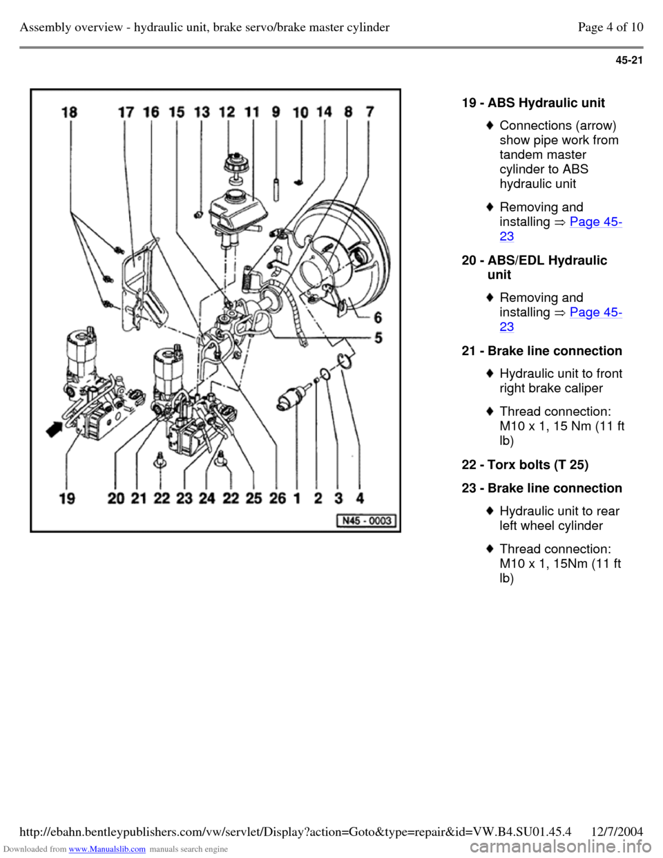
19 - ABS Hydraulic unit Connections (arrow)
show pipe work from
tandem master
cylinder to ABS
hydraulic unit Removing and
installing Page 45-23 20 - ABS/EDL Hydraulic
unit Removing and
installing Page 45-23 21 - Brake line connection Hydraulic unit to front
right brake caliper Thread connection:
M10 x 1, 15 Nm (11 ft
lb)
22 - Torx bolts (T 25)
23 - Brake line connection Hydraulic unit to rear
left wheel cylinder Thread connection:
M10 x 1, 15Nm (11 ft
lb) Page 4 of 10Assembly overview - hydraulic unit, brake servo/brake master cylinder12/7/2004http://ebahn.bentleypublishers.com/vw/servlet/Display?action=Goto&type=repair&id=VW.B4.SU01.45.4
Page 192 of 369
Downloaded from www.Manualslib.com manuals search engine 45-23
Hydraulic unit, removing and installing
Note:
For easier disassembling and assembling, it is
more practical to remove the hydraulic unit
complete with brake servo and brake master
cylinder.
Removing
- Disconnect battery Ground (GND) strap.
- Separate all electrical connections on ABS
unit.
- Remove as much brake fluid as possible from
brake fluid reservoir using a suction bottle.
- Disconnect brake lines from ABS hydraulic unit
and seal threaded holes with plugs from repair
kit, Part No. 1HO 698 311.
- Remove left-hand trim under instrument
panel.
- Disconnect brake pedal from brake servo unit
Page 46-44 . Page 6 of 10Assembly overview - hydraulic unit, brake servo/brake master cylinder12/7/2004http://ebahn.bentleypublishers.com/vw/servlet/Display?action=Goto&type=repair&id=VW.B4.SU01.45.4
Page 193 of 369
Downloaded from www.Manualslib.com manuals search engine 45-24
- Remove nuts from brake servo/bulkhead.
- Carefully remove hydraulic unit and brake servo
with brake master cylinder from engine
compartment.
Installing
Note:
Hydraulic units supplied as replacement parts
are already filled with hydraulic fluid and bled.
Only remove sealing plugs on hydraulic unit
when the relevant brake line is going to be
connected.
If the sealing plugs are removed too early,
brake fluid can escape, it is then no longer
guaranteed that the unit is sufficiently filled or
adequately bled.
- Preassemble hydraulic unit and brake servo with tandem master cylinder away from vehicle.
- Secure hydraulic unit, brake servo with tandem
master cylinder to bulkhead.
- Connect brake lines.
- Reconnect all electrical connections on ABS unit (ensure correctly connected).
- Bleed brake system Page 47-27 .
- Install left-hand trim under instrument panel. Page 7 of 10Assembly overview - hydraulic unit, brake servo/brake master cylinder12/7/2004http://ebahn.bentleypublishers.com/vw/servlet/Display?action=Goto&type=repair&id=VW.B4.SU01.45.4