indicator VOLKSWAGEN T-ROC 2019 Owners Manual
[x] Cancel search | Manufacturer: VOLKSWAGEN, Model Year: 2019, Model line: T-ROC, Model: VOLKSWAGEN T-ROC 2019Pages: 502, PDF Size: 8.58 MB
Page 4 of 502
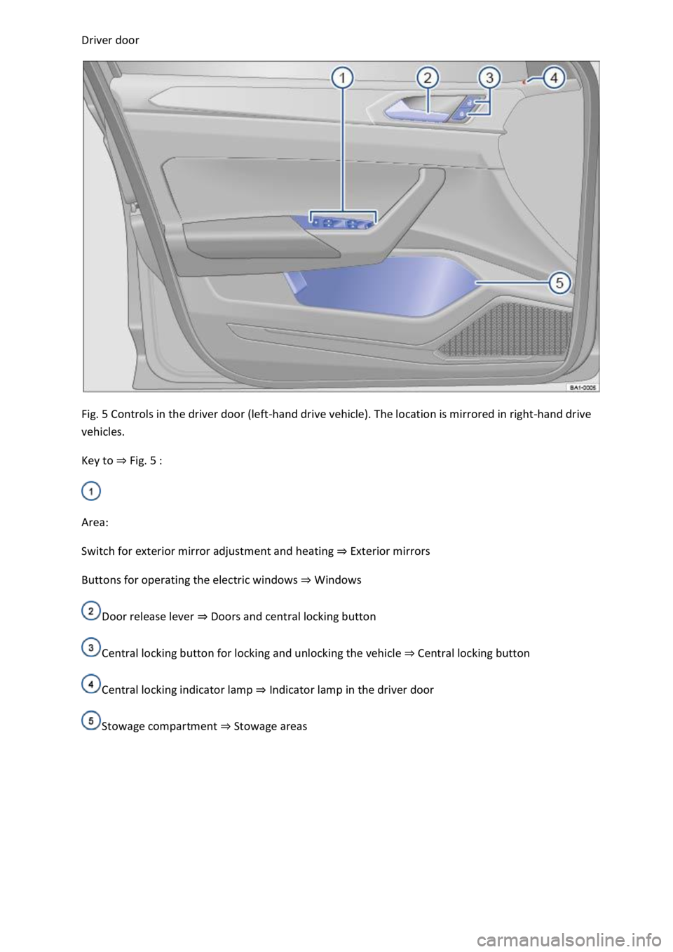
Fig. 5 Controls in the driver door (left-hand drive vehicle). The location is mirrored in right-hand drive
vehicles.
Key to Fig. 5
Area:
Switch for exterior mirror adjustment and heating Exterior mirrors
Buttons for operating the electric windows Windows
Door release lever Doors and central locking button
Central locking button for locking and unlocking the vehicle Central locking button
Central locking indicator lamp Indicator lamp in the driver door
Stowage compartment Stowage areas
Page 6 of 502

In the engine compartment
Fuse box cover Changing fuses
Lever for adjusting the steering column position Steering wheel
Light switch Vehicle lighting
Turn signal and main beam lever Vehicle lighting
With switches and buttons for the driver assist systems Button for driver assist systemsDriver
assist systems
Vents Heating and air conditioning system
Instrument cluster Instrument cluster
With warning and indicator lamps Symbols in instrument cluster
Lever for wipers and washers Wipers
With buttons for operating the menus Instrument cluster
Controls on the multifunction steering wheel:
Operating driver assist systems Operating using the multifunction steering wheelDriver assist
systems
Audio, navigation
Opening the telephone menu or accepting telephone calls
Volume adjustment
Activating voice control (no function in some models)
Horn
Location of the driver front airbag Airbag system
Ignition lock Starting and stopping the engine
Pedals Pedals
Page 8 of 502

In an emergency
Indicator lamp for the front passenger front airbag switch-off function Airbag system
Driver assist systems Driver assist systems
Controls for the air conditioning system, heating and fresh air system Heating, ventilating,
cooling
Controls for the air conditioning system, heating and fresh air system Heating, ventilating,
cooling
Key to Fig. 9
Lever:
DSG
Page 9 of 502
Front passenger side
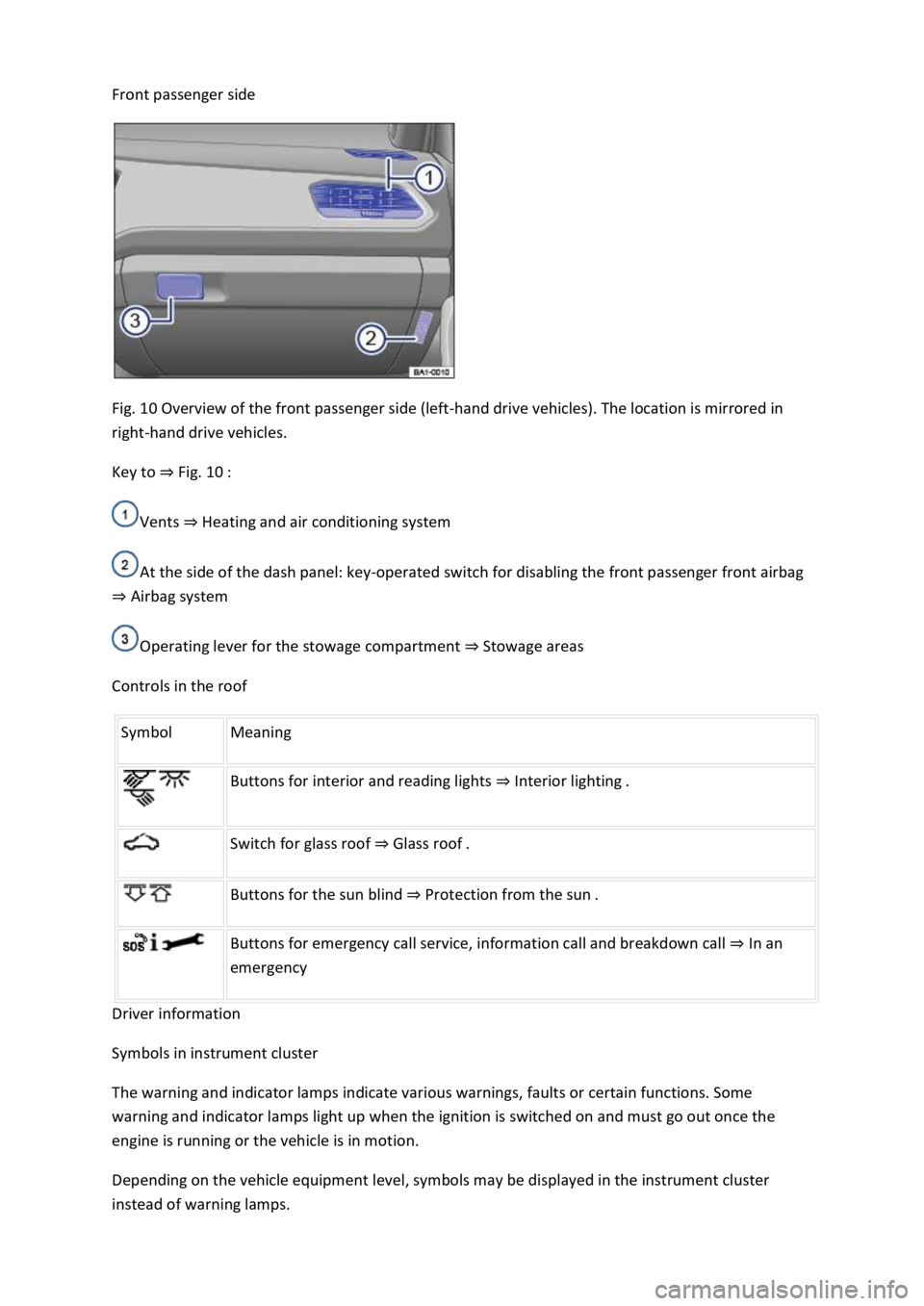
Fig. 10 Overview of the front passenger side (left-hand drive vehicles). The location is mirrored in
right-hand drive vehicles.
Key to Fig. 10
Vents Heating and air conditioning system
At the side of the dash panel: key-operated switch for disabling the front passenger front airbag
Airbag system
Operating lever for the stowage compartment Stowage areas
Controls in the roof
Symbol Meaning
Buttons for interior and reading lights Interior lighting.
Switch for glass roof Glass roof.
Buttons for the sun blind Protection from the sun.
Buttons for emergency call service, information call and breakdown call In an
emergency
Driver information
Symbols in instrument cluster
The warning and indicator lamps indicate various warnings, faults or certain functions. Some
warning and indicator lamps light up when the ignition is switched on and must go out once the
engine is running or the vehicle is in motion.
Depending on the vehicle equipment level, symbols may be displayed in the instrument cluster
instead of warning lamps.
Page 10 of 502
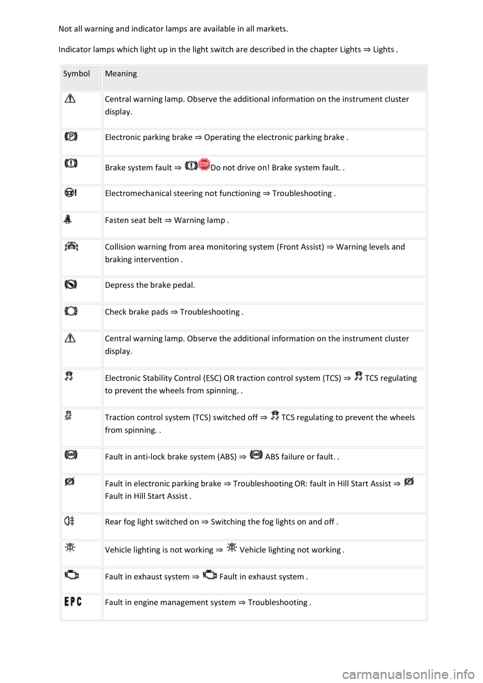
Indicator lamps which light up in the light switch are described in the chapter Lights Lig
Symbol Meaning
Central warning lamp. Observe the additional information on the instrument cluster
display.
Electronic parking brake Operating the electronic parking brake.
Brake system fault
Electromechanical steering not functioning Troubleshooting.
Fasten seat belt Warning lamp.
Collision warning from area monitoring system (Front Assist) Warning levels and
Depress the brake pedal.
Check brake pads Troubleshooting.
Central warning lamp. Observe the additional information on the instrument cluster
display.
Electronic Stability Control (ESC) OR traction control system (TCS) TCS regulating
to
Traction control system (TCS) switched off TCS regulating to prevent the wheels
Fault in anti-lock brake system (ABS)
Fault in electronic parking brake TroubleshootingOR: fault in Hill Start Assist
Rear fog light switched on Switching the fog lights on and off.
Vehicle lighting is not working
Fault in exhaust system Fault
Fault in engine management system Troubleshooting.
Page 18 of 502

or arrow button on the multifunction steering wheel to select the required
map size. A frame appears around the selected option.
Press the button on the multifunction steering wheel to confirm your selection.
With some equipment levels, navigation is shown on two screens or only one. The navigation map
can be displayed on the Active Info Display and Infotainment system or only on the Infotainment
system display. In the latter case, only navigation arrows are shown on the Active Info Display.
Displays
First read and observe the introductoryinformation and safety warnings
Possible instrument cluster displays
Open doors, bonnet and boot lid.
Warning and information messages.
Mileage displays.
Time Time
Radio and navigation information ookletInfotainment system,.
Telephone information Infotainment system,.
Outside temperature.
Compass display.
Selector lever positions.
Gear-change indicator Gear-change indicator
Driving data display (multifunction display) and menus for various settings Instrument cluster
menus
Service interval display Service interval display
Speed warning Instrument cluster menus
Speed warning for winter tyres.
Start/stop system status display Start/stop system
Road signs detected by the Dynamic Road Sign Display system Dynamic Road Sign Display (Sign
Assist)
Status display for Active Cylinder Management (ACT
Page 32 of 502
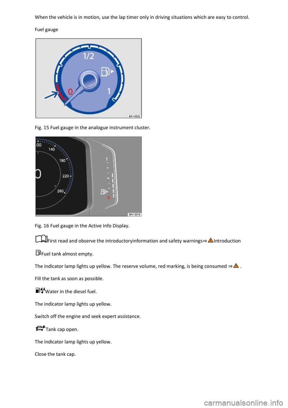
Fuel gauge
Fig. 15 Fuel gauge in the analogue instrument cluster.
Fig. 16 Fuel gauge in the Active Info Display.
First read and observe the introductoryinformation and safety warnings
Fuel tank almost empty.
The indicator lamp lights up yellow. The reserve volume, red marking, is being consumed
Fill the tank as soon as possible.
Water in the diesel fuel.
The indicator lamp lights up yellow.
Switch off the engine and seek expert assistance.
Tank cap open.
The indicator lamp lights up yellow.
Close the tank cap.
Page 34 of 502
18 Coolant temperature gauge in the Active Info Display.
First read and observe the introductory information and safety warnings
Cold area. The engine has not yet reached operating temperature. Avoid high engine revs and
heavy engine loads until the engine is warm.
Normal area.
Warning area. The temperature may also rise to the hot area when the engine is working hard,
especially at high ambient temperatures.
Coolant
The indicator lamp lights up and the central warning lamp flashes red.
The coolant level is not correct or there is a fault in the coolant system.
Do not drive on!
Stop the vehicle, switch off the engine and allow it to cool down.
Check the coolant level Coolant
Seek expert assistance if the warning lamp does not go out although the coolant level is adequate.
Service interval display
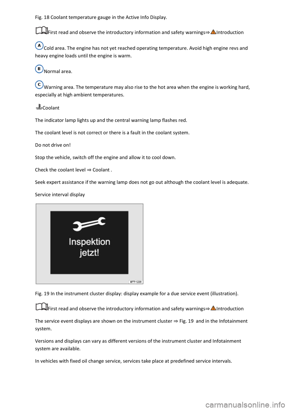
Fig. 19 In the instrument cluster display: display example for a due service event (illustration).
First read and observe the introductory information and safety warnings
The service event displays are shown on the instrument cluster Fig. 19and in the Infotainment
system.
Versions and displays can vary as different versions of the instrument cluster and Infotainment
system are available.
In vehicles with fixed oil change service, services take place at predefined service intervals.
Page 42 of 502

Fig. 23
Display areas.
Arrow buttons for changing to the lap timer.
Opening the performance monitor
Press the MENU button or function button on the Infotainment system.
Touch the Vehicle function button.
Touch the Selection function button.
Touch the Sport function button.
If you would like to switch between the performance monitor and the lap timer Lap timer
one of the arrow buttons on the left and right above the instruments Fig. 23
Selecting instruments and setting units
The display can show a maximum of three instruments at the same time. Each instrument can be
selected for each display area Fig. 23
To change between instruments, swipe vertically over the display. The currently selected instrument
will then disappear and a new instrument will appear.
The units can be adjusted for some instruments in the Infotainment system Vehicle settings
menu
The following instruments can be displayed:
Charge pressure display: the charge pressure display Fig. 23
ar). The further to the right the
needle on the scale, the higher the engine power output.
Accelerometer (G-meter): the accelerometer (G-meter) Fig. 23
-type area shows the
acceleration level and the direction of the acting force (in the opposite direction according to
physical laws). If you drive to the left, for example, the red marking will move in the right area of the
instrument (and vice versa). If you accelerate, the red marking will move down. If you brake, the red
marking will move up. The level of acceleration is indicated by the position of the red marking which
moves outwards. If the acceleration increases, the red marking will move away from the centre area.
Power display: the power display Fig. 23
Coolant temperature display: the needle may move further in a clockwise direction under high
engine loads and with high outside temperatures. This is no cause for concern unless the
indicator lamp in the instrument cluster display is lit up or flashing Coolant temperature display
Oil temperature display: the needle is in the middle area under normal driving conditions. If the
needle is in the bottom left area, this means that the engine has not yet reached its operating
temperature. Avoid excessively high speeds and acceleration when the engine has not yet reached
Page 43 of 502

needle may move further in a clockwise direction under high engine
loads and at high outside temperatures. This is no cause for concern unless the indicator lamp
in the instrument cluster display is lit up or flashing Engine oil
Adapting the display areas to the driving situation
Choose the three possible instruments corresponding to your individual driving style and the driving
situation.
WARNING
Accidents and injuries can occur if the driver is distracted. Operating the Infotainment system can
distract you from the road.
Always drive carefully and responsibly.
NOTICE
When starting from cold, avoid high engine speeds, driving at full throttle and over-loading the
engine.
Due to the principle of performance determination used in the vehicle, the physical accuracy of the
displayed values is not guaranteed.
Lap timer
First read and observe the introductoryinformation and safety warnings
The lap timer provides you with the option of timing your own laps manually in the vehicle on a race
track, storing the times and comparing them with previously measured best times.
Fig. 24 On the Infotainment system display: lap timer with stopwatch, function button and lap times.