sensor VOLKSWAGEN T-ROC 2021 Owner´s Manual
[x] Cancel search | Manufacturer: VOLKSWAGEN, Model Year: 2021, Model line: T-ROC, Model: VOLKSWAGEN T-ROC 2021Pages: 502, PDF Size: 9.42 MB
Page 264 of 502
When approaching objects at high speeds, the signals and displays of the parking systems may not
respond quickly enough to issue a warning.
Volkswagen recommends that drivers practise using the parking systems in a traffic-calmed area or
car park to allow them to familiarise themselves with the systems and their functions.
Park Distance Control
Introduction
This chapter contains information on the followingsubjects:
⇒ Switching on and off
⇒ Display representation
⇒ Troubleshooting
The Park Distance Control system assists the driver when manoeuvring and parking.
Park Distance Control detects the distance from an obstacle by means of sensors in the front and
rear areas of the vehicle. If there is an obstacle in the detection range of the sensors, the system
indicates this on the Infotainment system and by means of signal tones.
Settings
With some equipment levels, settings for Park Distance Control can be made in the Infotainment
system ⇒ Infotainment system controls and displays .
You can save some settings in the user accounts of the personalisation function. The settings change
automatically when the user account is changed ⇒ Personalisation .
Switching on and off
Fig. 127 In the centre console: button for switching Park Distance Control on and off (depending on
equipment).
First read and observe the introductoryinformation and safety warnings⇒Introduction
Switching on Park Distance Control
Press the button.
Page 266 of 502
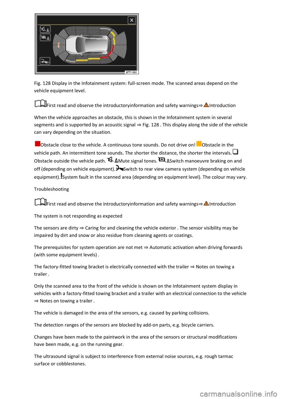
Fig. 128 Display in the Infotainment system: full-screen mode. The scanned areas depend on the
vehicle equipment level.
First read and observe the introductoryinformation and safety warnings⇒Introduction
When the vehicle approaches an obstacle, this is shown in the Infotainment system in several
segments and is supported by an acoustic signal ⇒ Fig. 128 . This display along the side of the vehicle
can vary depending on the situation.
Obstacle close to the vehicle. A continuous tone sounds. Do not drive on!Obstacle in the
vehicle path. An intermittent tone sounds. The shorter the distance, the shorter the intervals.
Obstacle outside the vehicle path.Mute signal tones.Switch manoeuvre braking on and
off (depending on vehicle equipment).Switch to rear view camera system (depending on vehicle
equipment).System fault in the scanned area (depending on equipment level). The colour may vary.
Troubleshooting
First read and observe the introductoryinformation and safety warnings⇒Introduction
The system is not responding as expected
The sensors are dirty ⇒ Caring for and cleaning the vehicle exterior . The sensor visibility may be
impaired by dirt and snow or also residue from cleaning agents or coatings.
The prerequisites for system operation are not met ⇒ Automatic activation when driving forwards
(with some equipment levels) .
The factory-fitted towing bracket is electrically connected with the trailer ⇒ Notes on towing a
trailer .
Only the scanned area to the front of the vehicle is shown on the Infotainment system display in
vehicles with a factory-fitted towing bracket and a trailer with an electrical connection to the vehicle
⇒ Notes on towing a trailer .
The vehicle is damaged in the area of the sensors, e.g. caused by parking collisions.
The detection ranges of the sensors are blocked by add-on parts, e.g. bicycle carriers.
Changes have been made to the paintwork in the area of the sensors or structural modifications
have been made, e.g. on the running gear.
The ultrasound signal is subject to interference from external noise sources, e.g. rough tarmac
surface or cobblestones.
Page 267 of 502
No sensor visibility, error message, system switches itself off
The sensor area is switched off permanently if a sensor fails.
Park Distance Control malfunctions will be indicated by a text message with an acoustic warning and
the indicator lamp in the button flashing when the system is switched on for the first time. If the
sensors are dirty or covered, the affected sensor cluster will be displayed on the Park Distance
Control screen. A cleaning message also appears (depending on the vehicle equipment level).
Possible solution
Switch off the system temporarily.
Check whether any of the causes described apply.
Clean the sensors or remove stickers or accessories from the sensors and cameras ⇒ Caring for and
cleaning the vehicle exterior .
Check whether any damage is visible.
You can switch the system back on again once you have rectified the cause of the problem.
If the system still fails to respond as expected, have the system checked by a qualified workshop or
your Volkswagen dealership.
Rear view camera system (Rear View)
Introduction
This chapter contains information on the followingsubjects:
⇒ Switching on and off
⇒ Display representation
⇒ Prerequisites
⇒ Parking
⇒ Troubleshooting
The rear view camera system in the rear of the vehicle makes it easier for the driver to see behind
the vehicle and provides support for parking manoeuvres.
The rear view camera system shows the area behind the vehicle on the Infotainment system screen.
Depending on the operating mode, orientation lines support the view to the rear.
WARNING
Using images from the camera to estimate the distance from obstacles (people, vehicles etc.) is
inaccurate and could cause accidents and severe injuries.
Camera lenses enlarge and distort the field of vision and show objects differently and inaccurately
on the screen.
Page 275 of 502

Troubleshooting
First read and observe the introductoryinformation and safety warnings⇒Introduction
The system is not responding as expected
The sensors are dirty ⇒ Caring for and cleaning the vehicle exterior . The sensor visibility may be
impaired by dirt and snow or also residue from cleaning agents or coatings.
The system requirements must be met ⇒ Prerequisites .
The sensors are covered by water.
The vehicle is damaged in the area of the sensors, e.g. caused by parking collisions.
The detection ranges of the sensors are blocked by add-on parts, e.g. bicycle carriers.
Changes have been made to the paintwork in the area of the sensors or structural modifications
have been made, e.g. on the vehicle front end or the running gear.
The ultrasound signal is subject to interference from external noise sources, e.g. rough tarmac
surface or cobblestones.
No sensor visibility, error message, system switches itself off
Park Assist is switched off if a sensor fails.
Clean the sensors or remove stickers or accessories from the sensors and cameras ⇒ Caring for and
cleaning the vehicle exterior .
Check whether any damage is visible.
Possible solution
Switch off the system temporarily.
Check whether any of the causes described apply.
You can switch the system back on again once you have rectified the cause of the problem.
If the system still fails to respond as expected, have the system checked by a qualified workshop.
Automatic cancellation of driving in/out of a parking space
Park Assist cancels parking or driving out of a parking space in the following situations:
The button is pressed.
The driver intervenes using the steering wheel.
The driver door is opened.
The parking operation is not completed within around six minutes.
There is a system fault.
TCS is switched off or is taking corrective action.
Page 277 of 502

Rear Traffic Alert monitors the traffic crossing behind the vehicle when reversing out of a parking
space or manoeuvring. Rear Traffic Alert functions using radar sensors in the rear bumper.
Key to ⇒ Fig. 134 :
Critical situation. Do not drive on!Possible critical situation.
Detection of a critical situation can also take place acoustically:
A warning signal will sound and a text message will be displayed in the instrument cluster for
vehicles without Park Distance Control.
In vehicles with Park Distance Control, an acoustic signal will sound with the continuous tone of Park
Distance Control. If the Park Distance Control is deactivated, no warning can be given to the driver
and the Rear Traffic Alert system will also be switched off temporarily.
If there is a system fault in the scanned area, the indicator lamp will light up yellow on the
instrument cluster display.
Automatic braking intervention to minimise damage
If Rear Traffic Alert detects an approaching road user and the driver has not pressed the brake, the
system can brake automatically.
Automatic braking intervention is activated when reversing at speeds of between 1–12 km/h (1–
7 mph). The vehicle is held stationary for up to two seconds after vehicle standstill has been
detected.
After automatic braking intervention is activated to prevent damage to the vehicle, the system
requires approximately ten seconds before it can activate another automatic braking intervention.
Automatic braking intervention can be interrupted by pressing the accelerator or brake pedal
sharply and taking control of the vehicle.
Automatic deactivation
Rear Traffic Alert is deactivated automatically and cannot be switched on if the factory-fitted towing
bracket is electrically connected to a trailer or similar ⇒ Notes on towing a trailer . Once a trailer is
electrically connected to the vehicle and the driver pulls away, a text message appears in the
instrument cluster display to inform the driver that Rear Traffic Alert has been deactivated. Rear
Traffic Alert will be automatically activated again when the trailer has been unhitched from the
vehicle. This applies if the functions were previously activated. Rear Traffic Alert must be switched
off manually for trailer towing if a non-factory-fitted towing bracket is used.
WARNING
The intelligent Rear Traffic Alert technology cannot overcome the laws of physics, and functions only
within the limits of the system. Do not let the assistance function of Rear Traffic Alert tempt you to
take any safety risks while driving. The system is not a substitute for the full concentration of the
driver.
Page 309 of 502
WARNING
The start/stop system must always be switched off manually when towing a trailer using towing
brackets that have not been retrofitted by Volkswagen. Otherwise faults can occur in the brake
system, possibly resulting in accidents and serious injuries.
NOTICE
Observe the instructions and information for vehicles with an N1 approval ⇒ Information about
vehicles with N1 approval (light commercial vehicle) .
Always switch off the anti-theft alarm before a trailer is hitched or unhitched or a bicycle carrier is
loaded or unloaded ⇒ Anti-theft alarm . The tilt sensor could otherwise trigger an alarm
unintentionally.
With a new engine, do not tow a trailer during the first 1,000 km ⇒ Running in the engine .
Some retrofitted towing brackets may cover the aperture for fitting the towing eye. If so, the towing
eye cannot be used for towing or tow-starting other vehicles. For this reason, the removed ball head
of a retrofitted towing bracket should be kept in the vehicle at all times.
Technical requirements
First read and observe the introductoryinformation and safety warnings⇒Introduction
Cooling system
There is an increased load on the engine and the cooling system when towing a trailer. The cooling
system must contain sufficient coolant and be able to cope with the extra load due to trailer towing.
Trailer brake
If the trailer is equipped with its own brake system, comply with the relevant regulations.
Trailer tail light clusters
The trailer tail light clusters must work correctly and meet legal requirements. Do not exceed the
maximum power consumption for the trailer.
Exterior mirrors
If you are unable to see the traffic behind the trailer using the vehicle's standard exterior mirrors,
additional exterior mirrors should be fitted in accordance with any country-specific regulations.
Before setting off, adjust the exterior mirrors so that you have a sufficient view towards the rear.
Page 349 of 502
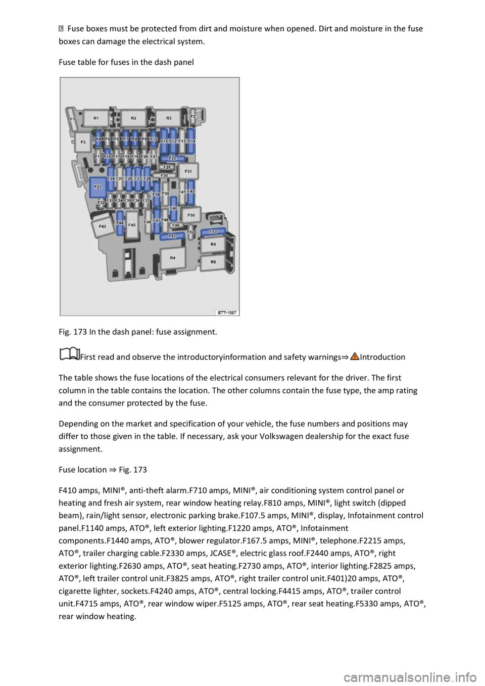
boxes can damage the electrical system.
Fuse table for fuses in the dash panel
Fig. 173 In the dash panel: fuse assignment.
First read and observe the introductoryinformation and safety warnings⇒Introduction
The table shows the fuse locations of the electrical consumers relevant for the driver. The first
column in the table contains the location. The other columns contain the fuse type, the amp rating
and the consumer protected by the fuse.
Depending on the market and specification of your vehicle, the fuse numbers and positions may
differ to those given in the table. If necessary, ask your Volkswagen dealership for the exact fuse
assignment.
Fuse location ⇒ Fig. 173
F410 amps, MINI®, anti-theft alarm.F710 amps, MINI®, air conditioning system control panel or
heating and fresh air system, rear window heating relay.F810 amps, MINI®, light switch (dipped
beam), rain/light sensor, electronic parking brake.F107.5 amps, MINI®, display, Infotainment control
panel.F1140 amps, ATO®, left exterior lighting.F1220 amps, ATO®, Infotainment
components.F1440 amps, ATO®, blower regulator.F167.5 amps, MINI®, telephone.F2215 amps,
ATO®, trailer charging cable.F2330 amps, JCASE®, electric glass roof.F2440 amps, ATO®, right
exterior lighting.F2630 amps, ATO®, seat heating.F2730 amps, ATO®, interior lighting.F2825 amps,
ATO®, left trailer control unit.F3825 amps, ATO®, right trailer control unit.F401)20 amps, ATO®,
cigarette lighter, sockets.F4240 amps, ATO®, central locking.F4415 amps, ATO®, trailer control
unit.F4715 amps, ATO®, rear window wiper.F5125 amps, ATO®, rear seat heating.F5330 amps, ATO®,
rear window heating.
Page 350 of 502
1) Note installation position. Factory-fitted fuse location as shown in illustration ⇒ Fig. 173 .
Fuse tables for fuses in the engine compartment
First read and observe the introductoryinformation and safety warnings⇒Introduction
The table shows the fuse locations of the electrical consumers relevant for the driver. The first
column in the table contains the location. The other columns contain the fuse type, the amp rating
and the consumer protected by the fuse.
Depending on the market and specification of your vehicle, the fuse numbers and positions may
differ to those given in the table. If necessary, ask your Volkswagen dealership for the exact fuse
assignment.
F65 amps, ATO®, brake light sensor.F1440 amps, JCASE®, windscreen heating.F1515 amps, ATO®,
horn.F1930 amps, ATO®, front wipers.F3720 amps, ATO®, auxiliary heater.
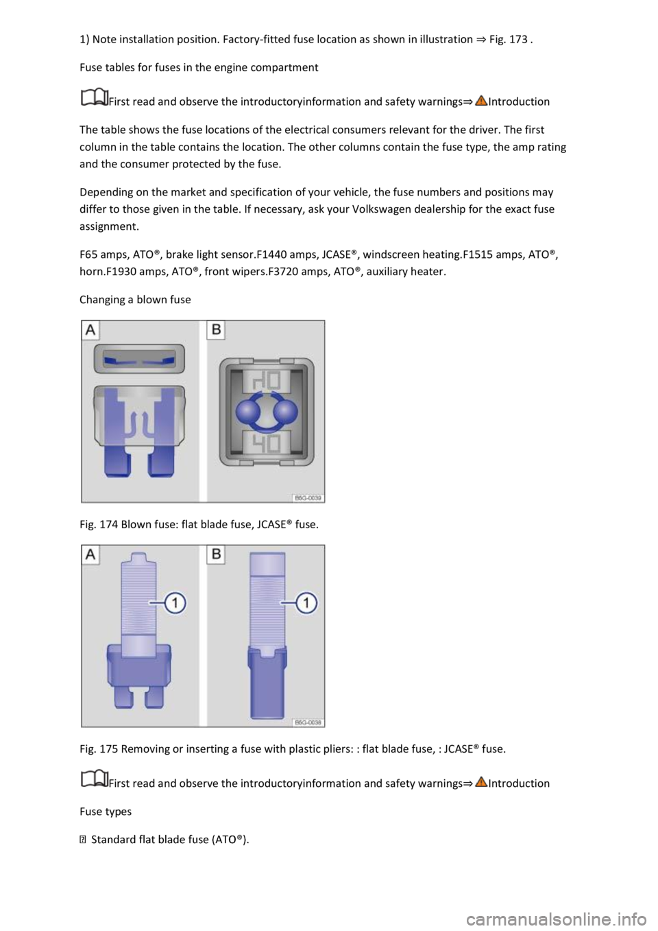
Changing a blown fuse
Fig. 174 Blown fuse: flat blade fuse, JCASE® fuse.
Fig. 175 Removing or inserting a fuse with plastic pliers: : flat blade fuse, : JCASE® fuse.
First read and observe the introductoryinformation and safety warnings⇒Introduction
Fuse types
Page 377 of 502
correct openings. The use of incorrect service fluids could result in serious malfunctions and engine
damage.
The engine oil level must never be above area ⇒ Fig. 186 Ⓑ. Otherwise oil can be drawn in through
the crankcase breather and escape into the atmosphere via the exhaust system.
Troubleshooting
First read and observe the introductoryinformation and safety warnings⇒Introduction
and Engine oil pressure too low
The central warning lamp lights up red and the text message Stop vehicle. Oil pressure. Observe
vehicle wallet is displayed.
Do not drive on!
Switch off the engine and check the engine oil level. Checking the engine oil level ⇒ Checking the
engine oil level and refilling the engine oil . - Do not drive on or allow the engine to run if the
warning lamp is flashing although the engine oil level is correct. The engine could otherwise be
damaged. Seek expert assistance.
and Engine oil level too low
The central warning lamp lights up red and the text message Refill engine oil. is displayed.
Engine oil level is too low. Switch off the engine.
Checking the engine oil level ⇒ Checking the engine oil level and refilling the engine oil .
and Engine oil level low
The central warning lamp lights up yellow and the text message Check oil level. is displayed.
Engine oil level is low. Switch off the engine.
Checking the engine oil level ⇒ Checking the engine oil level and refilling the engine oil .
and Fault in engine oil system
The central warning lamp lights up yellow and the text message Oil sensor: workshop. is displayed.
Engine oil system is faulty. Go to a qualified workshop and have the engine oil sensor checked.
and Engine oil level too high
The central warning lamp lights up yellow and the text message Reduce oil level. is displayed.
Engine oil level is too high. Switch off the engine.
Check the engine oil level. Checking the engine oil level ⇒ Checking the engine oil level and refilling
the engine oil . Seek expert assistance.
Page 391 of 502
Fault in the alternator. The 12-volt vehicle battery will not be charged by the alternator while the
vehicle is in motion.
Switch off any electrical consumers that are not required. Inform a qualified workshop. Have the
electrical system checked.
The start/stop system cannot start the engine ⇒ Start/stop system .
and vehicle battery (12-volt)
The central warning lamp lights up yellow and the text message 12 V battery low. Charge by driving.
is displayed.
The charge level of the vehicle battery is insufficient.
Recharge the 12-volt vehicle battery by driving the vehicle for an extended time.
The start/stop system cannot start the engine ⇒ Start/stop system .
and vehicle battery (12-volt)
The central warning lamp lights up red and the text message Replace 12 V battery. Workshop. is
displayed.
The vehicle battery condition is not ok.
Seek expert assistance and have the battery checked and replaced if necessary.
The start/stop system cannot start the engine ⇒ Start/stop system .
Wheels and tyres
Tyre monitoring system
Introduction
This chapter contains information on the followingsubjects:
⇒ Tyre Pressure Loss Indicator
⇒ Troubleshooting for Tyre Pressure Loss Indicator
The tyre monitoring system warns the driver when the tyre pressures are too low.
The tyre monitoring system monitors various parameters (for example, rolling circumference) of all
wheels using ABS sensors (indirect measurement).
WARNING
The intelligent tyre monitoring system technology cannot overcome the laws of physics, and
functions only within the limits of the system. Incorrect handling of the wheels and tyres can lead to
a sudden loss of pressure in the tyres, tread separation and even tyre blow-out.