VOLKSWAGEN TIGUAN 2017 Owner´s Manual
Manufacturer: VOLKSWAGEN, Model Year: 2017, Model line: TIGUAN, Model: VOLKSWAGEN TIGUAN 2017Pages: 341, PDF Size: 9.14 MB
Page 301 of 341
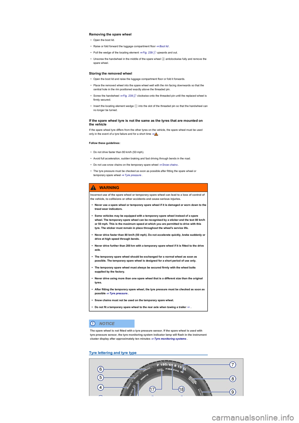
Removing the spare wheel
•Open the boot lid.
•Raise or fold forward the luggage compartment floor ⇒ Boot lid.
•Pull the wedge of the locating element ⇒ Fig. 239① upwards and out.
•Unscrew the handwheel in the middle of the spare wheel ② anticlockwise fully and remove the
spare wheel.
Storing the removed wheel
•Open the boot lid and raise the luggage compartment floor or fold it forwards.
•Place the removed wheel into the spare wheel well with the rim facing downwards so that the
central hole in the rim positioned exactly above the threaded pin.
•Screw the handwheel ⇒ Fig. 239② clockwise onto the threaded pin until the replaced wheel is
firmly secured.
•Insert the locating element wedge ① into the slot of the threaded pin so that the handwheel can
no longer be turned.
If the spare wheel tyre is not the same as the tyres that are mounted on
the vehicle
If the spare wheel tyre differs from the other tyres on the vehicle, the spare wheel must be used
only in the event of a tyre failure and for a short time ⇒.
Follow these guidelines:
•Do not drive faster than 80 km/h (50 mph).
•Avoid full acceleration, sudden braking and fast driving through bends in the road.
•Do not use snow chains on the temporary spare wheel ⇒ Snow chains.
•The tyre pressure must be checked as soon as possible after fitting the spare wheel or
temporary spare wheel ⇒ Tyre pressure.
Tyre lettering and tyre type
Incorrect use of the spare wheel or temporary spare wheel can lead to a loss of control of
the vehicle, to collisions or other accidents and cause serious injuries.
•Never use a spare wheel or temporary spare wheel if it is damaged or worn down to the
tread wear indicators.
•Some vehicles may be equipped with a temporary spare wheel instead of a spare
wheel. The temporary spare wheel can be recognised by a sticker and the text 80 km/h
or 50 mph. This is the maximum speed at which you are permitted to drive with this
tyre. The sticker must remain in place throughout the wheel's service life.
•Never drive faster than 80 km/h (50 mph). Do not accelerate quickly, brake suddenly or
drive at high speed through bends.
•Never drive further than 200 km with a temporary spare wheel if it is fitted to the drive
axle.
•The temporary spare wheel should be exchanged for a normal wheel as soon as
possible. The temporary spare wheel is designed for a short period of use only.
•The temporary spare wheel must always be secured firmly with the wheel bolts
supplied by the factory.
•Never drive using more than one spare wheel that is a different size than the original
tyres.
•After fitting the temporary spare wheel, the tyre pressure must be checked as soon as
possible ⇒ Tyre pressure.
•Snow chains must not be used on the temporary spare wheel.
•Do not fit a temporary spare wheel to the rear axle when towing a trailer ⇒.
WARNING
The spare wheel is not fitted with a tyre pressure sensor. If the spare wheel is used with
tyre pressure sensor, the tyre monitoring system indicator lamp will flash in the instrument
cluster display after approximately ten minutes ⇒ Tyre monitoring systems.
NOTICE
Page 302 of 341
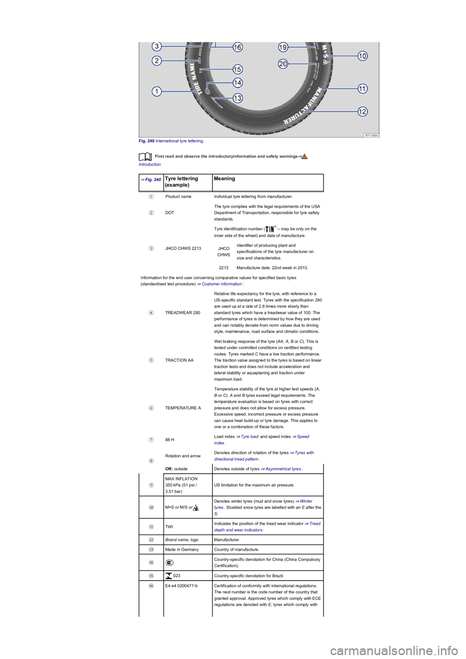
Fig. 240 International tyre lettering.
First read and observe the introductoryinformation and safety warnings⇒
Introduction
⇒ Fig. 240Tyre lettering
(example)
Meaning
①Product nameIndividual tyre lettering from manufacturer.
②DOT
The tyre complies with the legal requirements of the USA
Department of Transportation, responsible for tyre safety
standards.
③JHCO CHWS 2213
Tyre identification number ( – may be only on the
inner side of the wheel) and date of manufacture:
JHCO
CHWS
Identifier of producing plant and
specifications of the tyre manufacturer on
size and characteristics.
2213Manufacture date: 22nd week in 2013.
Information for the end user concerning comparative values for specified basic tyres
(standardised test procedure) ⇒ Customer information:
④TREADWEAR 280
Relative life expectancy for the tyre, with reference to a
US-specific standard test. Tyres with the specification 280
are used up at a rate of 2.8 times more slowly than
standard tyres which have a treadwear value of 100. The
performance of tyres is determined by how they are used
and can notably deviate from norm values due to driving
style, maintenance, road surface and climatic conditions.
⑤TRACTION AA
Wet braking response of the tyre (AA, A, B or C). This is
tested under controlled conditions on certified testing
routes. Tyres marked C have a low traction performance.
The traction value assigned to the tyres is based on linear
traction tests and does not include acceleration and
lateral stability or aquaplaning and traction under
maximum load.
⑥TEMPERATURE A
Temperature stability of the tyre at higher test speeds (A,
B or C). A and B tyres exceed legal requirements. The
temperature evaluation is based on tyres with correct
pressure and does not allow for excess pressure.
Excessive speed, incorrect pressure or excess pressure
can cause heat build-up or tyre damage. This applies to
one or a combination of these factors.
⑦88 HLoad index ⇒ Tyre load and speed index ⇒ Speed
index.
⑧
Rotation and arrowDenotes direction of rotation of the tyres ⇒ Tyres with
directional tread pattern.
OR: outsideDenotes outside of tyres ⇒ Asymmetrical tyres.
⑨
MAX INFLATION
350 kPa (51 psi /
3.51 bar)
US limitation for the maximum air pressure.
⑩M+S or M/S or
Denotes winter tyres (mud and snow tyres) ⇒ Winter
tyres. Studded snow tyres are labelled with an E after the
S.
⑪TWIIndicates the position of the tread wear indicator ⇒ Tread
depth and wear indicators.
⑫Brand name, logoManufacturer.
⑬Made in GermanyCountry of manufacture.
⑭Country-specific denotation for China (China Compulsory
Certification).
⑮ 023Country-specific denotation for Brazil.
⑯E4 e4 0200477-bCertification of conformity with international regulations.
The next number is the code number of the country that
granted approval. Approved tyres which comply with ECE
regulations are denoted with E, tyres which comply with
a)
Page 303 of 341
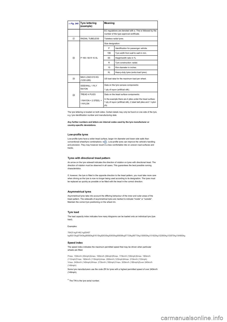
⇒ Fig. 240Tyre lettering
(example)
Meaning
EC regulations are denoted with e. This is followed by the
number of the type approval certificate.
⑰RADIAL TUBELESSTubeless radial tyres.
⑱P 195 / 65 R 15 XL
Size designation:
PIdentification for passenger vehicle.
195Tyre width from wall to wall in mm.
65Height/width ratio in %.
RTyre construction: radial.
15Rim diameter in inches.
XLHeavy-duty tyres (extra load tyres).
⑲MAX LOAD 615 KG
(1235 LBS)US load data for the maximum load per wheel.
⑳
SIDEWALL 1 PLY
RAYON
Data on the tyre carcass components:
1 ply of rayon (artificial silk).
TREAD 4 PLIESData on the tread surface components:
1 RAYON + 2 STEEL +
1 NYLON
In the example there are 4 plies under the tread surface:
1 ply of rayon (artificial silk), 2 steel belt plies and 1 nylon
ply.
The tyre lettering is located on both sides. Certain labels may only be found on one side of the tyre,
e.g. tyre identification number and manufacturing date.
Any further numbers and letters are internal codes used by the tyre manufacturer or
country-specific denotations.
Low-profile tyres
Low-profile tyres have a wider tread surface, larger rim diameter and lower side walls than
conventional wheel/tyre combinations ⇒. Low-profile tyres can improve the vehicle's handling
and precision. They may however result in a less comfortable ride on uneven road surfaces and
tracks.
Tyres with directional tread pattern
An arrow on the tyre sidewall indicates the direction of rotation on tyres with directional tread. The
direction of rotation must be observed in all cases. This guarantees the best possible running
characteristics.
If, however, the tyre is fitted in the opposite direction to the tread pattern, you must take more care
when driving as the tyre is now no longer being used according to its designation. The tyres must
be replaced as quickly as possible or be fitted with the tread in the correct direction.
Asymmetrical tyres
Asymmetrical tyres take into account the differing behaviour of the inner and outer areas of the
tread pattern. The sidewalls of asymmetrical tyres are marked to indicate "inside" or "outside".
Maintain the correct tyre positioning on the wheel rim.
Tyre load
The load capacity index indicates how many kilograms can be loaded onto an individual tyre (tyre
load).
Examples:
78425 kg81462 kg83487
kg85515kg87545kg88560kg91615kg92630kg93650kg95690kg97730kg99775kg100800kg101825kg102850kg103875kg104900kg
Speed index
The speed index indicates the maximum permitted speed that may be driven when particular
wheels are fitted.
Pmax. 150km/h (93mph)Qmax. 160km/h (99mph)Rmax. 170km/h (106mph)Smax. 180km/h
(112mph)Tmax. 190km/h (118mph)Umax. 200km/h (125mph)Hmax. 210km/h (130mph)
Vmax. 240km/h (149mph)Wmax. 270km/h (168mph)Ymax. 300km/h (186mph)Zover 240km/h
(149mph)
Some tyre manufacturers use the code ZR for tyres with a highest permitted speed of over 240km/h
(149mph).
The TIN is the tyre serial number.a)
Page 304 of 341
Maximum load and speed range for tyres
First read and observe the introductoryinformation and safety warnings⇒
Introduction
Vehicles in the EU and the so-called EU user states are issued an EC Certificate of Conformity.
This details the size, diameter and speed range of all tyres approved by Volkswagen for the
relevant vehicle type.
The type plate shows whether there is an EC certificate of conformity for this particular vehicle. The
type plate can be seen on the lower part of the door pillar when the door is open ⇒ Technical data.
•If the type plate has a row marked Permit then the vehicle does have an EC certificate of
conformity.
•If there is no type plate, or no row marked Permit the vehicle does not have an EC certificate of
conformity.
Winter tyres
First read and observe the introductoryinformation and safety warnings⇒
Introduction
Winter or all-year tyres improve the handling and brake response in winter conditions. Volkswagen
recommends that winter tyres be fitted to the vehicle at temperatures below +7°C (+45°F) or in
winter road conditions.
Winter tyres and all-year tyres lose a large degree of their effectiveness for winter conditions when
the tread is worn down to a depth of 4 mm.
The following applies when using winter tyres:
•Observe any country-specific legal requirements.
•Use winter tyres on all four wheels at the same time.
•Only use in winter road conditions.
•Only use the sizes of tyre that have been approved for the vehicle.
•Winter tyres must have the same belt type, size and the same tread pattern.
•Observe the maximum speed permitted by the speed index ⇒.
Speed limitation
Winter tyres have a speed limit depending on the speed index ⇒ Tyre lettering and tyre type.
Speed warning settings can be made and adjusted in the Infotainment system using the
button and the and Tyres function buttons ⇒ Operation and display in the
Infotainment system.
If you use V-rated tyres, the speed limits and required tyre pressure will be determined by the
engine size. You must ask a Volkswagen dealership about the maximum permitted speed and
required tyre pressure.
Four-wheel drive (4MOTION)
Thanks to its four-wheel drive, the vehicle will have plenty of traction in winter conditions, even with
the standard tyres. Nevertheless, Volkswagen still recommends that winter tyres or all-year tyres
should be fitted on all 4 wheels in winter, mainly because this will give a better braking response.
Observe information on snow chains⇒ Snow chains.
Summer tyres should be fitted in good time at the end of the winter. The vehicle handling is
better if summer tyres are fitted at temperatures above +7°C (+45°F). They are quieter, do not wear
so quickly and reduce fuel consumption.
In vehicles with a Tyre Pressure Loss Indicator, the system has to re-synchronise after
wheels are changed ⇒ Tyre monitoring systems.
Volkswagen dealerships can provide details on permissible winter tyre sizes.
The improved winter driving characteristics afforded by the winter tyres should not
encourage you to take any risks.
•Adapt your speed and driving style to suit visibility, weather, road and traffic
conditions.
•Never exceed the top speed and load permitted for the winter tyres that are fitted.
WARNING
Page 305 of 341
Snow chains
First read and observe the introductoryinformation and safety warnings⇒
Introduction
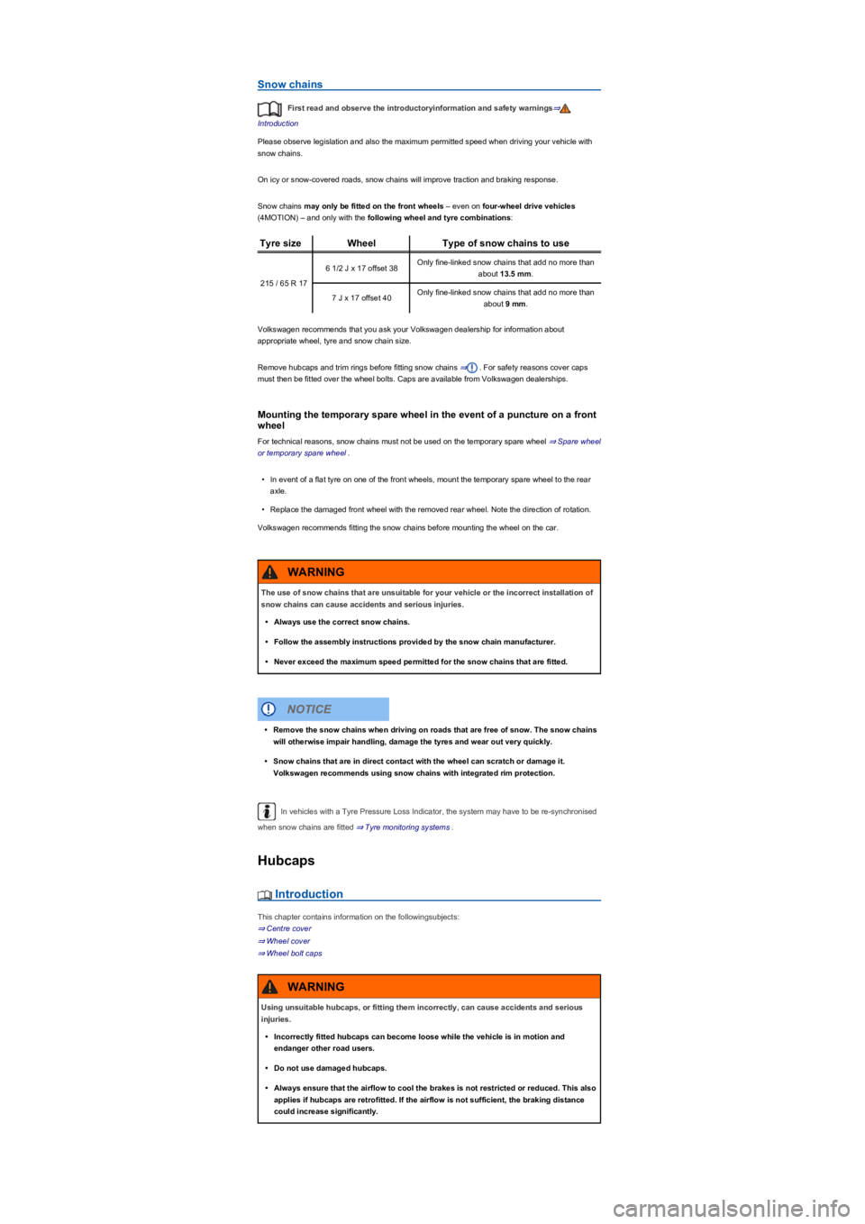
Please observe legislation and also the maximum permitted speed when driving your vehicle with
snow chains.
On icy or snow-covered roads, snow chains will improve traction and braking response.
Snow chains may only be fitted on the front wheels – even on four-wheel drive vehicles
(4MOTION) – and only with the following wheel and tyre combinations:
Tyre sizeWheelType of snow chains to use
215 / 65 R 17
6 1/2 J x 17 offset 38Only fine-linked snow chains that add no more than
about 13.5 mm.
7 J x 17 offset 40Only fine-linked snow chains that add no more than
about 9 mm.
Volkswagen recommends that you ask your Volkswagen dealership for information about
appropriate wheel, tyre and snow chain size.
Remove hubcaps and trim rings before fitting snow chains ⇒. For safety reasons cover caps
must then be fitted over the wheel bolts. Caps are available from Volkswagen dealerships.
Mounting the temporary spare wheel in the event of a puncture on a front
wheel
For technical reasons, snow chains must not be used on the temporary spare wheel ⇒ Spare wheel
or temporary spare wheel.
•In event of a flat tyre on one of the front wheels, mount the temporary spare wheel to the rear
axle.
•Replace the damaged front wheel with the removed rear wheel. Note the direction of rotation.
Volkswagen recommends fitting the snow chains before mounting the wheel on the car.
In vehicles with a Tyre Pressure Loss Indicator, the system may have to be re-synchronised
when snow chains are fitted ⇒ Tyre monitoring systems.
Hubcaps
Introduction
This chapter contains information on the followingsubjects:
⇒ Centre cover
⇒ Wheel cover
⇒ Wheel bolt caps
The use of snow chains that are unsuitable for your vehicle or the incorrect installation of
snow chains can cause accidents and serious injuries.
•Always use the correct snow chains.
•Follow the assembly instructions provided by the snow chain manufacturer.
•Never exceed the maximum speed permitted for the snow chains that are fitted.
WARNING
•Remove the snow chains when driving on roads that are free of snow. The snow chains
will otherwise impair handling, damage the tyres and wear out very quickly.
•Snow chains that are in direct contact with the wheel can scratch or damage it.
Volkswagen recommends using snow chains with integrated rim protection.
NOTICE
Using unsuitable hubcaps, or fitting them incorrectly, can cause accidents and serious
injuries.
•Incorrectly fitted hubcaps can become loose while the vehicle is in motion and
endanger other road users.
•Do not use damaged hubcaps.
•Always ensure that the airflow to cool the brakes is not restricted or reduced. This also
applies if hubcaps are retrofitted. If the airflow is not sufficient, the braking distance
could increase significantly.
WARNING
Page 306 of 341
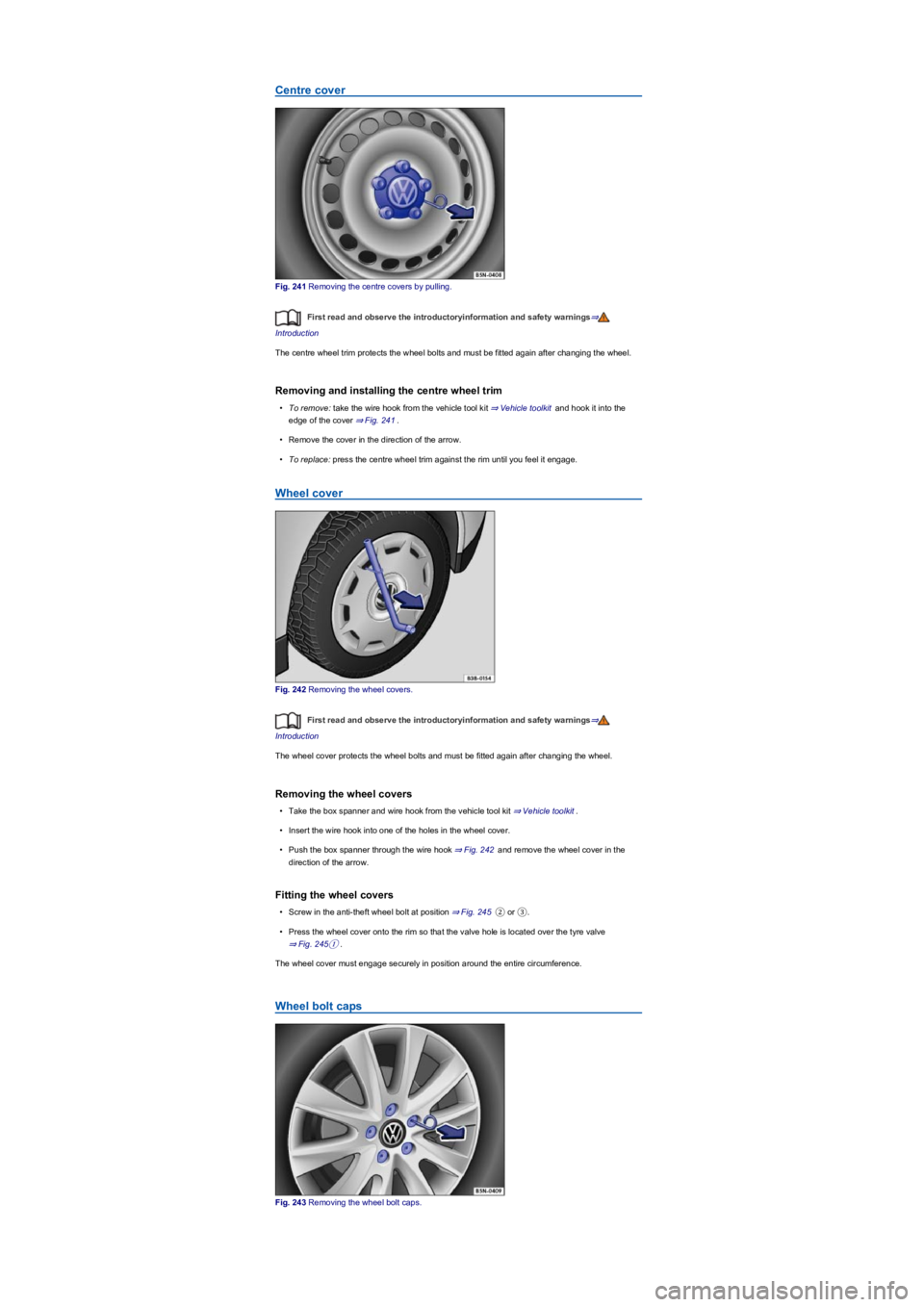
Centre cover
Fig. 241 Removing the centre covers by pulling.
First read and observe the introductoryinformation and safety warnings⇒
Introduction
The centre wheel trim protects the wheel bolts and must be fitted again after changing the wheel.
Removing and installing the centre wheel trim
•To remove: take the wire hook from the vehicle tool kit ⇒ Vehicle toolkit and hook it into the
edge of the cover ⇒ Fig. 241.
•Remove the cover in the direction of the arrow.
•To replace: press the centre wheel trim against the rim until you feel it engage.
Wheel cover
Fig. 242 Removing the wheel covers.
First read and observe the introductoryinformation and safety warnings⇒
Introduction
The wheel cover protects the wheel bolts and must be fitted again after changing the wheel.
Removing the wheel covers
•Take the box spanner and wire hook from the vehicle tool kit ⇒ Vehicle toolkit.
•Insert the wire hook into one of the holes in the wheel cover.
•Push the box spanner through the wire hook ⇒ Fig. 242 and remove the wheel cover in the
direction of the arrow.
Fitting the wheel covers
•Screw in the anti-theft wheel bolt at position ⇒ Fig. 245② or ③.
•Press the wheel cover onto the rim so that the valve hole is located over the tyre valve
⇒ Fig. 245①.
The wheel cover must engage securely in position around the entire circumference.
Wheel bolt caps
Fig. 243 Removing the wheel bolt caps.
Page 307 of 341
If your vehicle has a flat tyre, park the vehicle on a firm and level surface at a safe distance
from moving traffic.
Switch on the electronic parking brake Parking and manoeuvring.
With a DSG® dual clutch gearbox, move the selector lever to position P DSG® dual clutch
gearbox.
Stop the engine and remove the key from the ignition Starting and stopping the engine.
Manual gearbox: select a gear Manual gearbox: selecting a gear.
First read and observe the introductoryinformation and safety warnings⇒
Introduction
The caps protect the wheel bolts and should be placed fully back in position after changing the
wheel.
Removing and fitting the caps
•Removing: take the wire hook from the vehicle tool kit ⇒ Vehicle toolkit.
•Insert the wire hook through the opening in the cap ⇒ Fig. 243 and pull off in the direction of
the arrow.
•Fitting: press the caps on the bolts as far as they will go.
The anti-theft wheel bolt has a separate cap. It only fits onto the anti-theft wheel bolts and not
onto conventional wheel bolts.
Changing a wheel
Introduction
This chapter contains information on the followingsubjects:
⇒ Preparations for changing a wheel
⇒ Wheel bolts
⇒ Lifting the vehicle with the jack
⇒ Changing a wheel
⇒ After changing a wheel
Some models are delivered from the factory without a jack or box spanner. If this is the case, the
wheel should be changed by a qualified workshop.
The vehicle jack supplied with the vehicle is only designed for changing a wheel when one vehicle
tyre is damaged and has to be replaced. If both tyres on one side of the vehicle, both tyres on one
axle, or all tyres are damaged, seek expert assistance.
Preparations for changing a wheel
First read and observe the introductoryinformation and safety warnings⇒
Introduction
Checklist
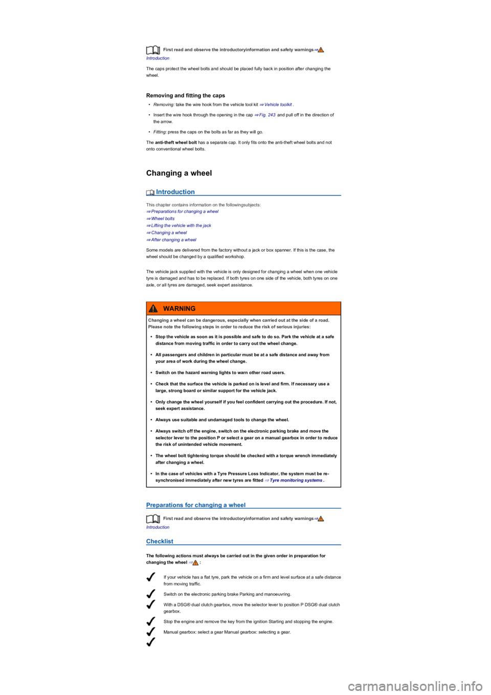
The following actions must always be carried out in the given order in preparation for
changing the wheel ⇒:
Changing a wheel can be dangerous, especially when carried out at the side of a road.
Please note the following steps in order to reduce the risk of serious injuries:
•Stop the vehicle as soon as it is possible and safe to do so. Park the vehicle at a safe
distance from moving traffic in order to carry out the wheel change.
•All passengers and children in particular must be at a safe distance and away from
your area of work during the wheel change.
•Switch on the hazard warning lights to warn other road users.
•Check that the surface the vehicle is parked on is level and firm. If necessary use a
large, strong board or similar support for the vehicle jack.
•Only change the wheel yourself if you feel confident carrying out the procedure. If not,
seek expert assistance.
•Always use suitable and undamaged tools to change the wheel.
•Always switch off the engine, switch on the electronic parking brake and move the
selector lever to the position P or select a gear on a manual gearbox in order to reduce
the risk of unintended vehicle movement.
•The wheel bolt tightening torque should be checked with a torque wrench immediately
after changing a wheel.
•In the case of vehicles with a Tyre Pressure Loss Indicator, the system must be re-
synchronised immediately after new tyres are fitted ⇒ Tyre monitoring systems.
WARNING
Page 308 of 341
Ask all vehicle occupants to leave the vehicle and stand at a safe distance away from moving
traffic.
Chock the wheel diagonally opposite the wheel being worked on with a stone, collapsible
chocks or another suitable object.
When towing a trailer: unhitch the trailer from the vehicle and park it properly .
Remove any items of luggage from the luggage compartment.
Remove the spare wheel or temporary spare wheel and the vehicle tool kit from the
luggage compartment.
Remove the hubcaps Hubcaps.
Wheel bolts
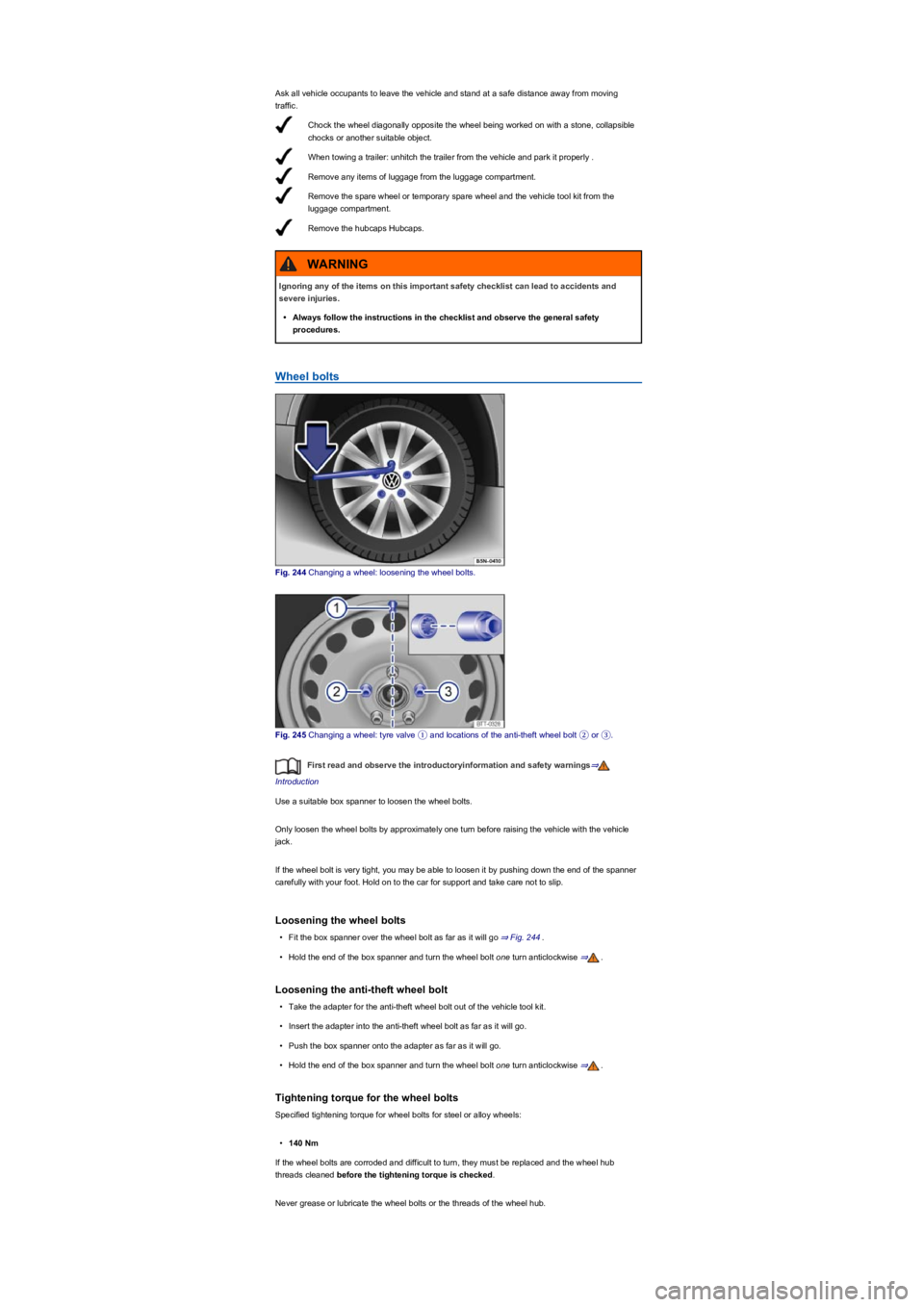
Fig. 244 Changing a wheel: loosening the wheel bolts.
Fig. 245 Changing a wheel: tyre valve ① and locations of the anti-theft wheel bolt ② or ③.
First read and observe the introductoryinformation and safety warnings⇒
Introduction
Use a suitable box spanner to loosen the wheel bolts.
Only loosen the wheel bolts by approximately one turn before raising the vehicle with the vehicle
jack.
If the wheel bolt is very tight, you may be able to loosen it by pushing down the end of the spanner
carefully with your foot. Hold on to the car for support and take care not to slip.
Loosening the wheel bolts
•Fit the box spanner over the wheel bolt as far as it will go ⇒ Fig. 244.
•Hold the end of the box spanner and turn the wheel bolt one turn anticlockwise ⇒.
Loosening the anti-theft wheel bolt
•Take the adapter for the anti-theft wheel bolt out of the vehicle tool kit.
•Insert the adapter into the anti-theft wheel bolt as far as it will go.
•Push the box spanner onto the adapter as far as it will go.
•Hold the end of the box spanner and turn the wheel bolt one turn anticlockwise ⇒.
Tightening torque for the wheel bolts
Specified tightening torque for wheel bolts for steel or alloy wheels:
•140 Nm
If the wheel bolts are corroded and difficult to turn, they must be replaced and the wheel hub
threads cleaned before the tightening torque is checked.
Never grease or lubricate the wheel bolts or the threads of the wheel hub.
Ignoring any of the items on this important safety checklist can lead to accidents and
severe injuries.
•Always follow the instructions in the checklist and observe the general safety
procedures.
WARNING
Page 309 of 341
Find a firm and level surface suitable for lifting the vehicle.
Stop the engine, with a manual gearbox select a gear or with a DSG® dual clutch gearbox
move the selector lever to position P DSG® dual clutch gearbox and switch on the
electronic parking brake Parking and manoeuvring.
Chock both wheels on the opposite side of the vehicle using the collapsible chocks or
other suitable objects.
Loosen the wheel bolts Wheel bolts.
Find the jacking point under the vehicle which is closest to the wheel that is being
changed.
Insert the hand crank into the opening on the jack (depending on equipment).
Crank up the jack until it just fits under the jacking point of the vehicle.
Ensure that the entire surface of the foot of the jack is resting securely on the ground, and
that the foot of the jack is positioned fully underneath the point of application and .
Position the jack and simultaneously continue to crank the claw up until it is in position
around the vertical rib underneath the vehicle .
The tightening torque should be checked with a properly functioning torque wrench immediately
after changing a wheel.
Lifting the vehicle with the jack
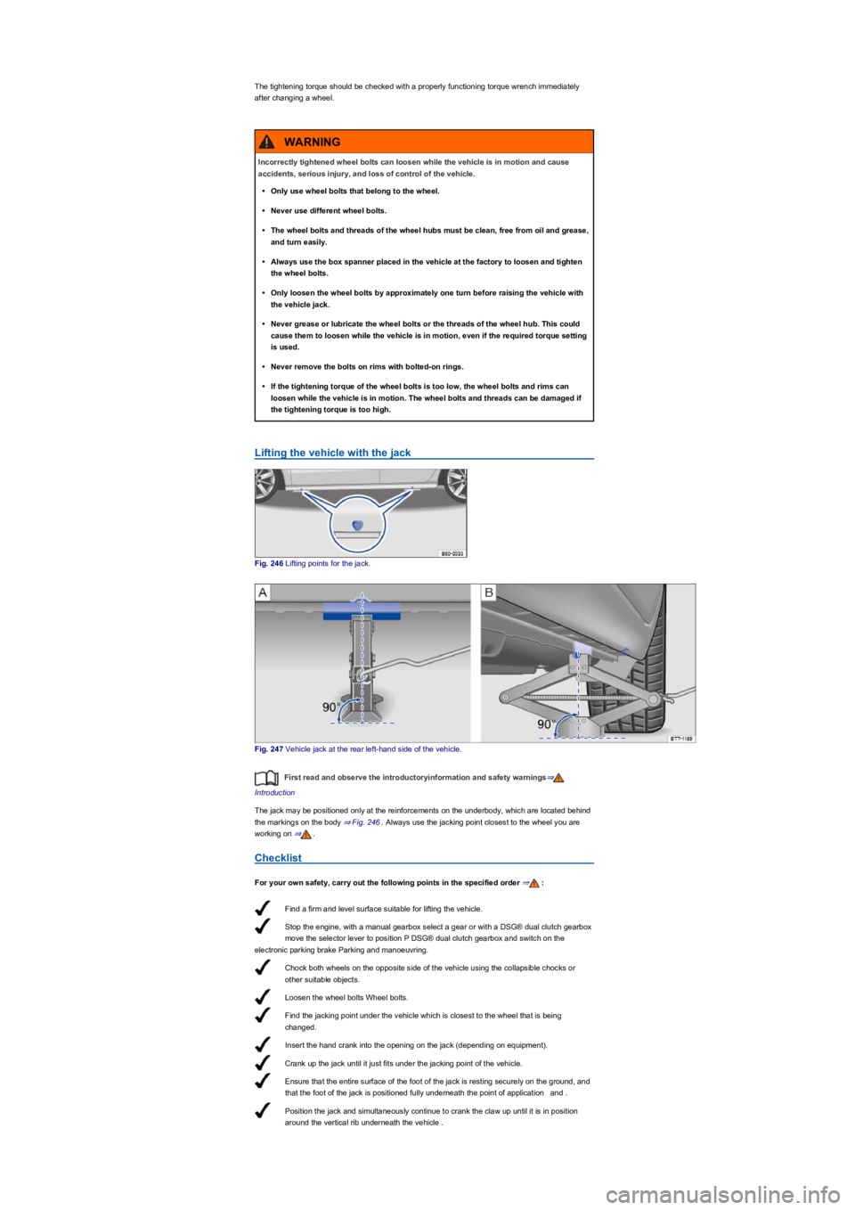
Fig. 246 Lifting points for the jack.
Fig. 247 Vehicle jack at the rear left-hand side of the vehicle.
First read and observe the introductoryinformation and safety warnings⇒
Introduction
The jack may be positioned only at the reinforcements on the underbody, which are located behind
the markings on the body ⇒ Fig. 246. Always use the jacking point closest to the wheel you are
working on ⇒.
Checklist
For your own safety, carry out the following points in the specified order ⇒:
Incorrectly tightened wheel bolts can loosen while the vehicle is in motion and cause
accidents, serious injury, and loss of control of the vehicle.
•Only use wheel bolts that belong to the wheel.
•Never use different wheel bolts.
•The wheel bolts and threads of the wheel hubs must be clean, free from oil and grease,
and turn easily.
•Always use the box spanner placed in the vehicle at the factory to loosen and tighten
the wheel bolts.
•Only loosen the wheel bolts by approximately one turn before raising the vehicle with
the vehicle jack.
•Never grease or lubricate the wheel bolts or the threads of the wheel hub. This could
cause them to loosen while the vehicle is in motion, even if the required torque setting
is used.
•Never remove the bolts on rims with bolted-on rings.
•If the tightening torque of the wheel bolts is too low, the wheel bolts and rims can
loosen while the vehicle is in motion. The wheel bolts and threads can be damaged if
the tightening torque is too high.
WARNING
Page 310 of 341
Crank the jack further until the wheel is just clear of the ground.
Changing a wheel
Fig. 248 Changing the wheel: removing the wheel bolts with the screwdriver handle.
First read and observe the introductoryinformation and safety warnings⇒
Introduction
Removing the wheel
•Observe the checklist ⇒ Preparations for changing a wheel.
•Loosen the wheel bolts ⇒ Wheel bolts.
•Jack up the vehicle ⇒ Lifting the vehicle with the jack.
•Using the hexagon socket in the screwdriver handle ⇒ Fig. 248, completely unscrew the
loosened wheel bolts and place them on a clean surface.
•Remove the wheel.
Fitting the spare wheel or temporary spare wheel
Note the tyre direction of rotation ⇒ Tyre lettering and tyre type.
•Put the wheel in place.
•Screw in the anti-theft wheel bolt using the adapter at position ⇒ Fig. 245② or ③ and tighten it
slightly in a clockwise direction.
•Screw in all the other wheel bolts in clockwise direction and tighten them slightly.
•Lower the vehicle with the jack.
•Use the box spanner to tighten all the wheel bolts securely in a clockwise direction ⇒. Do
not tighten the bolts in clockwise or anticlockwise sequence. Tighten them in diagonal
sequence.
•Fit the caps, wheel centre trim or wheel cover ⇒ Hubcaps.
Incorrect use of the vehicle jack can cause the vehicle to slip off the jack, which can lead
to severe injuries. Please note the following to help reduce the risk of injuries:
•Only use vehicle jacks that have been approved by Volkswagen for your vehicle type.
Other vehicle jacks could slip out of position – this includes vehicle jacks supplied
with other Volkswagen models.
•The ground must be firm and level. Soft ground or surfaces at an incline under the
vehicle jack may cause the vehicle to slip off the jack. If necessary use a large, strong
board or similar support for the vehicle jack.
•On a hard, slippery surface (such as tiles) use a rubber mat or similar to prevent the
vehicle jack from slipping.
•Fit the vehicle jack only at the points described. The jack claw must securely grip the
vertical rib under the side member ⇒ Fig. 247.
•Never place any part of your body (e.g. an arm or leg) underneath the vehicle if the
latter is only supported by the vehicle jack.
•If you have to work underneath the vehicle, use suitable stands to provide extra
support for the vehicle.
•Never lift the vehicle when the engine is running, or if the vehicle is tilted to the side or
on a gradient.
•Never start the engine when the vehicle is raised on a vehicle jack. Engine vibrations
can cause the vehicle to fall off the vehicle jack.
WARNING
Ignoring any of the items on this important safety checklist can lead to accidents and
severe injuries.
•Always follow the instructions in the checklist and observe the general safety
procedures.
WARNING