fuse VOLKSWAGEN TRANSPORTER 2020 Owners Manual
[x] Cancel search | Manufacturer: VOLKSWAGEN, Model Year: 2020, Model line: TRANSPORTER, Model: VOLKSWAGEN TRANSPORTER 2020Pages: 486, PDF Size: 69.28 MB
Page 3 of 486
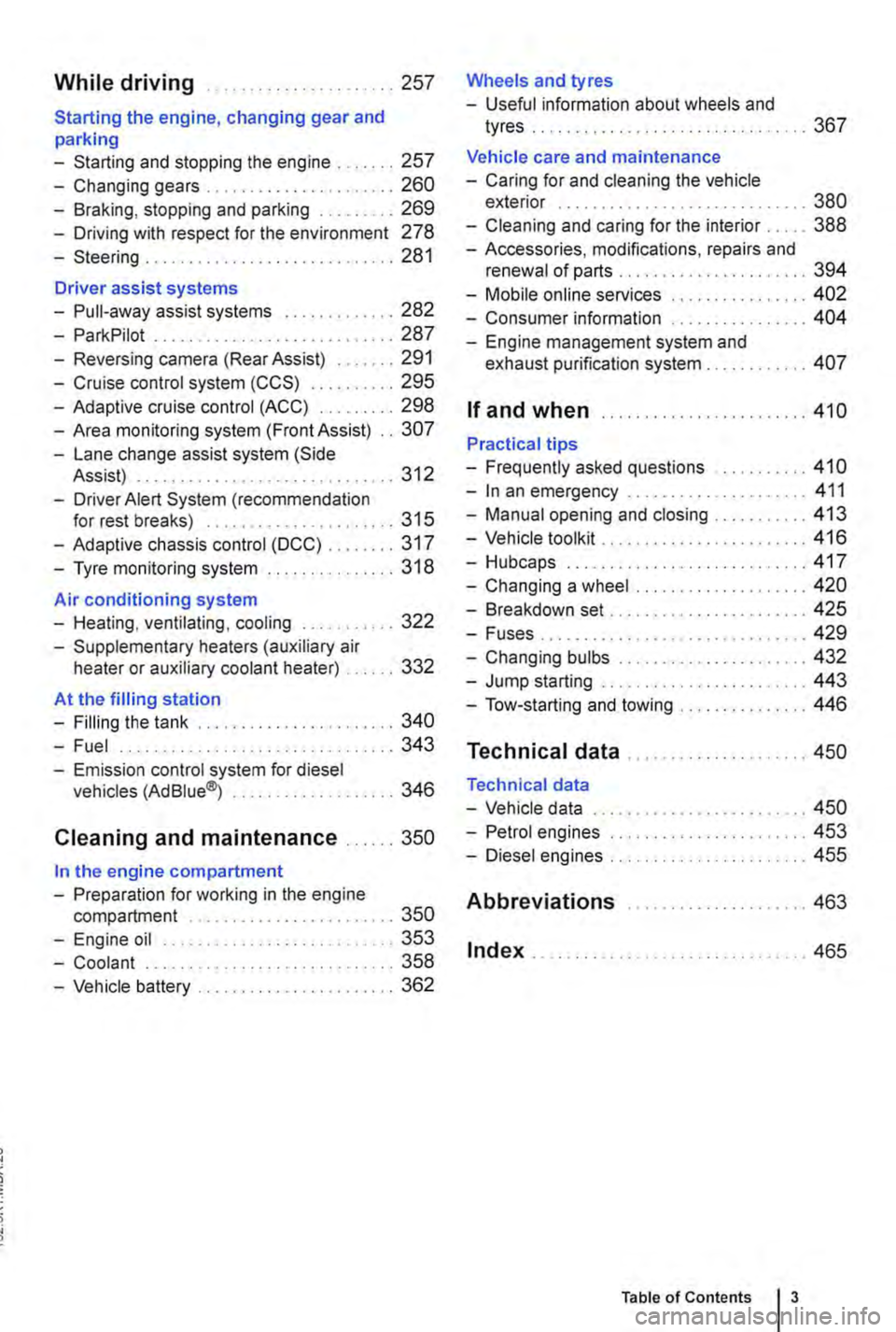
While driving .. ...... 257
Starting the engine, changing gear and parking
-Starting and stopping the engine .. 257
-Changing gears . . . . . . . . . .......... 260
-Braking, stopping and parking ......... 269
-Driving with respect for the environment 278
-Steering ........... 281
Driver assist systems
-Pull-away assist systems .... 282
-ParkPilot ............................ 287
-Reversing camera (Rear Assist) ....... 291
-Cruise control system (CCS) . . . . . ... 295
-Adaptive cruise control (ACC) ......... 298
-Area monitoring system (Front Assist) .. 307
-Lane change assist system (Side Assist) . .. . . .. .. . . . . . . . . .......... 312
-Driver Alert System (recommendation for rest breaks) . . . . . . . . . . ......... 315
-Adaptive chassis control (DCC) ........ 317
-Tyre monitoring system . . . . . . . ....... 318
Air conditioning system
-Heating, ventilating, cooling ........... 322
-Supplementary heaters (auxiliary air heater or auxiliary coolant heater) .... 332
At the filling station
-Filling the tank ....................... 340
-Fuel . . . . . . . . . . . . . . . . ........ 343
-Emission control system for diesel vehicles (AdBiue®j ................... 346
Cleaning and maintenance ...... 350
In the engine compartment
-Preparation for working in the engine compartment . . . . . . . . . . . . . . . . 350
-Engine oil ........................... 353
-Coolant ..................... 358
-Vehicle battery ....................... 362
Wheels and tyres
-Useful information about wheels and
tyres . . . . . . . . . . . . . . ..... 367
Vehicle care and maintenance
-Caring for and cleaning the vehicle exterior . . . . . . . . . . . . . . . . . . . ... 380
-Cleaning and caring for the interior ..... 388
-Accessories, modifications, repairs and renewal of parts . . . . . . . .... 394
-Mobile online services .. 402
-Consumer information 404
-Engine management system and exhaust purification system . . . .. 407
If and when ........................ 410
Practical tips
-Frequently asked questions ........... 410
-In an emergency ..................... 411
-Manual opening and closing . . . . . . . . . 413
-Vehicle toolkit . . ............... 416
-Hubcaps.. . .................... 417
-Changing a wheel .................... 420
-Breakdown set ....................... 425
-Fuses................ . . 429
-Changing bulbs . . . . . . . . .....•.... 432
-Jump starting . . . . . . .......... 443
-Tow-starting and towing . . . 446
Technical data ...
Technical data
-Vehicle data
-Petrol engines
-Diesel engines ..
Abbreviations
Index .......... .
... 450
... 450
......... 453
455
..... " ... 463
.. 465
Table of Contents 3
Page 108 of 486
@ Main beam headlights switched on &. The indicator lamp m in the instrument cluster lights up.
Pull the lever briefly in the direction of the ar-row @to switch off the main beam headlights.
@ Operate headlight flasher. The headlight flash-er comes on for as long as the lever is pulled. The indicator lamp ID lights up.
Lane change flash
To operate the lane change flash, push the lever up or down to the point where you incur resistance and then release the lever. The turn signal flashes three times.
This lane change flash function can be deactivated at a qualified workshop.
A WARNING
Incorrect use of turn signals, a failure to use turn signals, or forgetting to switch off a turn signal can confuse other road users. This can lead to accidents and serious Injuries.
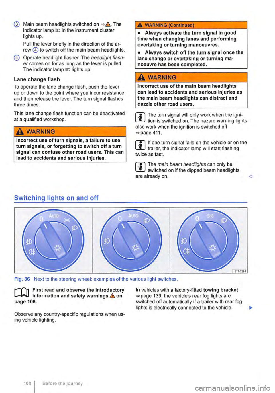
Switching lights on and off
A WARNING (Continued)
• Always activate the turn signal In good time when changing lanes and performing overtaking or turning manoeuvres.
• Always switch off the turn signal once the lane change or overtaking or turning ma-noeuvre has been completed.
A WARNING
Incorrect use of the main beam headlights can lead to accidents and serious Injuries as the main beam headlights can distract and dazzle other road users.
m The turn signal will only work when the igni-m lion is switched on. The hazard warning lights also work when the ignition is switched off 411.
m If one turn signal fails on the vehicle or on the m trailer, the indicator lamp will start flashing twice as fast.
m The main beam headlights can only be m switched on if the dipped beam headlights are already on.
l"'""'rT1 First read and observe the Introductory L--J,::.,U information and safety warnings & on page 106.
Observe any country-specific regulations when us-ing vehicle lighting.
1081 Before the; journey
In vehicles with a factory-fitted towing bracket 139, the vehicle's rear fog lights are switched off automatically if a trailer with rear fog lights is electrically connected to the vehicle. .,.
Page 134 of 486
t"""""fl1 First read and observe the introductory l..--bll information and safety warnings & on page 133.
Removing plastic covers
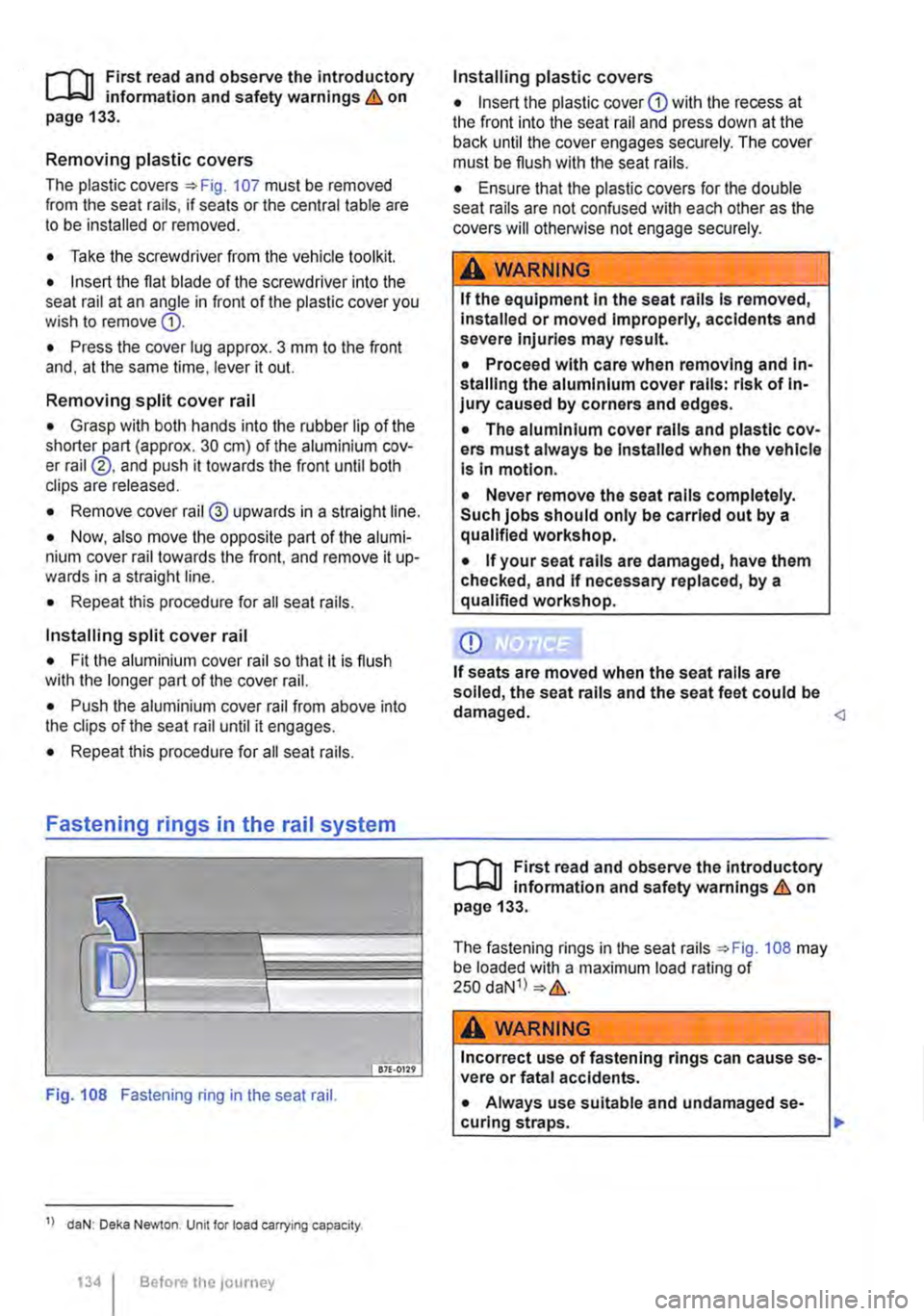
The plastic covers=:. Fig. 107 must be removed from the seat rails, if seats or the central table are to be installed or removed.
• Take the screwdriver from the vehicle tootkit.
• Insert the flat blade of the screwdriver into the seat rail at an angle in front of the plastic cover you wish to remove G).
• Press the cover lug approx. 3 mm to the front and, at the same time, lever it out.
Removing split cover rail
• Grasp with both hands into the rubber lip of the shorter part (approx. 30 cm) of the aluminium cov-er rail ®. and push it towards the front until both clips are released.
• Remove cover rail@ upwards in a straight line.
• Now, also move the opposite part of the alumi-nium cover rail towards the front, and remove it up-wards in a straight line.
• Repeat this procedure for all seat rails.
Installing split cover rail
• Fit the aluminium cover rail so that it is flush with the longer part of the cover rail.
• Push the aluminium cover rail from above into the clips of the seat rail until it engages.
• Repeat this procedure for all seat rails.
Fastening rings in the rail system
Fig. 108 Fastening ring in the seat rail.
1> daN: Deka Newton. Unit for load carrying capacity.
134 Before the JOUrney
Installing plastic covers
• Insert the plastic cover CD with the recess at the front into the seat rail and press down at the back until the cover engages securely. The cover must be flush with the seat rails.
• Ensure that the plastic covers for the double seat rails are not confused with each other as the covers will otherwise not engage securely.
A WARNING
If the equipment In the seat rails Is removed, Installed or moved Improperly, accidents and severe Injuries may result.
• Proceed with care when removing and In-stalling the aluminium cover rails: risk of In-jury caused by corners and edges.
• The aluminium cover rails and plastic cov-ers must always be Installed when the vehicle Is In motion.
• Never remove the seat rails completely. Such jobs should only be carried out by a qualified workshop.
• If your seat rails are damaged, have them checked, and If necessary replaced, by a qualified workshop.
CD
If seats are moved when the seat rails are soiled, the seat rails and the seat feet could be damaged.
The fastening rings in the seat rails ::.Fig. 108 may be loaded with a maximum load rating of 250 daN1l ::.&.
A wARNING
Incorrect use of fastening rings can cause se-vere or fatal accidents.
• Always use suitable and undamaged se-curing straps. ..,.
Page 153 of 486
A WARNING
Objects that are not secured, or are secured Incorrectly, can cause serious Injuries In the event of a sudden driving or braking manoeu·
Torch behind front passenger seat
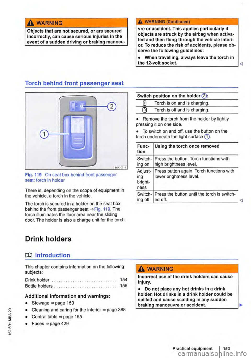
Fig. 119 On seat box behind front passenger seat: torch in holder
There is, depending on the scope of equipment in the vehicle, a torch in the vehicle.
The torch is secured in a holder on the seat box behind the front passenger seat 119. The torch illuminates the floor area near the sliding door. The holder is also a charge unit for the torch.
Drink holders
CQJ Introduction
This chapter contains information on the following subjects:
Drink holder . . . . . . . . . . . . . . . . . . . . . . . . . . . . 154
Bottle holders . . . . . . . . . . . . . . . . . . . . . . . . . 155
Additional information and warnings:
• Stowage 150
• Cleaning and caring for the interior 388
• Central table 155
0: • Fuses =>page 429
"'
A WARNING (Continued)
vre or accident. This applies particularly if objects are struck by the airbag when activa-ted and then flung through the vehicle interi· or. To reduce the risk of accidents, please ob-serve the following guidelines:
• When travelling, always leave the torch in the 12-volt socket.
Switch position on the holder@:
CD Torch is on and is charging.
@) Torch is off and is charging.
• Remove the torch from the holder by lightly pressing it on one side.
• To switch on and off, use the button on the torch underneath the light surface G).
Func-Using the torch once removed tion
Switch-Press the button. Torch functions with ing on high brightness level.
Adjust-Press button again. Torch functions with ing lower brightness level. bright-ness
Switch-Press the button until the torch is switch-ing off ed off.
A WARNING
Incorrect use of the drink holders can cause Injury.
• Do not place any hot drinks in a drink holder. Hot drinks in a drink holder could be spilled and cause scalding In any sudden braking manoeuvre or accident. .,.
Practical equipment 153
Page 155 of 486
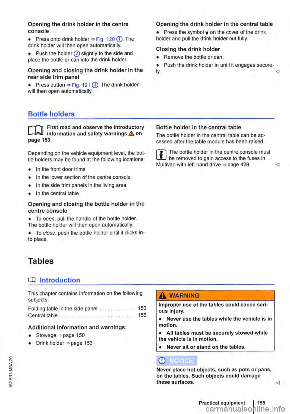
Opening the drink holder in the centre console
• Press onto drink holder "'Fig. 120 G). The drink holder will then open automatically.
• Push the holder® slightly to the side and place the bottle or can into the drink holder.
Opening and closing the drink holder in the rear side trim panel
• Press button "'Fig. 121 G). The drink holder will then open automatically.
Bottle holders
1"'111 First read and observe the introductory L-J,::.ll information and safety warnings & on page 153.
Depending on the vehicle equipment level, the bot-tle holders may be found at the following locations:
• In the front door trims
• In the lower section of the centre console
• In the side trim panels in the living area.
• In the central table
Opening and closing the bottle holder in the centre console
• To open, pull the handle of the bottle holder. The bottle holder will then open automatically.
• To close, push the bottle holder until it clicks in-to place.
Tables
o:::n Introduction
This chapter contains information on the following subjects:
Folding table in the side panel . . . . . . • . . . . . . 156 Central table . . . . . . . . . . . . 156
Additional information and warnings:
• Stowage "'page 150
• Drink holder 153
Opening the drink holder in the central table
• Press lhe symbol i on the cover of the drink holder and pull the drink holder out fully.
Closing the drink holder
• Remove the bottle or can.
• Push the drink holder in until it engages secure-
Bottle holder in the central table
The bottle holder in the central table can be ac-cessed after the table module has been raised.
m The bottle holder in the centre console must W be removed to gain access to the fuses in Multivan with left-hand drive 429.
A WARNING
Improper use of the tables could cause seri-ous injury.
• Never use the tables while the vehicle is in motion.
• All tables must be securely stowed while the vehicle is In motion.
• Never sit or stand on the tables.
CD
Never place hot objects, such as pots or pans, on the tables. Such objects could damage these surfaces.
Practical equipment 155
Page 161 of 486
Switching the cool box on and off
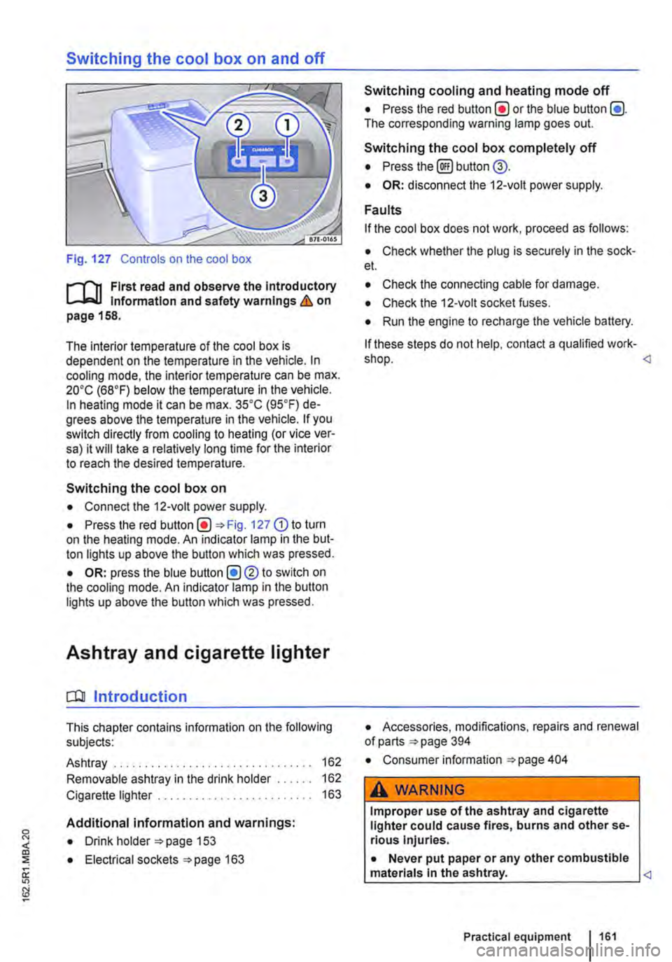
Fig. 127 Controls on the cool box
r-f'n First read and observe the Introductory Information and safety warnings & on page 158.
The interior temperature of the cool box is dependent on the temperature in the vehicle. In cooling mode, the interior temperature can be max. 20•c (68°F) below the temperature in the vehicle. In heating mode it can be max. 35•c (95.F) de-grees above the temperature in the vehicle. If you switch directly from cooling to heating (or vice ver-sa) it will take a relatively long time for the interior to reach the desired temperature.
Switching the cool box on
• Connect the 12-volt power supply.
• Press the red Fig. 127 G) to turn on the heating mode. An indicator lamp in the but-ton lights up above the button which was pressed.
• OR: press the blue button (!)®to switch on the cooling mode. An indicator lamp in the button lights up above the button which was pressed.
Ashtray and cigarette lighter
o:n Introduction
This chapter contains information on the following subjects:
Ashtray . . . . . . . . . . . . . . . . . . . 162
Removable ashtray in the drink holder 162
Cigarette lighter . . . . . . . . . . . . . . . . . . . 163
Additional information and warnings:
• Drink holder 153
• Electrical sockets 163
Switching cooling and heating mode off
• Press the red button(!) or the blue button (!). The corresponding warning lamp goes out.
Switching the cool box completely off
• Press the@) button @.
• OR: disconnect the 12-volt power supply.
Faults
If the cool box does not work, proceed as follows:
• Check whether the plug is securely in the sock-et.
• Check the connecting cable for damage.
• Check the 12-volt socket fuses.
• Run the engine to recharge the vehicle battery.
If these steps do not help, contact a qualified work-shop.
• Consumer information 404
A WARNING
Improper use of the ashtray and cigarette lighter could cause fires, burns and other se-rious Injuries.
• Never put paper or any other combustible materials In the ashtray.
Page 192 of 486
Equipment, California
Vehicle overview, California
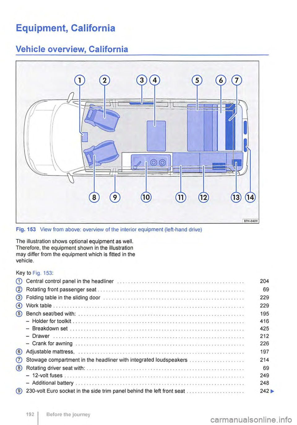
Fig. 153 View from above: overview of the interior equipment (left-hand drive)
The illustration shows optional equipment as well. Therefore, the equipment shown in the illustration may differ from the equipment which is fitted in the vehicle.
Key to Fig. 153:
CD Central control panel in the headliner . . . . . . . . . . . . . . . . . . . . . . . . . • . . . . . . . . . . . . . . . . . . . . 204
® Rotating front passenger seat . . . . . . . . . . . . . . . . . . . . . . . . . . . . . . . . . . . . . . . . . . . . . . . . . . . 69
@ Folding table in the sliding door . . . . . . . . . . . . . . . . . . . . . . . . . . . . . . . . . . . . . . . . . . . . . . 229
@ Work table . . . . . . . . . . . . . . . . . . . . . . . . . . . . . . . . . . . . . . . . . . . . . . . . . . . . . . . . . . . . . . . . . . 229
® Bench seaUbed with: . . . . . . . . . . . . . . . . . . . . . . . . . . . . . . . . . . . . . . . . . . . . . . . . . . . 195
-Holder for toolkit .......... .
-Breakdown set ..................................................... .
-Drawer ................................................................. · · ·
-Crank for awning .............................................•..............
® Adjustable mattress, ............................................•...............
0
®
Stowage compartment in the headliner with integrated loudspeakers ................... .
Rotating driver seat with: ........................................................ .
-12-volt fuses ..
-Additional battery ........... .
® 230-volt Euro socket in the side trim panel behind the left front seat ..
1921 Before the journey
416
425
212
226
197
214
69
249
248
242 ...
Page 208 of 486
• Select New.
• Change the flashing figures by turning the knob 168 @) and press the knob to confirm.
Deleting the countdown timer
• Use the rotary/push knob to select the count-down timer.
• Select Delete and confirm by selecting Yes.
Changing the countdown timer setting
• Select New.
• Change the flashing figures by turning the knob 168@) and press the knob to confirm. The old countdown timer setting is automatically over-written.
Interior lights, California
CClJ Introduction
This chapter contains information on the following subjects:
Interior lights in the living area . . . . • . • . . . . . . 209
Interior lights in the pop-up roof . . . . . . . . . . . 210
Additional information:
• Electrical sockets 163
• Battery 350
208 Before the journey
Turning off the countdown timer
• Press the (2) button.
W The stored countdown timer setting is deleted L!J if the central control panel is switched off. <
• Cigarette lighter 163
• Accessories, modifications, repairs and renewal of parts 394
• Fuses 429
• Consumer information 404
• Rectifying faults on the camping equipment 254
Page 237 of 486
• Keep the knob pressed in for approx. 15 sec-onds to temporarily bridge the igniter safety device. If you let go of the knob too quickly, the gas flame goes out. If this occurs, re-light the burner as de-scribed above.
• Release the regulating knob and adjust the gas flame as required.
Turning off the gas flame
• Turn the appropriate knob@ fully clockwise to turn off the gas flame.
• Close the gas shut-off valve in the kitchen unit.
• Close the safety valve on the gas bottle.
• Remove all objects from the gas cooker and al-low the cooker to cool fully.
• Place the backrest of the left front seat in an upright position or turn the left front seat so that you can close the kitchen unit's cover plate.
• Lower the kitchen unit cover plate and latch it securely. <1
Water supply and disposal, California
n::n Introduction
This chapter contains information on the following subjects:
Fresh water system . . . . . . . . . . . . . . . . . . . . . . 238
Sterilising agent . . . . . . . . . . . . . . . . • . . . . . . . . 239
Cleaning the fresh water tank . . . . . . . . . . . . . 239 Waste water tank . . . . . . . . . . . . . . . . . . . . . . . . 240
Turning the water on and off . . . . . . . . . . . . . . 240
Cleaning the drain . . . . . . . . . . . . . . . . . . . . . . . 241
Additional information:
• Central control panel 204
• Rectifying faults on the camping equipment 254
• Fuses for the camping equipment 249
• Winter conditions 253
• Filling the tank 340
A WARNING
Improper use of the fresh water system can lead to poisoning and illness.
• The fresh water tank should only be filled with drinking water from the public water supply.
• Never fill the fresh water tank from springs or streams. Such water could be con-taminated or contain debris.
• Never use commercially available house-hold cleaners to clean the fresh water tank.
• Never leave water in the fresh water tank for long periods without replacing it with fresh water.
,A WARNING (Continued)
• Drain the fresh water system completely when it will not be used for a long time.
A WARNING
Both the fresh water tank and the waste water tank drain out underneath the vehicle. In very cold conditions this poses a danger from the formation of ice.
• Be especially careful when fresh or waste water are drained during freezing or very cold weather.
CD
In very cold weather the fresh and waste water systems should be emptied to prevent them from becoming damaged if the vehicle is not to be kept heated continuously or Is only to be used for short periods.
CD
Do not allow the water pump to run dry as this will damage the pump.
• Only switch on the water pump when there Is water in the fresh water tank.
m if you do not use the sink for a long period' it L.:!J should be kept dry and free of salt.
m Never confuse the fresh water tank filler neck L.:!J with the fuel tank filler neck. <1
Equipment, California 237
Page 238 of 486
Fresh water system
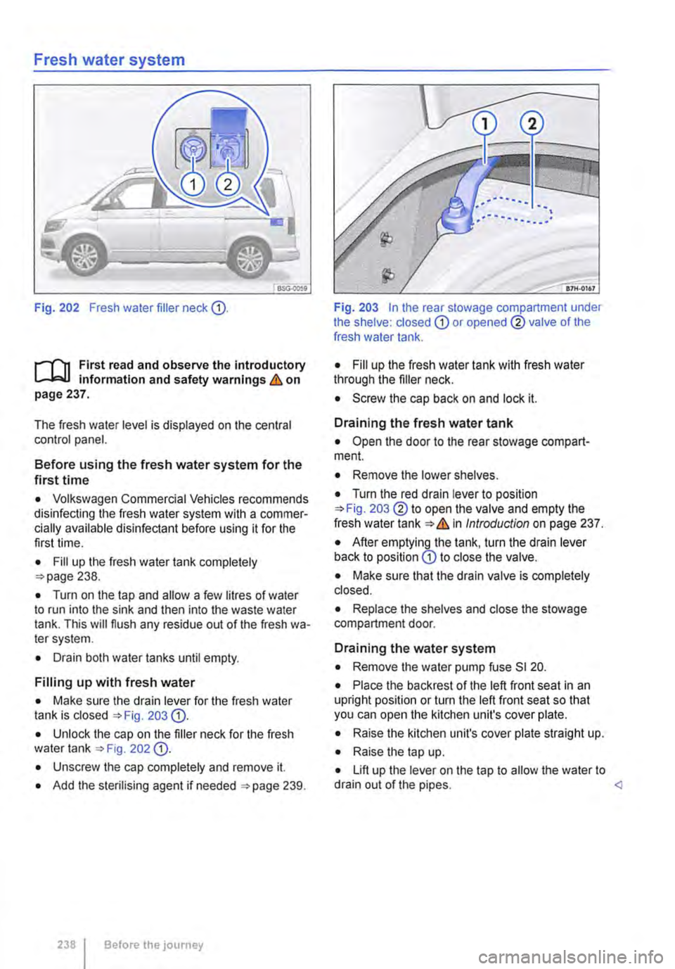
Fig. 202 Fresh water filler neck CD.
l"'""'('n First read and observe the introductory L-J.:.I.I Information and safety warnings & on page 237.
The fresh water level is displayed on the central control panel.
Before using the fresh water system for the first time
• Volkswagen Commercial Vehicles recommends disinfecting the fresh water system with a commer-cially available disinfectant before using it for the first time.
• Fill up the fresh water tank completely =>page 238.
• Turn on the tap and allow a few litres of water to run into the sink and then into the waste water tank. This will flush any residue out of the fresh wa-ter system.
• Drain both water tanks until empty.
Filling up with fresh water
• Make sure the drain lever for the fresh water tank is closed =>Fig. 203 CD.
• Unlock the cap on the filler neck for the fresh water tank =>Fig 202 CD.
• Unscrew the cap completely and remove it.
• Add the sterilising agent if needed =>page 239.
238 I Before the journey
Fig. 203 In the rear stowage compartment under the shelve: closed CD or opened ® valve of the fresh water tank.
• Fill up the fresh water tank with fresh water through the filler neck.
• Screw the cap back on and lock it.
Draining the fresh water tank
• Open the door to the rear stowage compart-ment.
• Remove the lower shelves.
• Turn the red drain lever to position =>Fig. 203 ®to open the valve and empty the fresh water tank=>& In Introduction on page 237.
• After emptying the tank, turn the drain lever back to position CD to close the valve.
• Make sure that the drain valve is completely closed.
• Replace the shelves and close the stowage compartment door.
Draining the water system
• Remove the water pump fuse SI 20.
• Place the back rest of the left front seat in an upright position or turn the left front seat so that you can open the kitchen unit's cover plate.
• Raise the kitchen unit's cover plate straight up.
• Raise the tap up.
• Lift up the lever on the tap to allow the water to drain out of the pipes. <