sensor VOLVO 960 1982 Service Owner's Manual
[x] Cancel search | Manufacturer: VOLVO, Model Year: 1982, Model line: 960, Model: VOLVO 960 1982Pages: 168, PDF Size: 54.28 MB
Page 103 of 168
(
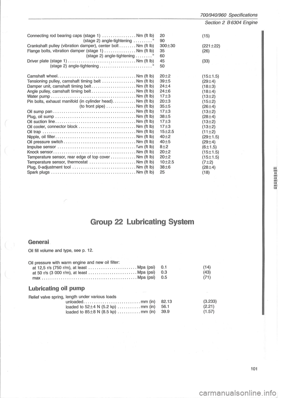
Connecting rod bearing caps (stage 1) ................ Nm (ft Ib)
(stage 2) angle-tightening ......... 0
Crankshaft pulley (vibration damper), center bolt ........ Nm (ft Ib)
Flange bolts, vibration damper (stage 1) ............... Nm (ft Ib)
(stage 2) angle-tightening ........ 0
Driver plate (stage 1) ......................... ....... Nm (ft Ib)
(stage 2) angle-tightening ......................... 0
Camshaft wheel. .................................... Nm (ft Ib)
Tensi oning pulley, camshaft timing belt ................ Nm (ft Ib)
Damper unit, camshaft timing belt ..................... Nm (ft Ib)
Angle pulley, camshaft timing belt ..................... Nm (ft Ib)
Water pump ........................................ Nm (ft Ib)
Pin bolts, exhaust manifold (in cylinder head) ........... Nm (ft Ib)
(to front pipe) .............. Nm (ft Ib)
Oil sump pan ....................................... Nm (ft Ib)
Plug, oil sump ...................................... Nm (ft Ib)
Oil suction line ...................................... Nm (ft Ib)
Oil cooler, connector block ........................... Nm (ft Ib)
Oil trap ............................................ Nm (ft Ib)
Nipple, oil·filter ...................................... Nm (ft Ib)
Oil pressure switch .................................. Nrn (ft Ib)
Impulse sensor ..................................... ~~m (ft Ib)
Knock sensor ....................................... Nm (ft Ib)
Temperature sensor, rear edge of top cover ............ Nm (ft Ib)
Temperature sensor, thermostat ............... ....... Nm (ft Ib)
Plug, O-adjustment tool .............................. Nm (ft Ib)
Spark plugs ... ..................................... Nm (ft Ib)
20
90
300±30
35
60 45
50
20±2
39±5
24±4
24±6
17±3
20±3
35±5
17±3
38±5
17±3
17±3
15±2.5
40±2
40±5
8±2
20±2
20±2
10±2.5
38±6
25
Group 22 Lubricating System
Genera l
Oil fill volume and type, see p. 12.
Oil pressure with warm engine and new oil filter :
at 12,5 rls (750 rim), at least ....... ................ Mpa (psi) 0.1
at
50 rls (3 000 rim), at least ....................... Mpa (psi) 0.3
max
...................... ....................... Mpa (psi) 0.5
Lubricat ing oil pump
Relief valve spring, length under various loads
unloaded
.................... ....... mm (in)
loaded to 52±4 N (5.2 kp) ....... .... mm (in)
loaded to 85±8 N (8.5 kp) ........... mm (in)
82.13
56.1
39.9
70019401960 Specifications
Section 2 B 6304 Engine
(15)
(221 ±22)
(26)
(33)
(15±1.5)
(29±4)
(18±3)
(18±4)
(13±2)
(15±2)
(26±4)
(13±2)
(28±4)
(13±2)
(13±2)
(11 ±2)
(29±1.5)
(29±4)
(6±1.5)
(15±1.5)
(15±1.5)
(7±2)
(28±4)
(18)
(14)
(43)
(71 )
(3.233) (2.21)
(1.57)
101
I ..... ' '.','
"' ,III III ill u,1
Page 105 of 168
150426
(
1456BB
70019401960 Specifications
Section 2 B 6304 Engine
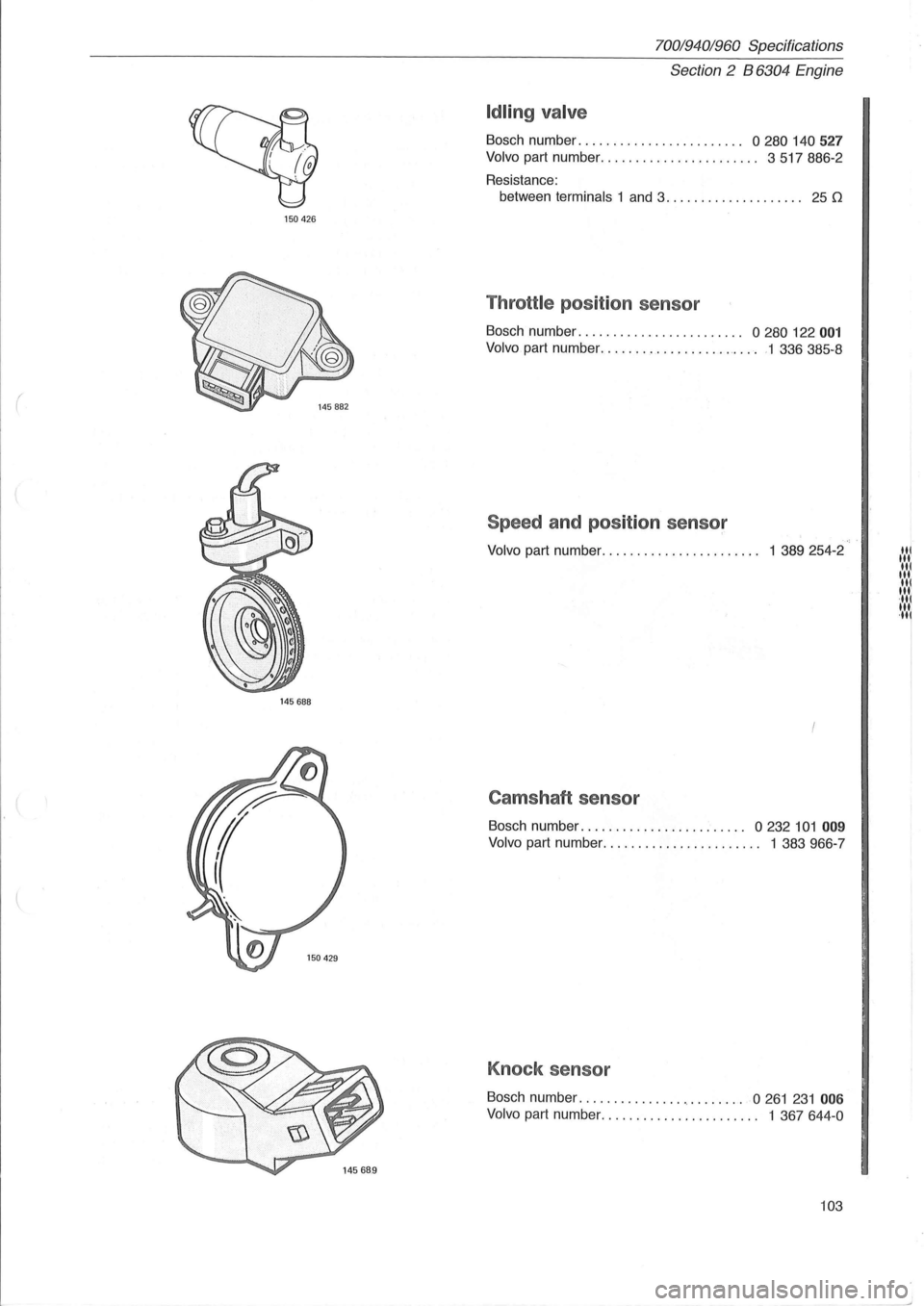
Idling valve
Bosch number. . . . . . . . . . . . . . . . . . . . . . . . 0 280 140 527
Volvo part number ....................... 3517886-2
Resistance:
between
terminals 1 and 3. . . . . . . . . . . . . . . . . . .. 25 D
Throttle position sensor
Bosch number . . . . . . . . . . . . . . . . . . . . . . .. 0 280 122 001
Volvo part number ............... ......... 1 336385-8
Speed and position sensor
Volvo part number. . . . . . . . . . . . . . . . . . . . . .. 1 389 254-2 .... ,1
,'.'.I ,',', ·111
Camshaft sensor
Bosch number. . . . . . . . . . . . . . . . . . . . . . .. 0 232 101 009
Volvo part number ....................... 1 383966-7
Knock sensor
Bosch number. . . . . . . . . . . . . . . . . . . . . . . . 0 261 231 006
Volvo part number. . . . . . . . . . . . . . . . . . . . . .. 1 367 644 -0
103
' .... 1
Page 106 of 168
70019401960 Specifications
Section
2 B 6304 Engine
I
150425
o 580 464 ...
145791
145792
Sil
104
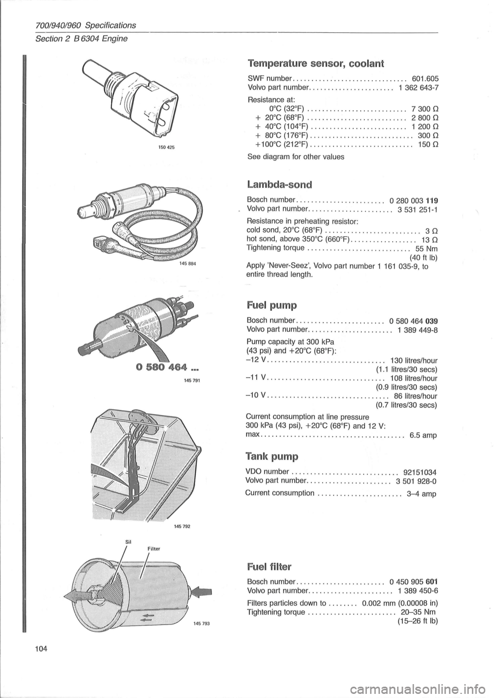
Temperature sensor, coolant
SWF number. . . . . . . . . . . . . . . . . . . . . . . . . . . . . .. 601.605
Volvo part number ....................... 1 362643-7
Resistance
at:
O°C (32°F) . . . . . . . . . . . . . . . . . . . . . . . . . .. 7 300 0
+ 20°C (68°F) . . . . . . . . . . . . . . . . . . . . . . . . . .. 2 800 0
+ 40°C (104°F) . . . .. . . .. . .. . .. . . . . . . . . . .. 1 200 0
+ 80°C (176°F) . . . . . . . . . . . . . . . . . . . .. . . . . . .. 300 0
+100°C (212°F)
............................ 1500
See diagram for other values
Lambda-sond
Bosch number. . . . . . . . . . . . . . . . . . . . . . .. 0 280 003 119
Volvo part number ....................... 3531 251-1
Resistance
in preheating resistor:
cold sand, 20°C (68°F) . . . . . . . . . . . . . . . . . . . . . . . . .. 3 0
hot sand, above 350°C (660°F). . . . . . . . . . . . . . . . .. 13 0
Tightening torque . . . . . . . . . . . . . . . . . . . . . . . . . . .. 55 Nm
(40 ft Ib) Apply 'Never-Seez', Volvo part number 1 161 035-9, to
entire thread
length.
Fuel pump
Bosch number. . . . . . . . . . . . . . . . . . . . . . .. 0 580 464 039
Volvo part number. . . . . . . . . . . . . . . . . . . . . .. 1 389449-8
Pump capacity at 300 kPa
(43 psi) and +20°C (68°F):
-12 V . . . . . . . . . . . . . . . . . . . . . . . . . . . . . . .. 130 lit res/hour
(1.1 litres/30 secs)
-11 V. . . . . . . . . . . . . . . . . . . . . . . . . . . . . . .. 108 litres/hour
(0.9 Iitres/30
secs)
-10 V. . . . . . . . . . . . . . . . . . . . . . . . . . . . . . . .. 86 litres/hour
(0.7 litres/30
secs)
Current consumption
at line pressure
300 kPa (43 psi), +20°C (68°F) and 12 V:
max ................................ ....... 6.5 amp
Tank pump
VDO number. . . . . . . . . . . . . . . . . . . . . . . . . . . .. 92151034
Volvo
part number ....................... 3501 928-0
Current consumption . . . . . . . . . . . . . . . . . . . . . .. 3-4 amp
Fuel filter
Bosch number. . . . . . . . . . . . . . . . . . . . . . .. a 450 905 601
Volvo part number. . . . . . . . . . . . . . . . . . . . . .. 1 389 450-6
Filters particles
down to . . . . . . .. 0.002 mm (0.00008 in)
Tightening torque . . . . . . . . . . . . . . . . . . . . . .
.. 20-35 Nm
(15-26 ft Ib)
Page 116 of 168
70019401960 Specifications
Section 2 024, 024 T, 024 TIC Engines
Group 22 Lubricating system
General
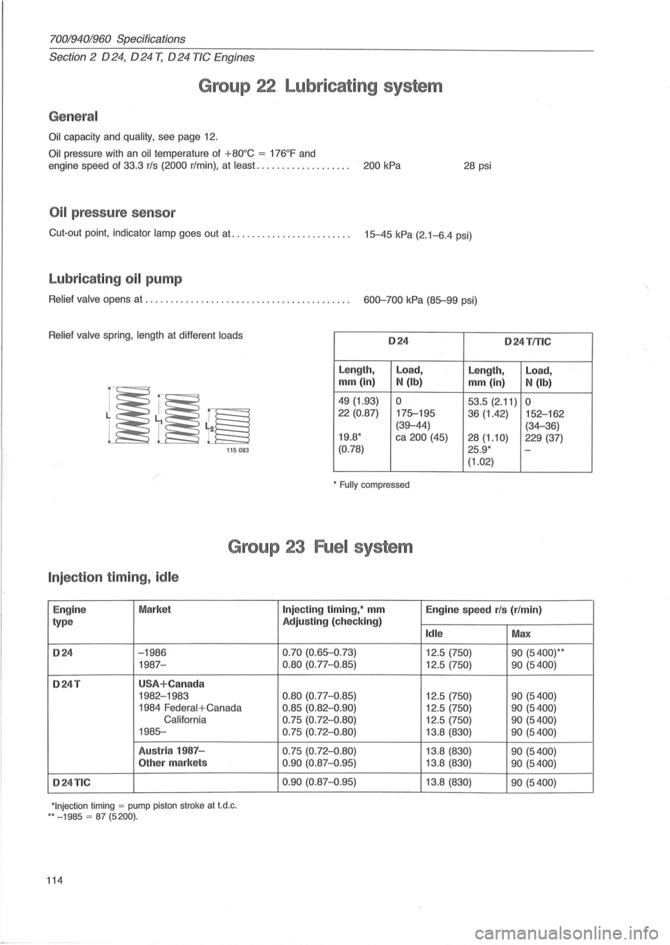
Oil capacity and quality, see page 12.
Oil pressure with an oil temperature of +80°C = 176°F and
engine speed of 33.3 rls (2000 r/min) , at least. . . . . . . . . . . . . . . . . . . 200 kPa 28 psi
Oil pressure sensor
Cut-out point, indicator lamp goes out at. ...................... . 15-45 kPa (2.1-6.4 psi)
Lubricating oil pump ,
Relief valve opens at ........................................ . 600-700 kPa (85-99 psi)
Relief valve spring, length at different loads 024 o 24TfTlC
Length, Load,
Length, Load,
mm (in) N (Ib) mm (in) N (Ib)
49 (1.93) 0 53.5 (2.11) 0 22 (0.87)
175-195
36 (1.42) 152-162
(39-44) (34-36)
19.8 * ca 200 (45)
28(1.10) 229 (37)
115 083 (0.78) 25.9 * -
(1.02)
* Fully compressed
Group 23 Fuel system
Injection timing, idle
Engin e Market
type
024 -1986
1987-
024T USA+Can ada
1982-1983
1984
Federal + Canada
California
1985-
Austr ia 1987 -
Other markets
024TIC
*Injection timing = pump piston stroke at t.d .c . ** - 1985 = 87 (5200).
114
Injecting timing, * mm
Engine speed rls (r/min)
Adjusting (check ing)
Idle Max
0.70 (0.65-0 .73)
12.5 (750) 90 (5400)* *
0.80 (0.77-0.85) 12.5 (750) 90 (5400)
0.80
(0.77-0 .85) 12.5 (750) 90 (5400)
0.85 (0.82-0 .90) 12.5 (750) 90 (5400)
0.75 (0.72- 0 .80) 12.5 (750) 90 (5400)
0.75 (0.72-0 .80) 13.8 (830) 90 (5400)
0.75 (0.72-0.80) 13.8 (830) 90 (5400)
0 .90
(0.87-0 .95) 13.8 (830) 90 (5400)
0.90
(0.87-0.95) 13. 8 (830) 90 (5400)
Page 118 of 168
70019401960 Specifications
Section
2 024, 024 T, 024 TIC Engines
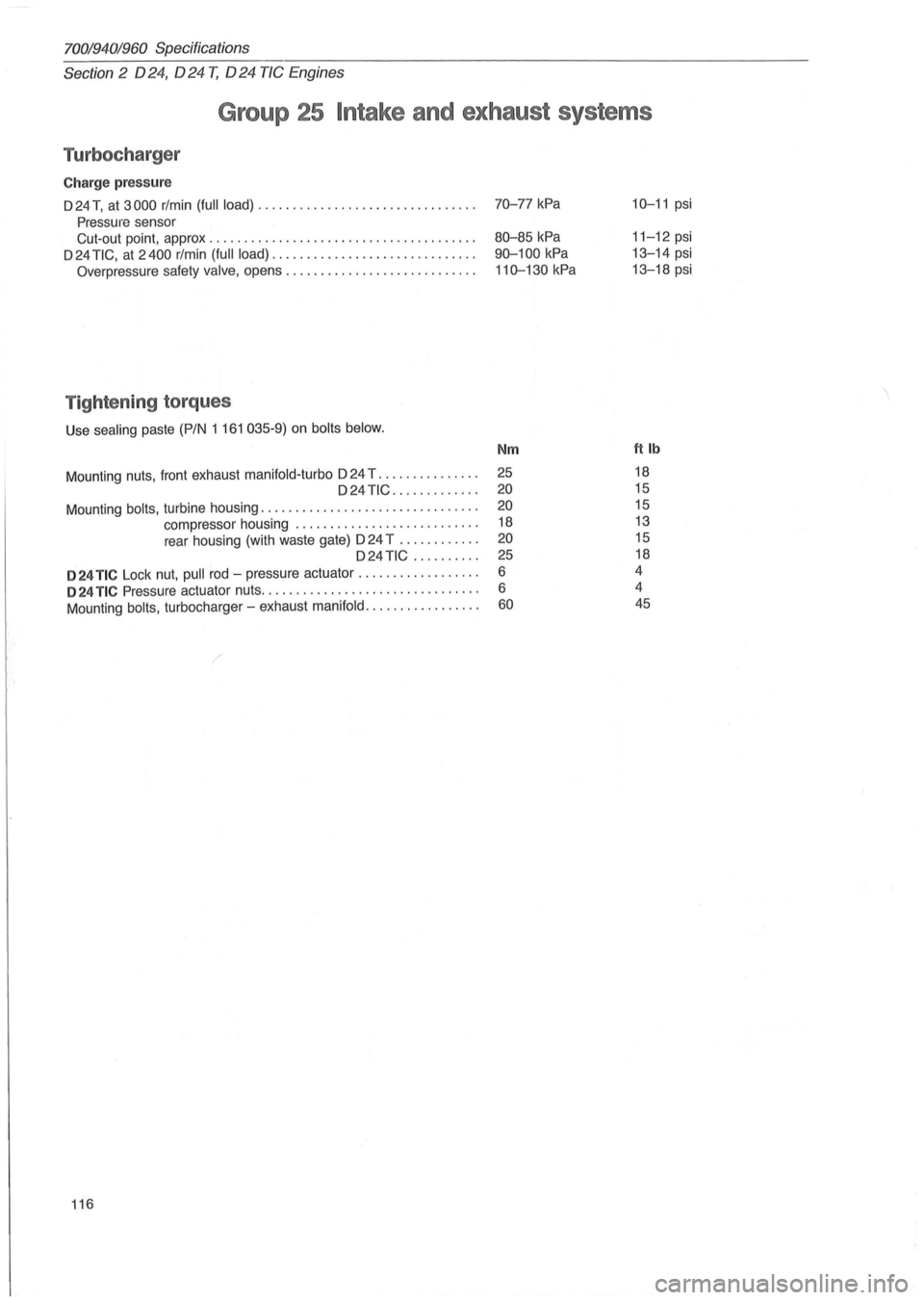
Group 25 Intake and exhaust systems
Turbocharger
Charge pressure
D 24 T, at 3000 rlmin (full load) ............................... .
Pressure sensor
Cut-out point, approx
.................................... .. .
D 24
TIC, at 2400 rlmin (full load) ............................. .
Overpressure safety valve, opens ........................... .
Tightening torques
Use sealing paste (PIN 1 161 035-9) on bolts below.
Mount ing nuts, front exhaust manifold-turbo D 24 T .............. . D24TIC ............ .
Mounting
bolts, turbine housing ............................... .
compressor housing
..................... ..... .
rear housing (with waste gate)
024 T ........... .
D24 TiC ......... .
024 TIC Lock nut, pull rod -pressure actuator ................. .
024 TIC Pressure actuator nuts ............................... .
Mounting
bolts, turbocharger -exhaust manifold ................ .
116
70-77 kPa
80-85 kPa
90-100
kPa
110-130 kPa
Nm
25
20
20
18
20
25
6
6
60
10-11 psi
11-12 psi
13-14 psi
13-18 psi
ftlb
18
15
15
13
15
18
4
4 45
Page 130 of 168
7001940;'960 Specifications
Section 3 Electrical System
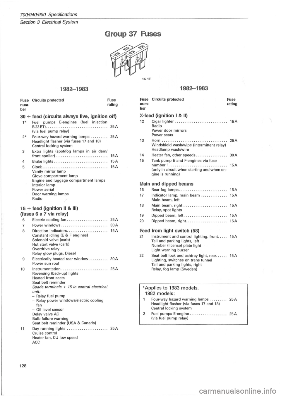
Group 37 Fuses
1982-1983
Fu se Circuits protected
num -
ber Fuse
rating
30 + feed (c ir cu its alw ays live, ig nition off)
1 * Fuel pumps E-engines (fuel injection
B23ET) ........................... ...... 25A (via fuel pump relay)
2* Four-way hazard warning lamps ........ . 25A Headlight flasher (via fuses 17 and 18) Central locking system
3 Extra
lights (spot/fog lamps in air dam/
4
5
front spoiler) ............................ 15A
Brake lights ............. ................ 15A
Clock .......................... ......... 15A Vanity mirror lamp
Glove compartment lamp Engine and luggage compartment lamps
Interior lamp
Power aerial Door warning lamps
Radio
15 + feed (ignition II & III)
(fu ses 6 a 7 via relay)
6 Electric cooling fan ...................... 25A
7 Power windows .................. ....... 30A
8 Direction indicators ...................... 15A Constant idling (E & F engines) Solenoid valve (carb)
Hot start valve (carb)
Overdrive relay
Relay glow plugs , Diesel
9 Electrically heated rear window. . . . . . . . .. 30 A
Power sun roof
10 Instrumentation ...................... , .. 25A Reversing (back-up) lights Heated front seats
Seat belt reminder Spade terminals + 15 in central electrical
unit:
-Relay fuel pump -Relay power windows/electric cooling
fan
-Oil level sensor Delay valve AC Bulb failure warning
Seat belt reminder (USA & Canada)
11 Day running lights ...................... 25A Cruise control
128
Heater fan, CU low speed
ACC
1982-1983
Fuse Circuits protected
num -
ber
X-feed (ign ition I & II)
Fuse rating
12 Cigar lighter ... ......................... 15A Radio
Power door mirrors
Power seats
13 Horn ................................ ... 25A Windshield wash/wipe (intermittent relay)
Headlamp wash/wire
14 Heater fan, other speeds. . . . . . . . . . . . . . . .. 30 A
15 Tank pump E and F-engines via fuse number 1 .............................. . (only in circuit when starting and when engine is running)
Ma in and dipped beams
16 Rear fog lamps ......... .................
17 Indicator lamp, main beam .............. Main beam, left
18 Main beam, right. ....................... Relay, spot lights
19 Dipped beam, left .......................
20 Dipped beam, right ......................
Feed from light switch (58 )
15A
15A
15A
15A
15A
15A
21 Instrument and control lighting, front ..... 15A Tail and parking lights, left Number (license) plate light Light warning buzzer
22 Seat belt lock and ashtray light, rear ...... 15A Lighting, switches on trans tunnel
Tail and parking lights, right Relay, fog lamp (Sweden)
* Applies to 1983 models.
1982 models:
Four-way hazard warning lamps ......... 25A Headlight flasher (via fuses 17 and 18) Central locking system
2
Fuel pumps E-engine .................... 25A (via fuel pump relay)
Page 131 of 168
(
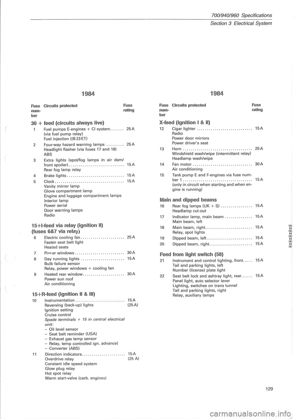
1984
Fuse Circuits protected Fuse
num-rating
ber
30 + feed (circuit s alw ays live)
Fuel pumps E-engines + CI system ....... (via fuel pump relay)
Fuel i njection ((B 23 ET)
2 Four-way
hazard
warning lamps ......... Headlight flasher (via fuses 17 and 18)
ABS
3 Extra lights (spot/fog lamps in
air dam/ front spoiler) . ................ ... .. ......
Rear fog lamp relay
4 Brake lights .....
.. .............•........
5 C lock ....... ............. ............. ..
Vanity mirror lamp Glove compartment lamp Engine and luggage compartment lamps
Interior lamp Power aerial Door warning lamps
Radio
15+I-feed via relay (ignition II)
(fuses 6&7 via relay)
6 Electric cooling fan ................ ...... Fasten seat belt light Heated seats
7
p()\J\; er windows ........... . •.... ........
8 Day
running
lights ..... .......... ....... Bulb failure sensor Relay, power windows + cooling fan
9 Heated
rear
window ................. ....
Power sun roof Air conditioning
15+R-feed (ignition II & III)
10 Instrumentation ........................ .
Reversing (back-up) lights Ignition setting Cruise control
Spade terminals + 15 in central electrical
unit: -Oil level sensor
-Seat belt reminder (USA) -Exhaust gas temp sensor
-Relay, temp contro lled ign. advance)
-Converter (ABS)
25A
25A
15A
15A
15A
25A
30A
15A
30A
15A (25A)
11 Direction indicators.. .. .... .. . .... .. ..... 15A Overdrive relay (25 A) Constant idle speed system Glow plug relay Hot spot relay Warm start-valve (carb. engines)
70019401960 Specifications
Section
3 Electrical System
1984
Fuse C ircuit s protected Fuse
num-rating
ber
X-feed (ignition I & II)
12 Cigar lighter ...... ..............•....... 15A
Radio
Power door mirrors Power driver's seat
13 Horn ...... ........... .. ................ 25A
Windsh ield wash/wipe (interm ittent relay)
Headlamp wash/wipe
14 Fan motor .................. ......... ... 30A
Air conditioning
15 Tank pump E and F-engines via fuse num-ber 1 ...... ...................... ....... 15A
(only in circuit when starting and when en-
gine is running)
Main and dipped beams
16 Rear fog lamps (UK + S) ................ 15A
Headlamp cut-out
17 Indicator lamp, main beam .............. 15A
Main beam , left
18 Main beam, right .......•... ............. 15A IN
Relay, spot lights "I
19 Dipped beam, left ...... ................. 15A IIII( II.
20 D ipped beam, right ...........•.......... 15A "I II. II
Feed from light switch (58)
21 Instrument and control lighting, front ..... 15A
Tail and parking lights, left Number (license) plate light
22 Seat belt lock and ashtray light, rear ...... 15A
Panel light, auto selector lever Lighting, switches on trans tunnel Tail and parking lights, right Relay, auxiliary lamps
129
Page 133 of 168
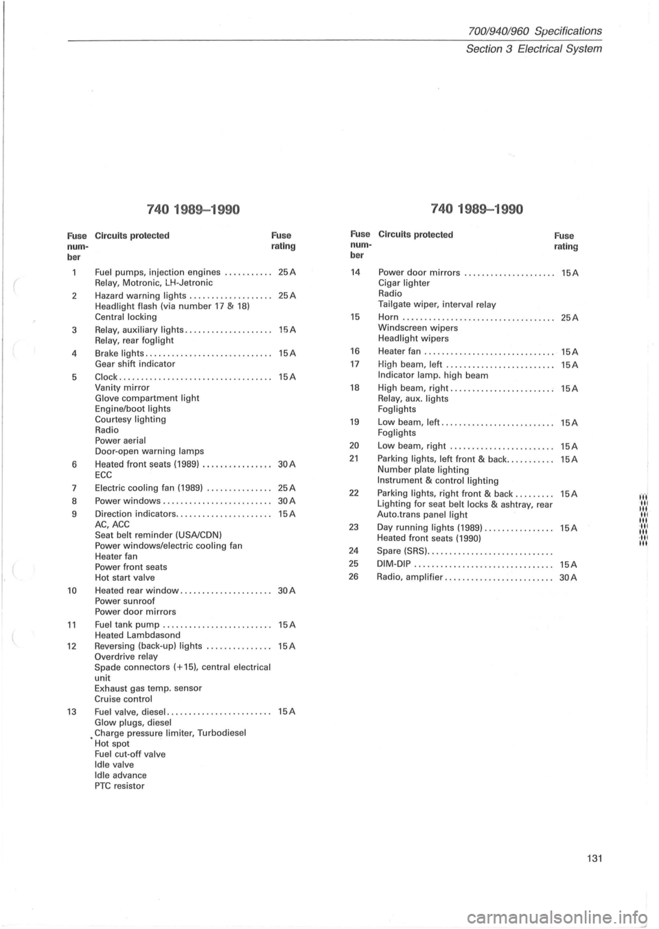
70019401960 Specifications
Section
3 Electrical System
740 1989-1990 740 1989-1990
Fu se Circuit
s prot ect ed F
u se F
u se
Circuit s protected
Fu se
nurn - r
a ting nurn
-
rating
ber b
er
Fuel pumps, injection engines ........... 25A 14 Power door mirrors ..................... 15A
( Relay , Motronic, LH-Jetronic Cigar lighter
2 Hazard
warning lights
................... 25A Radio
Headlight
flash (via number 17 & 18) Tailgate wiper, interval relay
Central locking 15 Horn ..... .......................... .. .. 25A
3 Relay , auxiliary li ghts ............. ....... 15A Windscreen wipers
Relay, rear foglight Headlight wipers
4 Brake
lights
...................... ....... 15A 16 Heater fan .............................. 15A
Gear shift indicator 17 High beam , left ........... .............. 15A
5 Clock ................................ ... 15A Indi cator lamp. high beam
Vanity
mirror 18 High beam, right ...................... .. 15A Glove compartment light Relay, aux . lights
Engine/boot lights
Foglights
Courtesy lighting
19 Low beam, left ................. ......... 15A Radio Foglights Power aerial 20 Low beam, right ................. ....... 15A Door -open warning lamps
6 Heated front seats
(1989) ................ 30A 21 Parking lights, left front & back ........... 15A
ECC Number plate lighting
7 Electric
cooling fan (1989)
............... 25A Instrument & control lighting
22 Parking lights, right front & back ......... 15A fn' 8 Power windows .
................... ..... 30A Lighting for seat belt locks & ashtray, rear III III 9 Direction
indicators ...................... 15A Auto.trans panel light III III AC,ACC 23 Day running lights (1989) ................ 15A '111 Seat belt reminder (USA/CDN) III Heated front seats (1990) ·111 Power windows/electric cooling fan III
Heater fan 24 Spare (SRS) .............................
Power front seats 25 DIM-DiP .. ..............•............... 15A
Hot start valve 26 Radio , amplifier ............... .......... 30A
10 Heated rear window ................. .... 30A Power sunroof
Power door mirrors
11 Fuel tank pump . .. ............. ......... 15A Heated Lambdasond
12 Reversing (back-up) lights ..... .... ...... 15A Overdrive relay
Spade connec tors (+15), central electrical
unit Exhaust gas temp. sensor
Cruise control
13 Fuel valve, diesel ..................... ... 15A Glow plugs, diesel • Charge pressure limiter, Turbodiesel
Hot spot
Fuel cut-off valve
Idle valve Idle advance PTC resistor
131
Page 134 of 168
70019401960 Specifications
Section 3 Electrical System
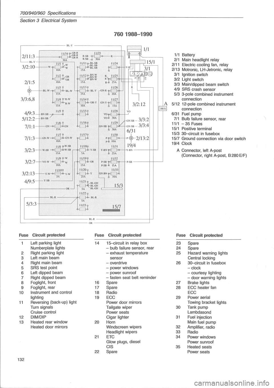
760 1988-19 90
,----------BL-Y ---------,
I 11/3 4 GR-R ~ ~ 1
: 3 -+~---'----'-<>e+-q=-OA-HlCg~:~ ~:~~--l '3M ~ •
. ~
BL- Y II/II 11/2 4
3/2:10
4/9:3
5/12:2
7/1: 1
3/2:3
3/2:
13
4/9:5 5/3:3
Fus e Circuit
protected
Left parking light
Numberplate lights
2 Right
parking light
3 Left
main beam
4 Right
main beam
5
SRS test point
6 Left
dipped beam
7 Right
dipped beam
8
Foglight, front
9
Foglight, rear
10
Instrument and control
lighting
11 Revers ing (back -up) light
Turn signals
Cruise control
12 DIMIDIP
13 Heated rear window
Heated door mirrors
132
BL- R OR
3/2 : 12
GN-5 B -3/3:2
GN-5 B -3/3:4
6/31
pf-2/13:2
19/4
15/7
F u se Circuit
protected
14 1 frcircuit in relay box
-
bulb failure sensor, rear
- exhaust temperature
sensor
- overdrive
- power windows
- power sunroof
- fasten seat
belt reminder
16 Spare
17 Spare
18 Radio
19 ECC
Power door mirrors
Tailgate wiper
Power seats
Cigar
lighter
20 Horn
Windscreen wipers
Headlight wipers
21 ETC
Glow plugs, diesel
CIS
22 Spare
A 100)
1/1 Battery
211 Main headlight relay
2111 Electric cooling fan, relay
2113 Motronic, LH-Jetronic, relay
3/1 Ignition switch
3/2 Light switch
3/3 Mainldipped beam switch
4/9 SRS crash sensor
5/3 3-pole combined instrument
connection
5/12 12 -pole combined instrument
connection
6/31 Fuel pump
7/1 Bulb failure sensor, rear
11/1 -35 Fuses
15/1 Positive terminal
15/3 3G-circuit in fusebox
15/7 Ground connection via door switch
19/4 Clock
A Connector, left A-post
(Connector, right A-post, B 280 ElF)
Fuse
Circuit protected
23 Spare
24 Spare
25 Hazard warning lights
Central locking
26 3G-circuit in fusebox
-
clock
- courtesy lighting
- door warning lights
27 Brake lights
28 ECC heater fan
ECC
29 Power aerial
Towing bracket lights
30 Tank
pump
Lambdasond
31 Fuel injection
Main
fuel pump
32 Amplifier, radio
33 Radio
34
Power windows
Power sunroof
35 Heated seats
Power seats
Page 135 of 168
(
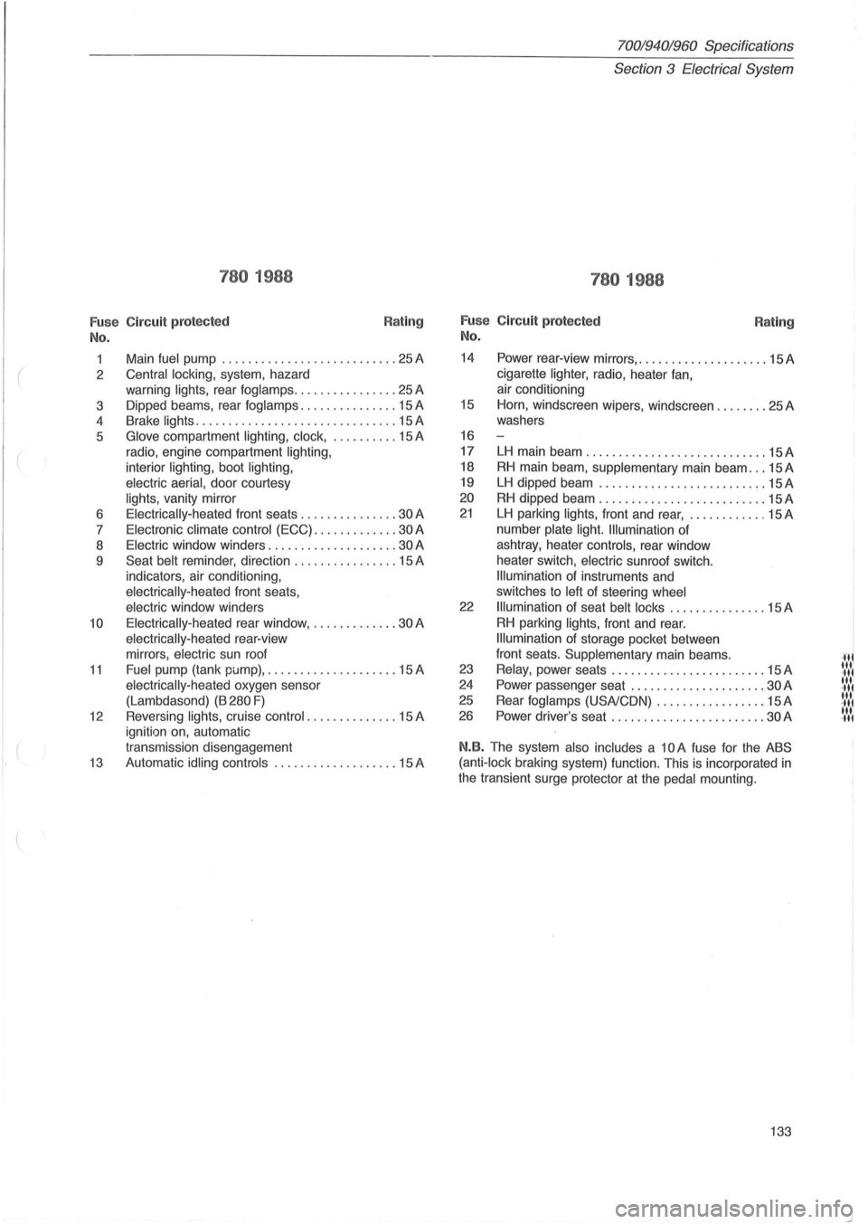
780 1988
Fu se Circuit protected
No.
Rating
1 Main fuel pump ........................... 25 A
2
Central locking, system, hazard
warning
lights, rear fog lamps ................ 25 A
3 Dipped beams, rear
foglamps ............... 15 A
4 Brake
lights .................. ............. 15 A
5
Glove compartment lighting, clock, .......... 15 A
radio, engine compartment
lighting,
interior lighting, boot lighting,
electric aerial,
door courtesy
lights, vanity mirror
6
Electrically-heated front seats ............... 30 A
7
Electronic climate control (ECC) ............. 30 A
8
Electric window winders .................... 30 A
9
Seat belt reminder , direction ................ 15 A
indicators, air conditioning ,
electrically-heated front seats,
electric window winders
10 Electrically-heated rear window, ............. 30 A
electrically -heated rear-view
mirrors,
electric sun roof
11 Fuel pump (tank pi.Jmp), .................... 15 A
electrically-heated oxygen sensor
(Lambdasond)
(B 280 F)
12 Reversing lights, cruise control .. ............ 15 A
ignition on, automatic
transmission disengagement
13 Automatic idling controls ................... 15 A
70019401960 Specifications
Section
3 Electrical System
780 1988
Fu se Circuit protected
No. Rating
14 Power rear-view mirrors, .................... 15 A
cigarette
lighter, radio, heater fan,
air conditioning
15 Horn, windscreen wipers, windscreen ........ 25A
washers
16
17
LH main beam ............................ 15A
18 RH main beam , supplementary main beam ... 15 A
19 LH dipped beam ............. ............. 15A
20 RH dipped beam .......................... 15 A
21 LH parking lights, front and rear, ............ 15 A
number
plate light. Illumination of
ashtray, heater
controls, rear window
heater switch,
electric sunroof switch.
Illumination of instruments and
switches to
left of steering wheel
22 Illumination of seat belt locks ............... 15 A
RH parking lights, front and rear.
Illumination of storage pocket between
front seats.
Supplementary main beams .
23 Relay, power seats ................ .... .... 15 A
24 Power passenger seat .................. ... 30 A
25 Rear fog lamps (USA/CON) ................. 15 A
26 Power driver's seat ................... .. .. . 30 A
N.B. The system also includes a 10 A fuse for the ABS
(anti-lock
braking system) function. This is incorporated in
the transient surge protector at the pedal mounting.
133
·,f' "'I .", '" .",
'" .",
'" .",