sensor VOLVO 960 1982 Service Owner's Guide
[x] Cancel search | Manufacturer: VOLVO, Model Year: 1982, Model line: 960, Model: VOLVO 960 1982Pages: 168, PDF Size: 54.28 MB
Page 138 of 168
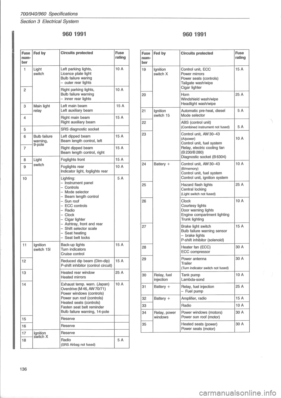
70019401960 Specifications
Section
3 E lectrical System
I
960 1991
Fuse Fed by C ircuit s protecte d Fuse
960 1991
Fuse Fed by Circuit s protected Fuse nurn-rating nurn- r
ating
b er
ber
1 Light
Left
parking lights, 10 A
19 Ignition Control unit, ECC 15
A
switch Licence plate
light switch X Power
mirrors Bulb failure waring
Power seats (controls)
-outer rear lights
Tailgate wash/wipe t---2 Right
parking lights, 10 A Cigar lighter I----Bulb failure
warning 20 Horn 25
A -inner rear lights
Windshield wash/wipe
3 Main
light Left
main beam 15
A Headlight wash /wipe
relay Left auxiliary beam 21 Ignition Automatic pre-heat, diesel 5A r---4 Right
main beam 15 A switch
15 Mode selector I----Right auxiliary beam
22 ABS (control unit)
5
SRS diagnostic socket (Combined instrument not fused) 5A I----
6 Bulb failure Left dipped beam 15
A
warning , Beam length
control, left t---9-pole 7 Right
dipped beam 15
A 23
Control unit, AW 30-43 (A/power) 10 A
Control unit, fuel system Relay,
electric cooling fan
Beam length control, right (B
230/B 280)
8 Light
Foglights front
15 A Diagnostic
socket (B 6304)
r---switch
9 Foglights rear 10 A Indicator light, foglights rear -
24 Battery + Control unit, AW 30-43 10 A
(B/m emory) Control unit , fuel system
10 Lighting : 5A -Instrument panel
- Controls
-
Mode selector
-Beam length control Control
unit
, ignition system t---25 Hazard flash lights 25 A Central locking (Light switch not fused) I-----(Sun roof
26 Clock 10 A
-
ECC controls Courtesy lights
-Radio Door
warning lights
- Clock Engine compartment lighting
-Cigar lighter Trunk lighting
-Ashtray, front and rear -Shift selector scale
- Seat heating -Seat belt locks
I----27 Brake light switch 15
A Bulb failure warning sensor -brake lights P-shift inhibitor (solenoid)
11 Ignition Back-up lights 15 A
switch
151 Turn indicators
Cruise control
I----28 Heater
fan (ECC) 30 A
ECC compr essor t---t---12 Reduced
dip beam (Dim-dip) 15 A
P-shift inhibitor (control circuit) r---
29 Power antenna 30 A
Trailer (Turn indicator switch not fused)
13 Heated
rear window 25 A
Heated mirrors
t---
30 Relay,
fuel Tank pump 10 A
injection Lambda-sond
14 Exhaust
temp. warn. (Japan)
10 A
Overdrive
(M 46, AW 70/71)
Power windows (controls)
31 Battery + Relay, fuel injection 25
A -Fuel pump
Power sun roof
(controls) 32 Battery + Amplifier, radio 15
A
Heated seats (controls) Fasten seat belt reminder
I----33 Radio 10 A
Bulb
failure warning, 14-pole t---15 Reserve t---16 Reserve 3
4
Relay , power Power
windows (motors) 30 A
windows Power
sun roof (motor)
t---35 Heated
seats (power) 30 A
Power seats (motor)
17
Ignition Reserve t---switch X
18 Radio 5A (SRS
Airbag not fused)
136
Page 139 of 168
(
70019401960 Specifications
Section 3 Electrical System
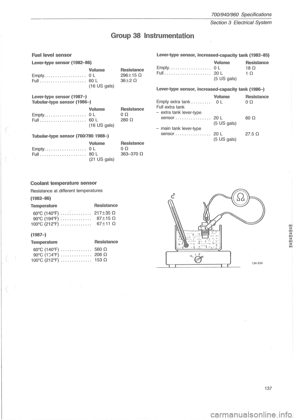
Group 38 Instrumentat ion
Fuel leve l sensor
Lever-type sensor (1982-86)
Volume
Empty ................... 0 L
Full ................. .... 60 L
(16 US gals)
Lever-type sensor (1987-)
Tubular-type se nsor (1986-)
Volume
Empty ............. , ..... 0 L
Full ..................... 60 L
(16 US gals)
Tubular-type
se nso r (7601780 1988-)
Volum e
Empty ................... 0 L
Full ..................... 80 L
(21 US gals)
Coo lant temperature sensor
Resistance at different temperatures
(1982-86)
Temperature
600e (140°F) ............ ..
900e (194°F) ............. .
1000e (212°F) ............. .
(1987 -)
Temperature
600e (140 °F) ............. .
900e (VWF) ............ . .
100De (212 °F) ............. .
Res istance
217±350
87±150
67±11 0
Resistance
5600
2060
1530
Resistance
296±1S 0
36±20
Resistance
00
2800
Resistance
00
363-3700
Lever-type sensor, incre ased-capac ity tank (1982-85)
Volum e
Empty ................ ... 0 L
Full .............. ....... 20 L
(S US gals)
Resistance
180
1 0
Lever-type sensor, increased-capac ity tank (1986-)
Volume
Empty extra tank . . . . . . . .. 0 L
Full extra tank
- extra tank
lever-type
sensor ................ 20 L
(S US gals)
-main tank lever-type
sensor . . . . . . . . . . . . . . .. 20 L
(S US gals)
Res istance
00
600
27 .S 0
137
fl'l 1 til 1 It I .1 til .1 til
Page 150 of 168
700/940/960 Specifications
Section
4 Powe r Transmission
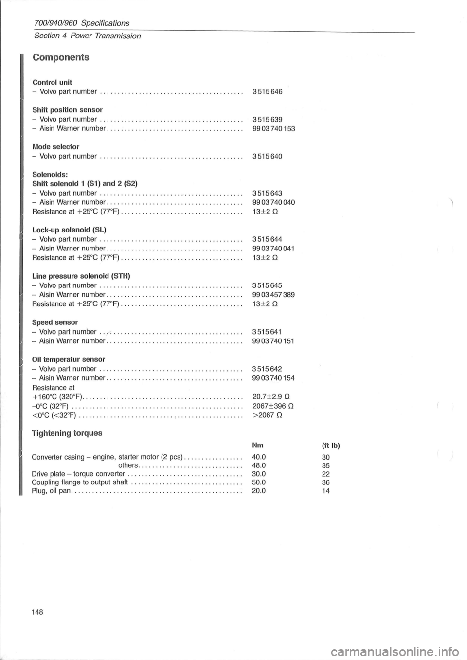
Components
Contro l unit
-Volvo part number . . . . . . . . . . . . . . . . . . . . . . . . . . . . . . . . . . . . . . . . . 3515646
ShiH position sensor
-Volvo part number. . . . . . . . . . . . . . . . . . . . . . . . . . . . . . . . . . . . . . . . . 3515639
- Aisin Warner number. . . . . . . . . . . . . . . . . . . . . . . . . . . . . . . . . . . . . . .
9903740153
Mode se lector
-Volvo part number . . . . . . . . . . . . . . . . . . . . . . . . . . . . . . . . . . . . . . . . . 3515640
Solenoids :
ShiH solenoid
1 (51) and 2 (52)
-Volvo part number. . . . . . . . . . . . . . . . . . . . . . . . . . . . . . . . . . . . . . . . . 3515643
- Aisin Warner number. . . . . . . . . . . . . . . . . . . . . . . . . . . . . . . . . . . . . . .
9903740040
Resistance at +25°C (7rF). . . . . . . . .. ... . . . . . . . . .. . . . . .. . . . . .. 13±20
Lock-up so lenoid (SL)
-Volvo part number. . . . . . . . . . . . . . . . . . . . . . . . . . . . . . . . . . . . . . . . . 3515644
- Aisin Warner number. . . . . . . . . . . . . . . . . . . . . . . . . . . . . . . . . . . . . . .
9903740041
Resistance at +25°C (7rF) ............. " . . . . . . . . . . . . .. . . .. . . 13±20
Line pressur e sole noid (5TH)
-Volvo part number. . . . . . . . . . . . . . . . . . . . . . . . . . . . . . . . . . . . . . . . . 3515645
- Aisin Warner number. . . . . . . . . . . . . . . . . . . . . . . . . . . . . . . . . . . . . . .
9903457389
Resistance at +25°C (7rF). . . . . . . . . . . . . ... . .. ..... . . . . ... .. . . 13±20
Speed sensor
-Volvo part number ... ..-: . . . . . . . . . . . . . . . . . . . . . . . . . . . . . . . . . . . . . 3515641
- Aisin Warner number. . . . . . . . . . . . . . . . . . . . . . . . . . . . . . . . . . . . . . .
9903740151
Oil te mp eratur senso r
-Volvo part number. . . . . . . . . . . . . . . . . . . . . . . . . . . . . . . . . . . . . . . . . 3515642
- Aisin Warner number. . . . . . . . . . . . . . . . . . . . . . . . . . . . . . . . . . . . . . .
9903740154
Resistance at
+160°C (320°F)......... .. .... . ......... ....... .............. 20.7±2.90
-O°C (32°F) .. . . . . . . .. . . . . . . . . . . . . . . .. . . . . . . .. . . .. . . . .. . . . . . . 2067±396 0
Tightening torques
Nm (ft Ib)
Converter casing -engine, starter motor (2 pcs) ................ . 40.0 30 others .............. ............... . 48.0 35
Drive plate -torque converter ................................ . 30.0 22
Coupling flange to output shaft ............................... . 50.0 36
Plug, oil pan ................................................ . 20.0 14
148
Page 153 of 168
(
70019401960 Specifications
Section
4 Power Transmission
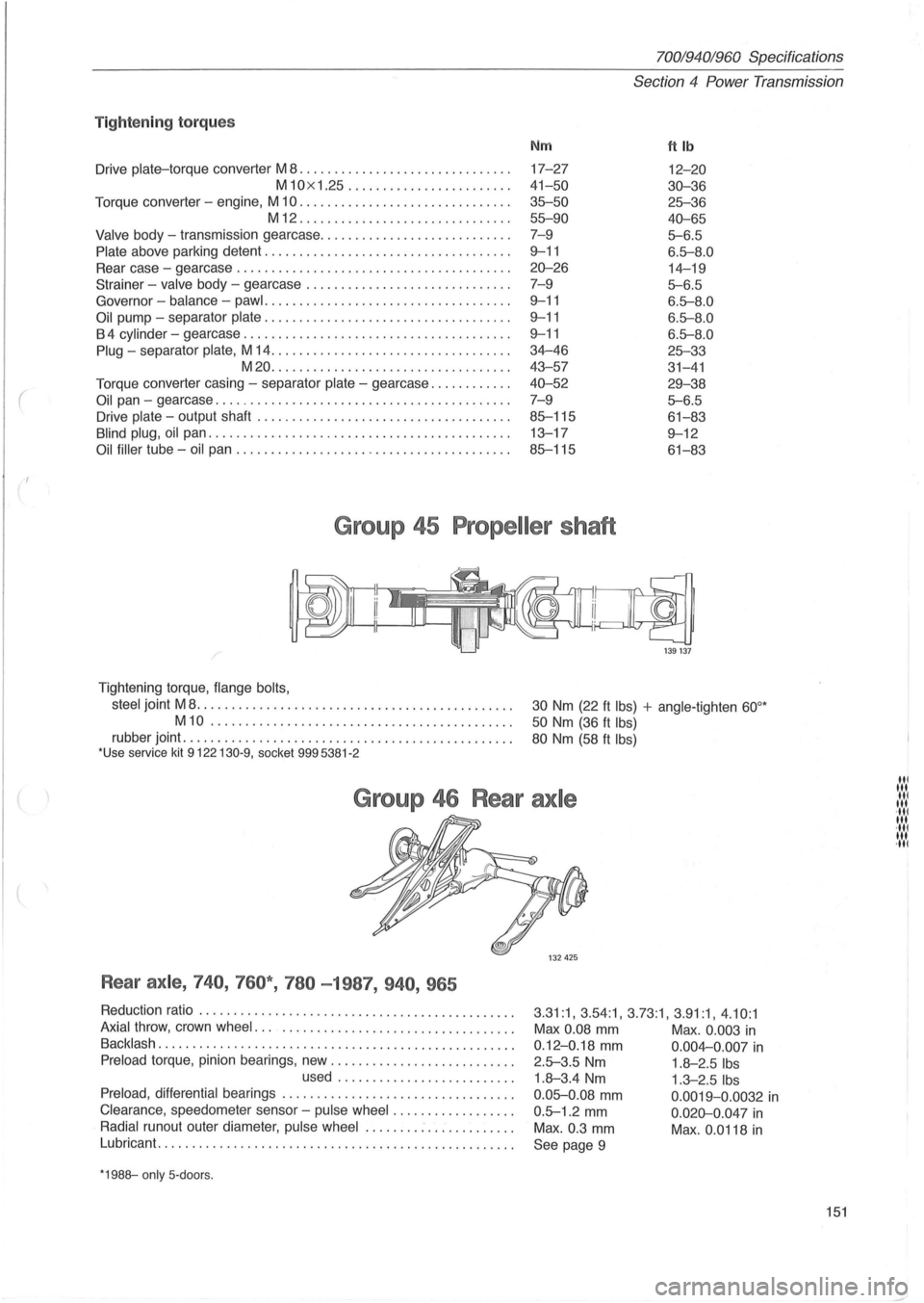
Tig ht enin g to rqu es
Nm ftlb
Drive plate-torque converter M 8 ................ .............. . 17-27 12-20
M10x 1.25 ......... .............. . 41-50 30-36
Torque converter -engine, M 10 .............................. . 35--50 25--36
M12 ........................ ...... . 55--90 40-65
Valve body -transmission gearcase ....................... .... . 7-9 5--6.5
Plate above parking detent ............ ............ ........... . 9--11 6.5--8 .0
Rear case -gearcase .............................. ......... . 20-26 14-19
Strainer - valve body -gearcase ................ ............ . . 7- 9
5--6.5
Governor -balance -pawl .......... ......................... . 9--11 6.5--8.0
Oil pump -separator plate .................. ................ . . 9--11 6.5--8 .0
B 4 cylinder -gearcase ...................................... . 9--11 6.5--8 .0
Plug -separator plate, M 14 .................................. . 34-46 25--33
M20 ....... ................ ...... ..... . 43- 57
31-41
Torque converter casing -separator plate -gearcase ........... . 40-52 29-38
Oil pan -gearcase .......................................... . 7-9 5--6.5
Drive plate -output shaft .................................... . 85--115 61-83
Blind plug, oil pan .................... ................. ...... . 13-17 9--12
Oil filler tube -oil pan ....................................... . 85--115 61-83
Group 45 Propeller shaft
/'
Tightening torque, flange bolts,
steel
joint M 8 ....................... ...... ..............•..
M10 ......................... .. ................ .
rubber joint ...................................... ......... . *Use service kit 9122130-9, socket 9995381 -2
ikd@
1 39 137
30 Nm (22 ft Ibs) + angle-tighten 60°*
50 Nm (36 ft Ibs)
80 Nm (58 ft Ibs)
Group 46 Rear axle
Rear axle , 740 , 760* , 780 -1987, 940 , 965
Reduction ratio ...................................... ....... . 3 .31:1, 3.54:1 , 3.73:1, 3 .91:1, 4 .10 :1 Axial throw, crown wheel ..................................... . Max 0.08 mm Max . 0.003 in Backlash ... ................................................ . 0 .12-0.18 mm 0 .004-0.007 in Preload torque, pinion bearings, new .......................... . 2.5--3.5 Nm 1.8-2.5 Ibs used ...... ... ................ . 1.8-3.4 Nm 1.3-2.5 Ibs
Preload, differential bearings ................................. . 0 .05--0 .08 mm 0.0019-0 .0032 in Clearance , speedometer sensor -pulse wheel .... .. ........... . 0 .5--1.2 mm 0 .020-0.047 in Radial runout outer diameter, pulse wheel ........ : .. : ......... . Max . 0.3 mm Max . 0.0118 in Lubricant ....... . ........................................... .
See page 9
*1988--only 5- doors.
151
III 1 .... 1 III ·111 III ·111 III ·111
Page 154 of 168
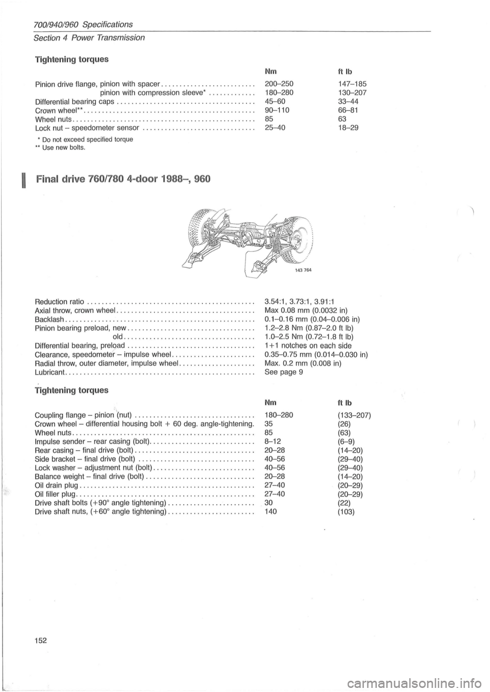
70019401960 Specifications
Section
4 Power Transmission
Tightening torqu es
Pinion drive flange, pinion with spacer .......... ........ ....... .
pinion with compression
sleeve ' ............ .
Differential bearing caps .............................. ...... . .
Crown
wheel " .. ............................ .......... ...... .
Wheel nuts ...... ............................... .. .......... .
Lock nut -speedometer sensor .
............................. .
• Do not exceed specified torque .. Use new bolts.
I Final drive 760 /780 4-door 1988-, 960
Reduction ratio ................................... .......... .
Axial throw , crown wheel ..................................... .
Backlash ............... .................................... .
Pinion bearing
preload , new .................................. .
old ........ .. ..... .................... .
Differential bearing, preload .................................. .
Clearance , speedometer' -impulse wheel ....... ............... .
Radial throw , outer diameter, impulse wheel ....... ............. .
Lubricant.
..... ............................................. .
T ightening torque s
='.. Coupling flange -pinion (nut) ................................ .
Crown
wheel -differential housing bolt + 60 deg . angle-tightening.
Wheel nuts .. ............................. .................. .
Impulse sender -rear casing (bolt) ............................ .
Rear casing -
final drive (bolt) ................................ .
Side bracket -final drive (bolt) ............................... .
Lock washer -adjustment nut
(bolt) ........................... .
Balance weight -final drive (bolt) ............................. .
Oil drain plug ............................................... .
Oil filler plug ................................................ .
Drive shaft
bolts (+900 angle tightening) ....................... .
Drive shaft nuts,
(+600 angle tightening) ............... ........ .
152
Nm ttlb
200-250 147-185
180-280 130-207
45-60 33-44
90-110 66-81
85 63
25-40 18-29
3.54:1, 3.73:1, 3.91:1
Max 0.08 mm (0.0032 in)
0.1-0. 16 mm (0.04--0 .006 in)
1.2-2.8 Nm (0.87 -2.0 ft Ib)
1.0-2.5 Nm (0.72-1 .8 ft Ib)
1 + 1 notches on each side
0.35-0.75 mm (0.014--0.030 in)
Max.
0.2 mm (0. 008 in)
See page 9
Nm
180-280
35
85
8-12
20-28
40-56
40-56
20-28
27-40
27-40
30
140
ftlb
(133-207)
(26)
(63)
(6-9)
(14--20)
(29-40)
(29-40)
(14--20)
(20-29)
(20-29)
(22)
(103)
Page 163 of 168
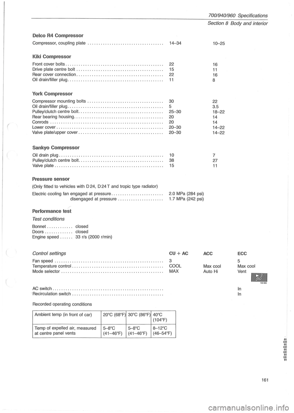
(
Delco R4 Compressor
Compressor, coupling plate ................................... 14-34
Kiki Compressor
Front cover bolts. . . . . . . . . . . . . . . . . . . . . . . . . . . . . . . . . . . . . . . . . . . . . 22
Drive
plate centre bolt . . . . . . . . . . . . . . . . . . . . . . . . . . . . . . . . . . . . . . . . 15
Rear cover connection. . . . . . . . . . . . . . . . . . . . . . . . . . . . . . . . . . . . . . . .
22
Oil drain/filler plug. . . . . . . . . . . . . . . . . . . . . . . . . . . . . . . . . . . . . . . . . . . . 11
York Compressor
Compressor mounting bolts ........................ .......... .
Oil drain/filler plug ........................................... .
Pulley/clutch centre bolt. ..................................... .
Rear bearing housing
.................................. ...... .
Con rods .
.................................................. .
Lower cover
........................................ .. ...... .
Valve plate/upper cover ...................................... .
Sankyo Compressor
30
5
25-30
20
20
20-30
20-30
Oil drain plug. . . . . . . . . . . . . . . . . . . . . . . . . . . . . . . . . . . . . . . . . . . . . . . . 10
Pulley/clutch
centre bolt. . . . . . . . . . . . . . . . . . . . . . . . . . . . . . . . . . . . . . . 38
Valve plate. . . . . . . . . . . . . . . . . . . . . . . . . . . . . . . . . . . . . . . . . . . . . . . . . . 15
Pressure sensor
(Only fitted to vehicles with D 24, D 24 T and tropic type radiator)
70019401960 Specifications
Section 8 Body and interior
10-25
16
11
16
8
22
3.5
18-22
14
14
14-22
14-22
7
27
11
Electric cooling fan engaged at pressure ....................... .
disengaged at pressure
.................... .
2.0 MPa (284 psi)
1 .7 MPa (242 psi)
Performance test
Test conditions
Bonnet . . . . . . . . . . .. closed
Doors . . . . . . . . . . . .. closed
Engine
speed. . . . .. 33 r/s (2000 r/min)
Control settings
Fan speed ........................... ...................... .
Temperature
control . ................................. ....... .
Mode
selector . ............................................. .
AC switch ............. ..................................... .
.
Recirculation switch ......................................... .
Recorded operating conditions
Ambient temp
(in front of car) 20°C (68°F) 30°C (86°F)
40°C
(104 °
F)
Temp of expelled air, measured 5-8°C 5-8°C 8-12°C
CU + AC
3
COOL
MAX
at centre panel vents
(41-46°F) (41-46 °F) (46-54°F)
ACC
Max cool
Auto Hi
ECC
5
Max cool
Vent
-In
In
143985
161
·11 lit ·11 lit ·11 lit ·11 III II