ignition VOLVO S60 2015 Owner´s Manual
[x] Cancel search | Manufacturer: VOLVO, Model Year: 2015, Model line: S60, Model: VOLVO S60 2015Pages: 406, PDF Size: 11.26 MB
Page 5 of 406
Contents
* Option/accessory, for more information, see Introduction.3
03
03 Your driving environment
Instruments and controls.......................... 78
Ignition modes.......................................... 88
Seats......................................................... 90
Steering wheel.......................................... 96
Lighting..................................................... 98
Wipers and washers............................... 106
Windows................................................. 108
Mirrors..................................................... 110
Digial compass*...................................... 113
Power moonroof..................................... 115 HomeLink ®
Wireless Control System*.... 117
Starting the engine.................................. 120
Transmission........................................... 125
Eco Guide* and Power Meter*................ 130
Eco* ........................................................ 132
Start/Stop* ............................................. 135
Brakes..................................................... 139
Parking brake.......................................... 142
04
04 Driver support
Stability system....................................... 148
Road sign information (RSI)* .................. 151
Cruise control.......................................... 153
Adaptive Cruise Control (ACC)*.............. 155
Distance Alert* ....................................... 166
City Safety™ .......................................... 169Pedestrian and Cyclist Detection with
Full Auto Brake*...................................... 175
Driver Alert System* ............................... 185
Park assist*............................................. 194
Rear Park Assist Camera (PAC)* ............ 198
Park Assist Pilot (PAP)* .......................... 202
Blind Spot Information System (BLIS)* .. 206
05
05 Comfort and driving pleasure
Volvo Sensus.......................................... 212
Menus and messages............................. 213
The MY CAR menus............................... 215
Climate system....................................... 221
Trip computer......................................... 230
Active chassis system–Four C*............... 237
Passenger compartment convenience... 238
Page 11 of 406
Introduction
Important information
9
ShiftlockWhen your vehicle is parked, the gear selec- tor is locked in the P (Park) position. To
release the selector from this position, theignition must be in mode II (see page 88) orthe engine must be running. Depress thebrake pedal, press the button on the frontside of the gear selector and move the selec-tor from P (Park).
Anti-lock Brake System (ABS)The ABS system performs a brief self-diag-nostic test when the engine has been startedand driver releases the brake pedal. Anotherautomatic test may be performed when thevehicle first reaches a speed of approximately6 mph (10 km/h). The brake pedal will pulsateseveral times and a sound may be audiblefrom the ABS control module. This is normal.
Fuel filler doorPress the button on the light switch panel(see the illustration on page 294) when thevehicle is at a standstill to unlock the fuel fillerdoor. It will relock when closed and there willbe an audible click.
Points to keep in mind
• Do not export your Volvo to another country before investigating that coun-try's applicable safety and exhaust emis-sion requirements. In some cases it maybe difficult or impossible to comply with these requirements. Modifications to theemission control system(s) may renderyour Volvo not certifiable for legal opera-tion in the U.S., Canada and other coun-tries.
• All information, illustrations and specifica-tions contained in this manual are basedon the latest product information availa-ble at the time of publication. Please notethat some vehicles may be equipped dif-ferently, depending on special legalrequirements. Optional equipment descri-bed in this manual may not be available inall markets.
• Some of the illustrations shown aregeneric and may not depict the exactmodel for which this manual is intended.
• Volvo reserves the right to make modelchanges at any time, or to change speci-fications or design without notice andwithout incurring obligation.
Crash event data
This vehicle is equipped with an event data recorder (EDR). The main purpose of an EDRis to record, in certain crash or near crash-likesituations, such as an air bag deployment orhitting a road obstacle, data that will assist inunderstanding how a vehicle's systems per-formed. The EDR is designed to record datarelated to vehicle dynamics and safety sys- tems for a short period of time, typically 30seconds or less. The EDR in this vehicle isdesigned to record such data as:
• How various systems in your vehicle were operating;
• Whether or not the driver and passengersafety belts were buckled/fastened;
• How far (if at all) the driver was depress-ing the accelerator and/or brake pedal;and,
• How fast the vehicle was traveling.
These data can help provide a better under- standing of the circumstances in whichcrashes and injuries occur.
NOTE
EDR data are recorded by your vehicle only if a non-trivial crash situation occurs;no data are recorded by the EDR undernormal driving conditions and no personaldata (e.g., name, gender, age, and crashlocation) are recorded. However, otherparties, such as law enforcement, couldcombine the EDR data with the type ofpersonally identifying data routinelyacquired during a crash investigation.
To read data recorded by an EDR, special equipment is required, and access to thevehicle or the EDR is needed. In addition to
Page 24 of 406
01 Safety
Supplemental Restraint System (SRS) 01
22* Option/accessory, for more information, see Introduction.
General information
Models with an analog instrument panel
Models with an digital instrument panel*
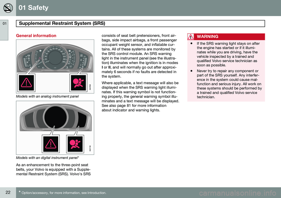
As an enhancement to the three-point seat belts, your Volvo is equipped with a Supple-mental Restraint System (SRS). Volvo's SRS consists of seat belt pretensioners, front air-bags, side impact airbags, a front passengeroccupant weight sensor, and inflatable cur-tains. All of these systems are monitored bythe SRS control module. An SRS warninglight in the instrument panel (see the illustra-tion) illuminates when the ignition is in modes I
or II, and will normally go out after approxi-
mately 6 seconds if no faults are detected in the system. Where applicable, a text message will also be displayed when the SRS warning light illumi-nates. If this warning symbol is not function-ing properly, the general warning symbol illu-minates and a text message will be displayed.See also page 81 for more informationabout indicator and warning lights.
WARNING
• If the SRS warning light stays on after the engine has started or if it illumi-nates while you are driving, have thevehicle inspected by a trained andqualified Volvo service technician assoon as possible.
• Never try to repair any component orpart of the SRS yourself. Any interfer-ence in the system could cause mal-function and serious injury. All work onthese systems should be performed bya trained and qualified Volvo servicetechnician.
Page 25 of 406
01 Safety
Supplemental Restraint System (SRS)01
}}
23
WARNING
If your vehicle has become flood-damaged in any way (e.g., soaked carpeting/stand-ing water on the floor of the vehicle), donot attempt to start the vehicle or insertthe remote key into the ignition slot beforedisconnecting the battery (see below). Thismay cause airbag deployment which couldresult in serious injury. Have the vehicletowed to a trained and qualified Volvoservice technician for repairs. Before attempting to tow the vehicle:
1. Switch off the ignition for at least10 minutes and disconnect the bat- tery.
2. Follow the instructions for manually overriding the shiftlock system onpage 128.
Front airbags
G018665
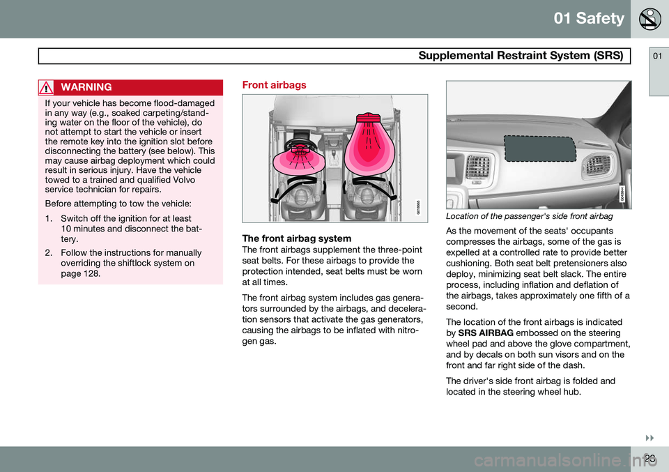
The front airbag systemThe front airbags supplement the three-point seat belts. For these airbags to provide theprotection intended, seat belts must be wornat all times. The front airbag system includes gas genera- tors surrounded by the airbags, and decelera-tion sensors that activate the gas generators,causing the airbags to be inflated with nitro-gen gas.
Location of the passenger's side front airbag
As the movement of the seats' occupants compresses the airbags, some of the gas isexpelled at a controlled rate to provide bettercushioning. Both seat belt pretensioners alsodeploy, minimizing seat belt slack. The entireprocess, including inflation and deflation ofthe airbags, takes approximately one fifth of asecond. The location of the front airbags is indicated by SRS AIRBAG embossed on the steering
wheel pad and above the glove compartment,and by decals on both sun visors and on thefront and far right side of the dash. The driver's side front airbag is folded and located in the steering wheel hub.
Page 29 of 406
01 Safety
Occupant Weight Sensor01
}}
27
General information
2
2
G017724
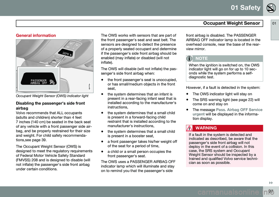
Occupant Weight Sensor (OWS) indicator light
Disabling the passenger's side frontairbag
Volvo recommends that ALL occupants (adults and children) shorter than 4 feet7 inches (140 cm) be seated in the back seatof any vehicle with a front passenger side air-bag, and be properly restrained for their sizeand weight. For child safety recommenda-tions,see page 39. The Occupant Weight Sensor (OWS) is designed to meet the regulatory requirementsof Federal Motor Vehicle Safety Standard(FMVSS) 208 and is designed to disable (willnot inflate) the passenger's side front airbagunder certain conditions. The OWS works with sensors that are part ofthe front passenger's seat and seat belt. Thesensors are designed to detect the presenceof a properly seated occupant and determineif the passenger's side front airbag should beenabled (may inflate) or disabled (will notinflate). The OWS will disable (will not inflate) the pas- senger's side front airbag when:
• the front passenger's seat is unoccupied, or has small/medium objects in the frontseat,
• the system determines that an infant ispresent in a rear-facing infant seat that isinstalled according to the manufacturer'sinstructions,
• the system determines that a small childis present in a forward-facing childrestraint that is installed according to themanufacturer's instructions,
• the system determines that a small childis present in a booster seat,
• a front passenger takes his/her weight offof the seat for a period of time,
• a child or a small person occupies thefront passenger's seat.
The OWS uses a PASSENGER AIRBAG OFF indicator lamp which will illuminate and stayon to remind you that the passenger's side front airbag is disabled. The PASSENGERAIRBAG OFF indicator lamp is located in theoverhead console, near the base of the rear-view mirror.
NOTE
When the ignition is switched on, the OWS indicator light will go on for up to 10 sec-onds while the system performs a self-diagnostic test.
However, if a fault is detected in the system:
• The OWS indicator light will stay on
• The SRS warning light (see page 22) will come on and stay on
• The message
Pass. Airbag OFF Service
urgent will be displayed in the informa-
tion display.
WARNING
If a fault in the system is detected and indicated as described, be aware that thepassenger's side front airbag will notdeploy in the event of a collision. In thiscase, the SRS system and OccupantWeight Sensor should be inspected by atrained and qualified Volvo service techni-cian as soon as possible.
Page 38 of 406
01 Safety
Crash mode 01
36* Option/accessory, for more information, see Introduction.
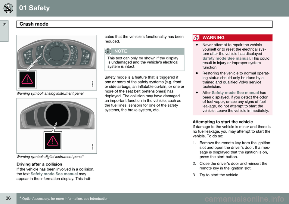
Warning symbol: analog instrument panel
Warning symbol: digital instrument panel*
Driving after a collisionIf the vehicle has been involved in a collision, the text Safety mode See manual may
appear in the information display. This indi- cates that the vehicle's functionality has been reduced.
NOTE
This text can only be shown if the display is undamaged and the vehicle's electricalsystem is intact.
Safety mode is a feature that is triggered if one or more of the safety systems (e.g. frontor side airbags, an inflatable curtain, or one ormore of the seat belt pretensioners) hasdeployed. The collision may have damagedan important function in the vehicle, such asthe fuel lines, sensors for one of the safetysystems, the brake system, etc.
WARNING
•
Never attempt to repair the vehicle yourself or to reset the electrical sys-tem after the vehicle has displayed
Safety mode See manual. This could
result in injury or improper system function.
• Restoring the vehicle to normal operat-ing status should only be done by atrained and qualified Volvo servicetechnician.
• After
Safety mode See manual has
been displayed, if you detect the odor of fuel vapor, or see any signs of fuelleakage, do not attempt to start thevehicle. Leave the vehicle immediately.
Attempting to start the vehicleIf damage to the vehicle is minor and there is no fuel leakage, you may attempt to start thevehicle. To do so:
1. Remove the remote key from the ignition
slot and open the driver's door. If a mes- sage is displayed that the ignition is on,press the start button.
2. Close the driver's door and reinsert the remote key in the ignition slot.
3. Try to start the vehicle.
Page 58 of 406
02 Locks and alarm
Remote key and key blade
02
56
Introduction
Two remote keys or optional Personal Car Communicators (PCC) are provided with yourvehicle. They enable you to unlock the doorsand trunk, and also function as ignition keysto start the vehicle or operate electrical com-ponents. The remote keys contain detachablemetal key blades for manually locking orunlocking the driver's door and the glovecompartment. The visible ends of these keyblades are unique to make it easier to identify"your" remote key. Up to six remotes can beprogrammed for use on the same vehicle. The PCCs have enhanced functionality com- pared with the standard remote key.
NOTE
In the remainder of this chapter, all refer- ences to the remote key also pertain to thePCC unless otherwise stated.
WARNING
Never leave the remote key in the ignition slot if children are to remain in the vehicle.
See page 88 for more information on the various ignition modes.
Detachable key bladeEach remote key or PCC contains a detacha-ble metal key blade for mechanically lockingor unlocking the driver's door and the glovecompartment, and to enable the valet lockingfunction. See page 62 for more informationon the key blade and see page 65 for infor-mation on the valet locking function. The keyblades have a unique code, which is used ifnew ones need to be produced. This code isavailable at an authorized Volvo retailer. The visible ends of these key blades are unique to make it easier to identify "your"remote key.
Loss of a remote keyIf either of the remote keys is lost, the othershould be taken with the car to a Volvoretailer. As an anti-theft measure, the code ofthe lost remote key must be erased from thesystem.
NOTE
Additional or duplicate remote control keys can be obtained from any AuthorizedVolvo Retailer. You can also obtain additional or duplicate remote control keys from certain inde-pendent repair facilities and locksmithsthat are qualified to make remote controlkeys. Each key must be programmed towork with your vehicle. California Only: A list of independent repair facilities and/or locksmiths known to Volvo that can cutand code replacement keys can be found:
• on the Volvo website at http://www.volvocars.com/us/keys
• by calling Volvo Customer Care at1-800-458-1552
The number of registered keys for the vehicle can be found by pressing
MY CAR and going
into
SettingsInformationNumber of
keys. See page 215 for a description of the
menu system. USA-5WK49264FCC ID:KR55WK49264 + Siemens VDO 5WK49236 FCC ID:KR55WK49236, 5WK49266
Page 60 of 406
02 Locks and alarm
Remote key and key blade
02
58
•To activate visual confirmation: go to
SettingsCar settingsLight
settings and select Door lock
confirmation light and/or Unlock
confirmation light by pressing OK/
MENU .
• To activate audible confirmation: go to
SettingsCar settingsLock
settings and select Audible
confirmation by pressing OK/MENU.
See page 215 for a description of the menu system.
Lock indicator
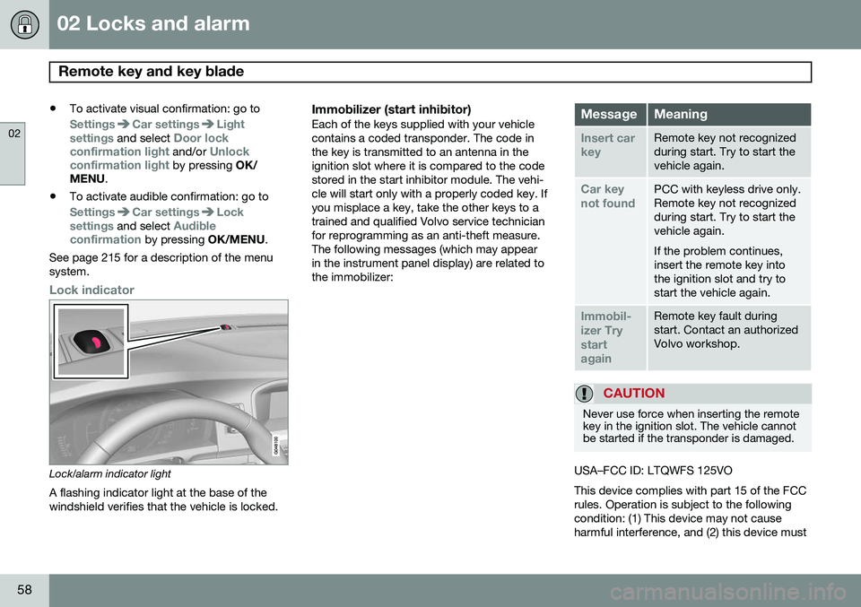
Lock/alarm indicator light
A flashing indicator light at the base of the windshield verifies that the vehicle is locked.
Immobilizer (start inhibitor)Each of the keys supplied with your vehiclecontains a coded transponder. The code inthe key is transmitted to an antenna in theignition slot where it is compared to the codestored in the start inhibitor module. The vehi-cle will start only with a properly coded key. Ifyou misplace a key, take the other keys to atrained and qualified Volvo service technicianfor reprogramming as an anti-theft measure.The following messages (which may appearin the instrument panel display) are related tothe immobilizer:MessageMeaning
Insert car keyRemote key not recognized during start. Try to start thevehicle again.
Car key not foundPCC with keyless drive only. Remote key not recognizedduring start. Try to start thevehicle again. If the problem continues, insert the remote key intothe ignition slot and try tostart the vehicle again.
Immobil- izer TrystartagainRemote key fault during start. Contact an authorizedVolvo workshop.
CAUTION
Never use force when inserting the remote key in the ignition slot. The vehicle cannotbe started if the transponder is damaged.
USA–FCC ID: LTQWFS 125VO This device complies with part 15 of the FCC rules. Operation is subject to the followingcondition: (1) This device may not causeharmful interference, and (2) this device must
Page 62 of 406
02 Locks and alarm
Remote key and key blade
02
60* Option/accessory, for more information, see Introduction.
After a short pause, press the Unlock button a second time within 10 seconds to unlockthe other doors and the trunk. This function can be changed so that all doors unlock at the same time by pressing My Car and going to
SettingsCar
settings
Lock settingsChange doors
unlock setting. See page 215 for a descrip-
tion of the menu system.
Approach lighting – As you approach
the vehicle, press the button on the remote key to light the interior lighting, parking lights,license plate lighting and the lights in the doormirrors*. These lights will switch off automatically after 30, 60 or 90 seconds. See page 215 for adescription of the menu system.
Unlock/open trunk
Press once: This unlocks the trunk (but does
not open it) and disarms the alarm (the alarm indicator light on the dashboard will go out). Ifthe trunk is not opened within two minutes itwill automatically relock and the alarm will berearmed. Press twice: This both unlocks the trunk and
pops it open slightly.
NOTE
Any excess weight (snow, etc.) on the trunk lid may prevent it from opening.
See also page 72 for information on open- ing the trunk from the passenger compart-ment. After closing, the trunk will not automatically relock. Press Lock to relock it and rearm thealarm.
Panic alarm – This button can be used
to attract attention during emergency situa- tions. To activate the panic alarm, press and hold this button for at least 3 seconds or press ittwice within 3 seconds. The turn signals andhorn will be activated. The panic alarm willstop automatically after 2 minutes and45 seconds. To deactivate, wait approximately 5 seconds and press the button again. The Panic alarm button will not unlock the vehicle.
RangeThe remote key has a range of approximately60 ft. (20 m) from the vehicle.
NOTE
Buildings or other obstacles may interfere with the function of the remote key. Thevehicle can also be locked or unlockedwith the key blade, see page 62.
If the remote key is removed from the vehicle while the engine is running or if the ignition isin mode I or II and all of the doors are closed,
a message will appear in the instrument paneldisplay and there will be an audible signal. When the remote key is returned to the vehi- cle, the message will be erased and the audi-ble signal will stop after one of the followinghas been done: • The remote key is inserted in the ignition slot
• The vehicle's speed exceeds 20 mph(30 km/h)
• The
OK button on the left steering wheel
lever is pressed
Page 65 of 406
02 Locks and alarm
Remote key and key blade
02
}}
* Option/accessory, for more information, see Introduction.63
Unlocking the driver's door with the detached key blade
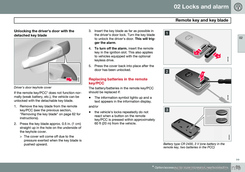
Driver's door keyhole cover
If the remote key/PCC* does not function nor- mally (weak battery, etc.), the vehicle can beunlocked with the detachable key blade.
1. Remove the key blade from the remote key/PCC (see the previous section, "Removing the key blade" on page 62 forinstructions).
2. Press the key blade approx. 0.5 in. (1 cm) straight up in the hole on the underside ofthe keyhole cover.
> The cover will come off due to thepressure exerted when the key blade is pushed upward. 3. Insert the key blade as far as possible in
the driver's door lock. Turn the key bladeto unlock the driver's door. This will trig-
ger the alarm .
4. To turn off the alarm , insert the remote
key in the ignition slot. This also appliesto vehicles equipped with the optionalkeyless drive.
5. Press the cover back into place after the door has been unlocked.
Replacing batteries in the remote key/PCC
The battery/batteries in the remote key/PCC should be replaced if: •The information symbol lights up and a text appears in the information display.
and/or
• the vehicle's locks repeatedly do notreact when a button on the remotekey/PCC is pressed within approximately60 ft (20 m) from the vehicle.
Battery type CR 2430, 3 V (one battery in the remote key, two batteries in the PCC)