display VOLVO S60 2018 Owner´s Manual
[x] Cancel search | Manufacturer: VOLVO, Model Year: 2018, Model line: S60, Model: VOLVO S60 2018Pages: 396, PDF Size: 9.4 MB
Page 39 of 396
SAFETY
}}
37
NOTE
When the ignition is switched on, the OWS indicator light will illuminate for several sec-onds while the system performs a self-diag-nostic test.
However, if a fault is detected in the system:
• The OWS indicator light will stay on
• The SRS warning light (p. 31) will come on and stay on
• The message
Pass. Airbag OFF Service
urgent will be displayed in the information
display.
WARNING
If a fault in the system is detected and indi- cated as described, be aware that the pas-senger's side front airbag will not deploy inthe event of a collision. In this case, the SRSsystem and Occupant Weight Sensor shouldbe inspected by a trained and qualified Volvoservice technician as soon as possible.
WARNING
• Never try to open, remove, or repair any components in the OWS system. Thiscould result in system malfunction. Main-tenance or repairs should only be carriedout by an a trained and qualified Volvoservice technician.
• The front passenger's seat should not bemodified in any way. This could reducepressure on the seat cushion, whichmight interfere with the OWS system'sfunction.
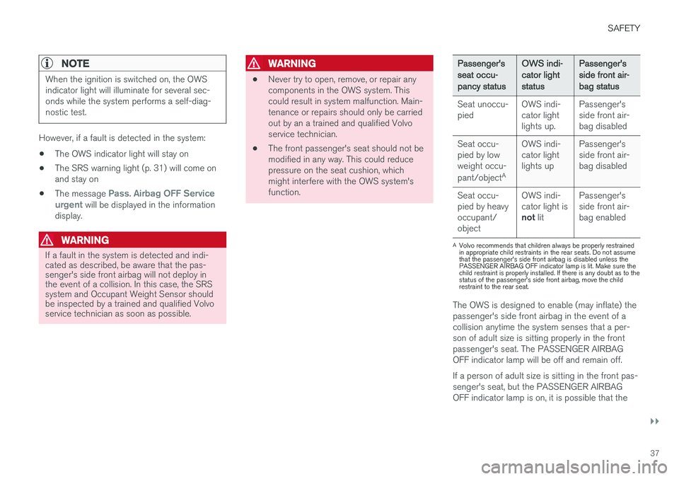
Passenger's seat occu-pancy status OWS indi-cator lightstatusPassenger'sside front air-bag status
Seat unoccu- pied OWS indi-cator lightlights up.Passenger'sside front air-bag disabled
Seat occu-pied by lowweight occu- pant/object AOWS indi-
cator light lights up Passenger'sside front air-
bag disabled
Seat occu-pied by heavyoccupant/object OWS indi-cator light is
not lit Passenger'sside front air-bag enabled
A
Volvo recommends that children always be properly restrained in appropriate child restraints in the rear seats. Do not assumethat the passenger's side front airbag is disabled unless thePASSENGER AIRBAG OFF indicator lamp is lit. Make sure thechild restraint is properly installed. If there is any doubt as to thestatus of the passenger's side front airbag, move the childrestraint to the rear seat.
The OWS is designed to enable (may inflate) the passenger's side front airbag in the event of acollision anytime the system senses that a per-son of adult size is sitting properly in the frontpassenger's seat. The PASSENGER AIRBAGOFF indicator lamp will be off and remain off. If a person of adult size is sitting in the front pas- senger's seat, but the PASSENGER AIRBAGOFF indicator lamp is on, it is possible that the
Page 46 of 396
||
SAFETY
* Option/accessory.
44
WARNING
Any contact between the front seat backrests and the folded rear seat or a rear-facing childseat could impede the function of the WHIPSsystem. If the rear seat is folded down, theoccupied front seats must be adjusted for-ward so that they do not touch the folded rearseat.
Related information
• Seat belts – general (p. 28)
Crash mode – general information
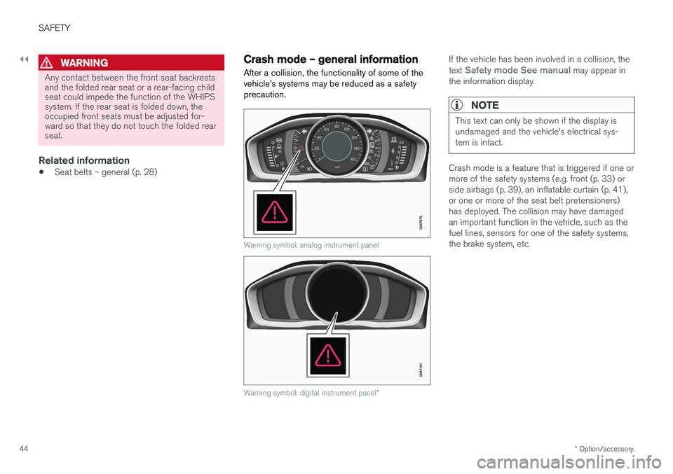
After a collision, the functionality of some of the vehicle's systems may be reduced as a safetyprecaution.
Warning symbol: analog instrument panel
Warning symbol: digital instrument panel *
If the vehicle has been involved in a collision, the text Safety mode See manual may appear in
the information display.
NOTE
This text can only be shown if the display is undamaged and the vehicle's electrical sys-tem is intact.
Crash mode is a feature that is triggered if one or more of the safety systems (e.g. front (p. 33) orside airbags (p. 39), an inflatable curtain (p. 41),or one or more of the seat belt pretensioners)has deployed. The collision may have damagedan important function in the vehicle, such as thefuel lines, sensors for one of the safety systems,the brake system, etc.
Page 47 of 396
SAFETY
45
WARNING
•Never attempt to repair the vehicle your- self or to reset the electrical system after the vehicle has displayed
Safety mode
See manual. This could result in injury or
improper system function.
• Restoring the vehicle to normal operating status should only be done by a trainedand qualified Volvo service technician.
• After
Safety mode See manual has
been displayed, if you detect the odor of fuel vapor, or see any signs of fuel leak-age, do not attempt to start the vehicle.Leave the vehicle immediately.
Related information
• Crash mode – starting the vehicle (p. 45)
• Crash mode – moving the vehicle (p. 45)
Crash mode – starting the vehicle
If Crash mode has been set Crash mode (p. 44)) and damage to the vehicle isminor and there is no fuel leakage, you mayattempt to start the engine.
To do so:
1. Remove the remote key from the ignition slot and open the driver's door. If a message is displayed that the ignition is on, press thestart button.
2. Close the driver's door and reinsert the remote key in the ignition slot.
3. Try to start the vehicle.
WARNING
If the message Safety mode See manual is
still displayed, the vehicle should not be driven and must be towed. Concealed faults maymake the vehicle difficult to control.
Related information
• Crash mode – general information (p. 44)
• Crash mode – moving the vehicle (p. 45)
Crash mode – moving the vehicle
If the message
Normal mode appears after an
attempt has been made to start the engine, Star- ting the vehicle after a crash (p. 45), the vehiclemay be moved carefully from its present position,if for example, it is blocking traffic. It should,however, not be moved farther than is absolutelynecessary.
WARNING
Even if the vehicle appears to be drivable after Crash mode has been set, it should not bedriven or towed (pulled by another vehicle).There may be concealed damage that couldmake it difficult or impossible to control. Thevehicle should be transported on a flatbedtow truck to a trained and qualified Volvoservice technician for inspection/repairs.
Related information
• Crash mode – general information (p. 44)
Page 62 of 396
INSTRUMENTS AND CONTROLS
60
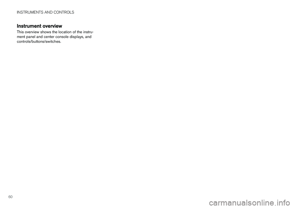
Instrument overview This overview shows the location of the instru- ment panel and center console displays, andcontrols/buttons/switches.
Page 64 of 396
||
INSTRUMENTS AND CONTROLS
* Option/accessory.
62
Function See
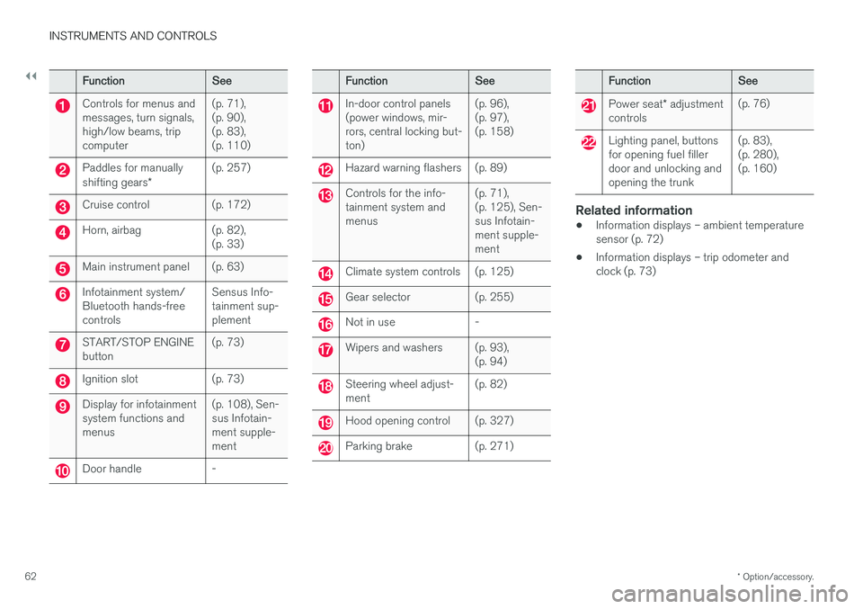
Controls for menus and messages, turn signals,high/low beams, tripcomputer(p. 71),(p. 90),(p. 83),(p. 110)
Paddles for manually shifting gears
*(p. 257)
Cruise control (p. 172)
Horn, airbag (p. 82),
(p. 33)
Main instrument panel (p. 63)
Infotainment system/ Bluetooth hands-freecontrolsSensus Info-tainment sup-plement
START/STOP ENGINE button
(p. 73)
Ignition slot (p. 73)
Display for infotainment system functions andmenus(p. 108), Sen-sus Infotain-ment supple-ment
Door handle -
Function
See
In-door control panels (power windows, mir-rors, central locking but-ton)(p. 96),(p. 97),(p. 158)
Hazard warning flashers (p. 89)
Controls for the info- tainment system andmenus
(p. 71),(p. 125), Sen-sus Infotain-ment supple-ment
Climate system controls (p. 125)
Gear selector (p. 255)
Not in use -
Wipers and washers (p. 93),
(p. 94)
Steering wheel adjust- ment(p. 82)
Hood opening control (p. 327)
Parking brake (p. 271)
Function
See
Power seat* adjustment
controls (p. 76)
Lighting panel, buttons for opening fuel fillerdoor and unlocking andopening the trunk(p. 83),(p. 280),(p. 160)
Related information
•
Information displays – ambient temperature sensor (p. 72)
• Information displays – trip odometer andclock (p. 73)
Page 65 of 396
INSTRUMENTS AND CONTROLS
}}
* Option/accessory.63
Information displays – introduction
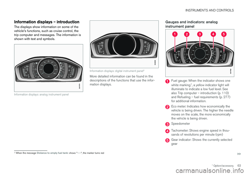
The displays show information on some of the vehicle's functions, such as cruise control, thetrip computer and messages. The information isshown with text and symbols.
Information displays: analog instrument panel
Information displays: digital instrument panel *
More detailed information can be found in the descriptions of the functions that use the infor-mation displays.
Gauges and indicators: analog instrument panel
Fuel gauge: When the indicator shows one white marking1
, a yellow indicator light will
illuminate to indicate a low fuel level. See also Trip computer – introduction (p. 110)and Refueling – fuel requirements (p. 277)for additional information.
Eco meter: Indicates how economically the vehicle is being driven. The higher the needlemoves on the scale, the more economicallythe vehicle is being driven.
Speedometer
Tachometer: Shows engine speed in thou- sands of revolutions per minute (rpm)
Gear indicator: Shows the currently selected gear
1 When the message Distance to empty fuel tank: shows "----", the marker turns red
Page 66 of 396
||
INSTRUMENTS AND CONTROLS
* Option/accessory.
64
Gauges and indicators: digital instrument panel *
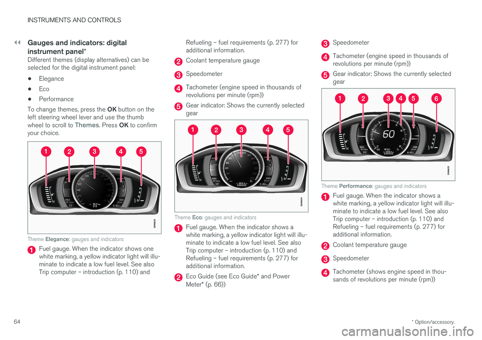
Different themes (display alternatives) can be selected for the digital instrument panel:
• Elegance
• Eco
• Performance
To change themes, press the OK button on the
left steering wheel lever and use the thumb wheel to scroll to
Themes. Press OK to confirm
your choice.
Theme Elegance : gauges and indicators
Fuel gauge. When the indicator shows one white marking, a yellow indicator light will illu-minate to indicate a low fuel level. See alsoTrip computer – introduction (p. 110) and Refueling – fuel requirements (p. 277) foradditional information.
Coolant temperature gauge
Speedometer
Tachometer (engine speed in thousands of revolutions per minute (rpm))
Gear indicator: Shows the currently selected gear
Theme
Eco: gauges and indicators
Fuel gauge. When the indicator shows a white marking, a yellow indicator light will illu-minate to indicate a low fuel level. See alsoTrip computer – introduction (p. 110) andRefueling – fuel requirements (p. 277) foradditional information.
Eco Guide (see Eco Guide * and Power
Meter * (p. 66))
Speedometer
Tachometer (engine speed in thousands of revolutions per minute (rpm))
Gear indicator: Shows the currently selected gear
Theme Performance : gauges and indicators
Fuel gauge. When the indicator shows a white marking, a yellow indicator light will illu-minate to indicate a low fuel level. See alsoTrip computer – introduction (p. 110) andRefueling – fuel requirements (p. 277) foradditional information.
Coolant temperature gauge
Speedometer
Tachometer (shows engine speed in thou- sands of revolutions per minute (rpm))
Page 67 of 396
INSTRUMENTS AND CONTROLS
* Option/accessory.65
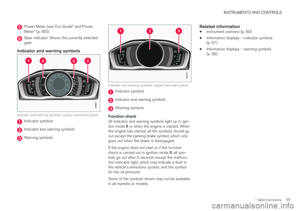
Power Meter (see Eco Guide * and Power
Meter * (p. 66)).
Gear indicator: Shows the currently selected gear
Indicator and warning symbols
Indicator and warning symbols: analog instrument panel
Indicator symbols
Indicator and warning symbols
Warning symbols
Indicator and warning symbols: digital instrument panel
Indicator symbols
Indicator and warning symbols
Warning symbols
Function check
All indicator and warning symbols light up in igni- tion mode II or when the engine is started. When
the engine has started, all the symbols should go out except the parking brake symbol, which onlygoes out when the brake is disengaged. If the engine does not start or if the function check is carried out in ignition mode II, all sym-
bols go out after 5 seconds except the malfunc- tion indicator light, which may indicate a fault inthe vehicle's emissions system, and the symbolfor low oil pressure. Some of the symbols shown may not be available in all markets or models.
Related information
• Instrument overview (p. 60)
• Information displays – indicator symbols(p. 67)
• Information displays – warning symbols(p. 69)
Page 68 of 396
INSTRUMENTS AND CONTROLS
* Option/accessory.
66
Eco Guide * and Power Meter *
Eco guide and Power guide are two gauges in the instrument panel that help improve drivingeconomy. The vehicle also stores driving-related statistics in the form of a bar graph, see Trip computer –Trip statistics (p. 117).
Introduction
To display or remove these functions from the instrument panel, select the "Eco" theme (seeInformation displays – introduction (p. 63)). Driving statistics are also stored and can be dis- played in the form of a bar chart (see Trip com-puter – Trip statistics (p. 117)).
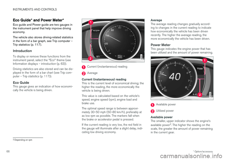
Eco GuideThis gauge gives an indication of how economi-cally the vehicle is being driven.
Current (instantaneous) reading
Average
Current (instantaneous) reading
This is the current level of economical driving; the higher the reading, the more economically thevehicle is being driven. This value is calculated based on the vehicle's speed, engine speed (rpm), engine load andbrake use. The optimal speed range is between approxi- mately 30–50 mph (50–80 km/h), preferably atas low rpm as possible. The markers fall whenthe brake or accelerator pedal is pressed. If the current reading is very low, the red field in the gauge will illuminate after a slight delay, indi-cating low driving economy.
Average
The average reading changes gradually accord- ing to changes in the current reading to indicatehow economically the vehicle has been drivenrecently. The higher the average reading, themore economically the vehicle has been driven.
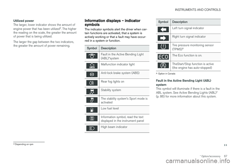
Power MeterThis gauge indicates the engine power that hasbeen utilized and the amount of power remaining.
Available power
Utilized power
Available power
The smaller, upper indicator shows the engine's available power 2
. The higher the reading on the
scale, the greater the amount of power remaining in the current gear.
2 Depending on rpm
Page 69 of 396
INSTRUMENTS AND CONTROLS
}}
* Option/accessory.67
Utilized power
The larger, lower indicator shows the amount of engine power that has been utilized 2
. The higher
the reading on the scale, the greater the amount of power that is being utilized. The larger the gap between the two indicators, the greater the amount of power remaining.Information displays – indicator symbols
The indicator symbols alert the driver when cer- tain functions are activated, that a system isactively working or that a fault may have occur-red in a system or function.
Symbol Description
Fault in the Active Bending Light (ABL)*system
Malfunction indicator light
Anti-lock brake system (ABS)
Rear fog lights on
Stability system
The stability system's Sport mode is activated
Low fuel level
Information symbol, read the text displayed in the instrument panel
High beam indicator
Symbol Description
Left turn signal indicator
Right turn signal indicator
Tire pressure monitoring sensor (TPMS)A
The Eco function is on.
TheStart/Stop function is active (the engine has auto-stopped)
A
Option in Canada
Fault in the Active Bending Light (ABL)
system
This symbol will illuminate if there is a fault in the ABL system. See Active Bending Lights (ABL) *
(p. 86) for more information about this system.
2 Depending on rpm