VOLVO S90 2017 Owner´s Manual
Manufacturer: VOLVO, Model Year: 2017, Model line: S90, Model: VOLVO S90 2017Pages: 548, PDF Size: 11.42 MB
Page 461 of 548
WHEELS AND TIRES
}}
459
6. Tap the calibration button. 7.
Tap
OK after the tire pressure in all four tires
has been checked and adjusted.
8. Drive the vehicle. > The calibration process will be completedwhile driving and will be interrupted if the vehicle is parked and the engine isswitched off. Calibration continues auto-matically when driving resumes.
When enough data has been collected to detecta low tire pressure situation, the tires' color in thecenter display will change to green. The systemwill not give any text confirmation when calibra-tion is finished although it will state if calibrationfails. When driving with heavy loads or at sus-tained highway speeds, the tire pressure shouldbe adjusted to the recommended inflation pres-sures. After adjusting inflation pressure, repeat steps 1-8.
NOTE
Always remember to calibrate the Tire Pres- sure Monitoring System when the wheelshave been changed or the tire inflation pres-sure has been corrected according to the tirepressure decal or tire inflation pressure table. If correct reference values have not been set, the system cannot issue low tire pressurealerts correctly. The vehicle must be parked with the engine running to access the calibration button andto start the calibration process.
WARNING
The exhaust gases contain carbon monoxide, which is invisible and odorless but very poi-sonous. For this reason, always perform thecalibration procedure outdoors or in a work-shop with exhaust gas evacuation equipment.
Related information
• Tire Pressure Monitoring System (TPMS) (p. 455)
Tire sealing system 6
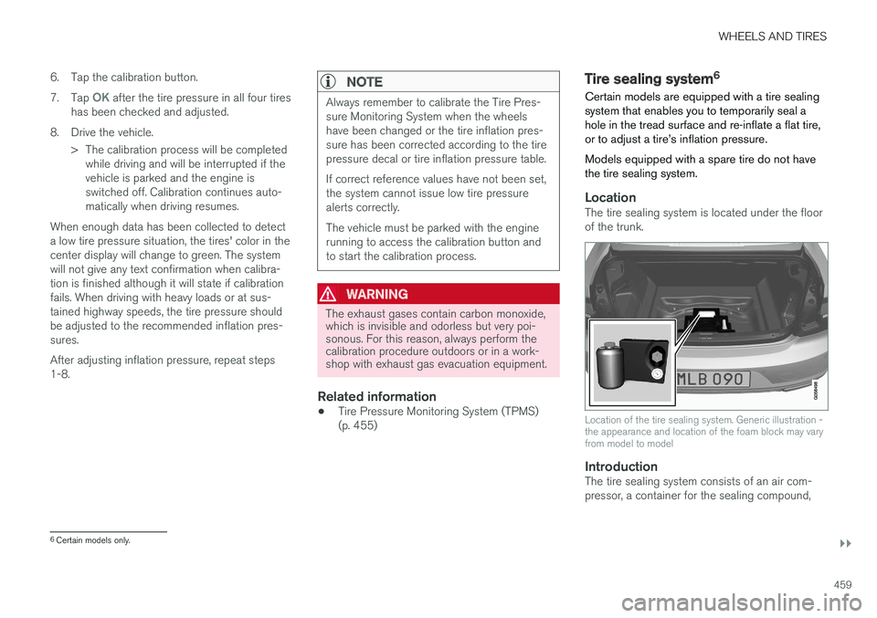
Certain models are equipped with a tire sealing system that enables you to temporarily seal ahole in the tread surface and re-inflate a flat tire,or to adjust a tire
Page 462 of 548
||
WHEELS AND TIRES
* Option/accessory.
460 wiring to connect the system to the vehicle
Page 463 of 548
WHEELS AND TIRES
}}
461
WARNING
Please keep the following points in mind when using the tire sealing system:
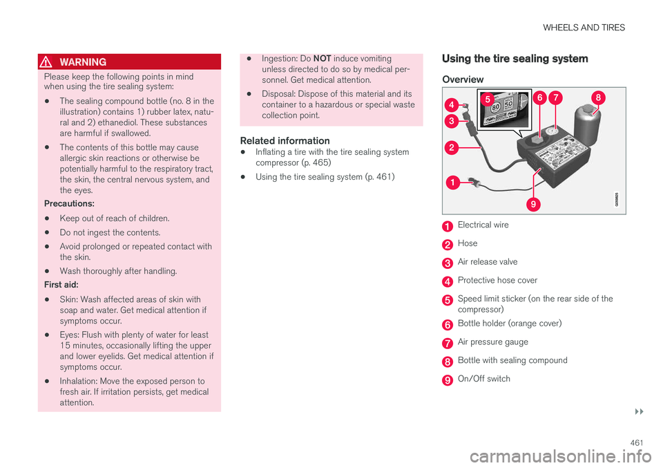
• The sealing compound bottle (no. 8 in the illustration) contains 1) rubber latex, natu-ral and 2) ethanediol. These substancesare harmful if swallowed.
• The contents of this bottle may causeallergic skin reactions or otherwise bepotentially harmful to the respiratory tract,the skin, the central nervous system, andthe eyes.
Precautions: • Keep out of reach of children.
• Do not ingest the contents.
• Avoid prolonged or repeated contact with the skin.
• Wash thoroughly after handling.
First aid: • Skin: Wash affected areas of skin with soap and water. Get medical attention ifsymptoms occur.
• Eyes: Flush with plenty of water for least15 minutes, occasionally lifting the upperand lower eyelids. Get medical attention ifsymptoms occur.
• Inhalation: Move the exposed person tofresh air. If irritation persists, get medicalattention.
•
Ingestion: Do
NOT induce vomiting
unless directed to do so by medical per- sonnel. Get medical attention.
• Disposal: Dispose of this material and itscontainer to a hazardous or special wastecollection point.
Related information
•Inflating a tire with the tire sealing systemcompressor (p. 465)
• Using the tire sealing system (p. 461)
Using the tire sealing system
Overview
Electrical wire
Hose
Air release valve
Protective hose cover
Speed limit sticker (on the rear side of the compressor)
Bottle holder (orange cover)
Air pressure gauge
Bottle with sealing compound
On/Off switch
Page 464 of 548
||
WHEELS AND TIRES
462
Connecting
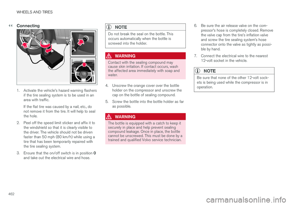
1. Activate the vehicle's hazard warning flashersif the tire sealing system is to be used in an area with traffic. If the flat tire was caused by a nail, etc., do not remove it from the tire. It will help to sealthe hole.
2. Peel off the speed limit sticker and affix it to the windshield so that it is clearly visible tothe driver. The vehicle should not be drivenfaster than 50 mph (80 km/h) while using atire that has been temporarily repaired withthe tire sealing system.
3. Ensure that the on/off switch is in position 0
and take out the electrical wire and hose.
NOTE
Do not break the seal on the bottle. This occurs automatically when the bottle isscrewed into the holder.
WARNING
Contact with the sealing compound may cause skin irritation. If contact occurs, washthe affected area immediately with soap andwater.
4. Unscrew the orange cover over the bottle holder on the compressor and unscrew the cap on the bottle of sealing compound.
5. Screw the bottle into the bottle holder as far as possible.
WARNING
The bottle is equipped with a catch to keep it securely in place and help prevent sealingcompound leakage. Once in place, the bottlecannot be unscrewed. This must be done by atrained and qualified Volvo service technician. 6. Be sure the air release valve on the com-
pressor's hose is completely closed. Remove the valve cap from the tire
Page 465 of 548
WHEELS AND TIRES
}}}}
463
8. Start the tire sealing system
Page 466 of 548
||
WHEELS AND TIRES
464
ice technician to have the bottle removed and properly disposed of.
WARNING
If heavy vibrations, unsteady steering behavior, or noises should occur while driving, reducespeed and park the vehicle in a safe place.Recheck the tire for bumps, cracks, or othervisible damage, and recheck its inflation pres-sure. If the pressure is below 19 psi (1.3 bar),do not continue driving. Have the vehicletowed to a trained and qualified Volvo servicetechnician.
15. Rechecking the pressure Reconnect the tire sealing system's hose to the tire's inflation valve. 16. Without starting the compressor, check the
inflation pressure on the air pressure gauge. •If the pressure is under 19 psi (1.3 bar), the puncture has not been sealed suffi-ciently and the vehicle should not bedriven. Have the vehicle towed to a trainedand qualified Volvo service technician.
• If the pressure is more than 19 psi(1.3 bar), connect the electrical wire to a12-volt socket, start the compressor andinflate the tire to the correct pressure(see the tire pressure decal on the on thedriver's side B-pillar (the structural mem-ber at the side of the vehicle, at the rearof the driver's door opening). Use the airrelease valve to release some air from thetire if necessary.
17. Switch off the compressor and disconnect the electrical wire from the 12-volt socket.Unscrew the hose from the tire
Page 467 of 548
WHEELS AND TIRES
}}
465
WARNING
•After using the tire sealing system, the vehicle should not be driven farther thanapproximately 120 miles (200 km).
• Have the tire inspected by a trained andqualified Volvo service technician as soonas possible to determine if it can be per-manently repaired or must be replaced.
• The vehicle should not be driven fasterthan 50 mph (80 km/h) while using a tirethat has been temporarily repaired withthe tire sealing system.
• After using the tire sealing system, drivecarefully and avoid abrupt steeringmaneuvers and sudden stops.
Related information
• Tire sealing system (p. 459)
• Checking tire inflation pressure (p. 448)
Inflating a tire with the tire sealing system compressor
The compressor can be used to inflate a tire.
1. The compressor should be switched off. Ensure that the on/off switch is in position 0.
Take out the electrical wire and hose.
2. Be sure the air release valve on the com- pressor's hose is completely closed. Remove the valve cap from the tire
Page 468 of 548
||
WHEELS AND TIRES
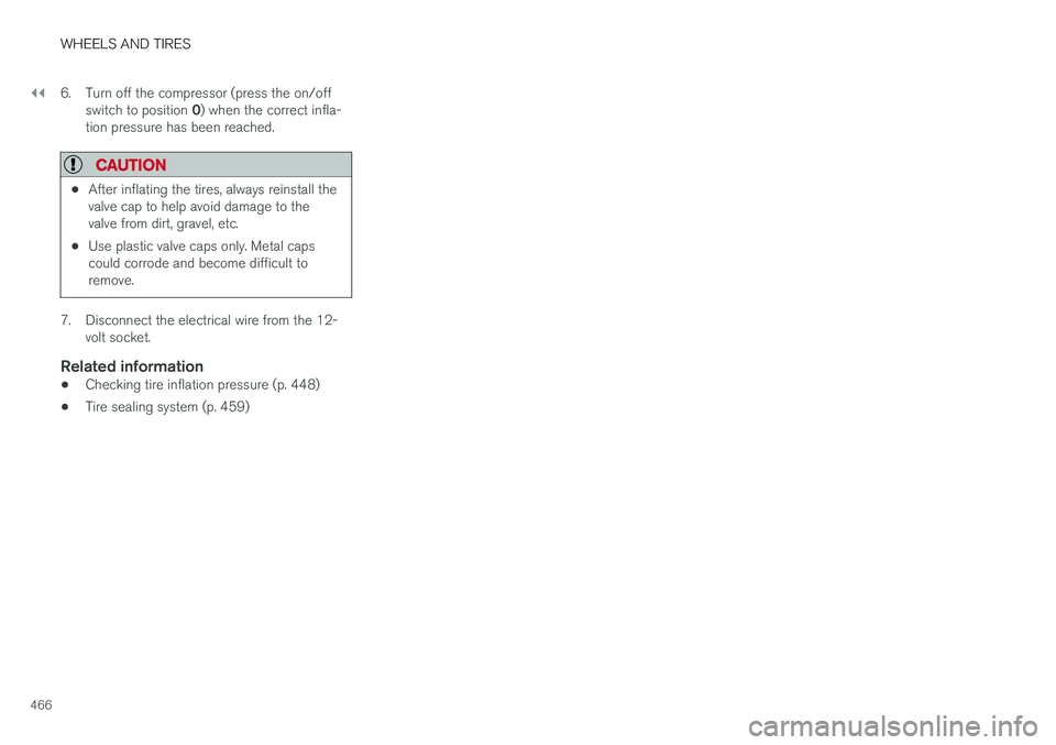
4666. Turn off the compressor (press the on/off
switch to position 0) when the correct infla-
tion pressure has been reached.
CAUTION
• After inflating the tires, always reinstall the valve cap to help avoid damage to thevalve from dirt, gravel, etc.
• Use plastic valve caps only. Metal capscould corrode and become difficult toremove.
7. Disconnect the electrical wire from the 12-
volt socket.
Related information
• Checking tire inflation pressure (p. 448)
• Tire sealing system (p. 459)
Page 469 of 548
M A I N T E N A N C E A N D S E R V I C I N G
Page 470 of 548
MAINTENANCE AND SERVICING
468
Volvo's service program
Periodic maintenance and service performed at the intervals specified in your Warranty andService Records Information booklet will helpkeep your vehicle running well.
IntroductionThe maintenance services contain several checks that require special instruments and tools andtherefore must be performed by a qualified tech-nician. To keep your Volvo in top condition, spec-ify time-tested and proven Genuine Volvo Partsand Accessories.
The Federal Clean Air Act – U.S.
The Federal Clean Air Act requires vehicle manu- facturers to furnish written instructions to the ulti-mate purchaser to assure the proper servicingand function of the components that controlemissions. These services, which are listed in the"Warranty and Service Records Information"booklet, are not covered by the warranty. You willbe required to pay for labor and material used.
Maintenance
Your Volvo passed several major inspections before it was delivered to you, in accordance withVolvo specifications. The maintenance proce-dures outlined in the Warranty and ServiceRecords Information booklet, many of which willpositively affect your vehicle's emissions, shouldbe performed as indicated. It is recommendedthat receipts for vehicle emission maintenance beretained in case questions arise concerning maintenance. Inspection and maintenance shouldalso be performed anytime a malfunction isobserved or suspected.
Applicable warranties – U.S./Canada
In accordance with applicable U.S. and Canadian regulations, the following list of warranties is pro-vided.
• New Vehicle Limited Warranty
• Parts and Accessories Limited Warranty
• Corrosion Protection Limited Warranty
• Seat Belt and Supplemental Restraint Sys-tems Limited Warranty
• Emission Design and Defect Warranty
• Emission Performance Warranty
These are the federal warranties; other warran-ties are provided as required by state/provinciallaw. Refer to your separate Warranty and ServiceRecords Information booklet for detailed informa-tion concerning each of the warranties.
Periodic maintenance helps minimize emissions
NOTE
• Refer to your Warranty and Service Records Information booklet for a com-prehensive service and maintenanceschedule up to 150,000 miles (240,000km). This program contains inspectionsand services necessary for the properfunction of your vehicle and includescomponents that affect vehicle emis-sions.
• The Warranty and Service Records Infor-mation booklet also contains detailedinformation concerning the warrantiesthat apply to your vehicle.
On-board Diagnostic SystemOBD II is part of your vehicle's computerized engine management system. It stores diagnosticinformation about your vehicle's emission con-trols. It can light the Check Engine light (MIL) if itdetects an emission control "fault." A "fault" is acomponent or system that is not performingwithin an expected range. A fault may be perma-nent or temporary. OBD II will store a messageabout any fault.