Charge VOLVO S90 2017 Owner´s Manual
[x] Cancel search | Manufacturer: VOLVO, Model Year: 2017, Model line: S90, Model: VOLVO S90 2017Pages: 548, PDF Size: 11.42 MB
Page 136 of 548
||
INSTRUMENTS AND CONTROLS
134A "png_get_copyright" function is available, for convenient use in "about" boxes and the like: printf("%s",png_get_copyright(NULL));Also, the PNG logo (in PNG format, of course) is supplied in the files "pngbar.png" and"pngbar.jpg (88x31) and "pngnow.png" (98x31). Libpng is OSI Certified Open Source Software. OSI Certified Open Source is a certification markof the Open Source Initiative. Glenn Randers-Pehrson [email protected] April 15, 2002
MIT LicenseCopyright (c)
Permission is hereby granted, free of charge, toany person obtaining a copy of this software andassociated documentation files (the "Software"),to deal in the Software without restriction,including without limitation the rights to use,copy, modify, merge, publish, distribute,sublicense, and/or sell copies of the Software,and to permit persons to whom the Software isfurnished to do so, subject to the followingconditions: The above copyright notice and this permission notice shall be included in all copies orsubstantial portions of the Software. THE SOFTWARE IS PROVIDED "AS IS", WITHOUT WARRANTY OF ANY KIND,EXPRESS OR IMPLIED, INCLUDING BUT NOT LIMITED TO THE WARRANTIES OFMERCHANTABILITY, FITNESS FOR APARTICULAR PURPOSE ANDNONINFRINGEMENT. IN NO EVENT SHALLTHE AUTHORS OR COPYRIGHT HOLDERS BELIABLE FOR ANY CLAIM, DAMAGES OROTHER LIABILITY, WHETHER IN AN ACTIONOF CONTRACT, TORT OR OTHERWISE,ARISING FROM, OUT OF OR IN CONNECTIONWITH THE SOFTWARE OR THE USE OROTHER DEALINGS IN THE SOFTWARE.
zlib LicenseThe zlib/libpng License Copyright (c)
< copyright holders >
This software is provided 'as-is', without anyexpress or implied warranty. In no event will theauthors be held liable for any damages arisingfrom the use of this software. Permission is granted to anyone to use this software for any purpose, including commercialapplications, and to alter it and redistribute itfreely, subject to the following restrictions:
1. The origin of this software must not be misrepresented; you must not claim that you wrote the original software. If you use thissoftware in a product, an acknowledgment inthe product documentation would beappreciated but is not required.
2. Altered source versions must be plainly marked as such, and must not be misrepresented as being the originalsoftware.
3. This notice may not be removed or altered from any source distribution.
SGI Free Software B License Version
2.0.
SGI FREE SOFTWARE LICENSE B (Version 2.0,Sept. 18, 2008) Copyright (C) [dates of first publication] Silicon Graphics, Inc. All Rights Reserved. Permission ishereby granted, free of charge, to any personobtaining a copy of this software and associateddocumentation files (the "Software"), to deal inthe Software without restriction, including withoutlimitation the rights to use, copy, modify, merge,publish, distribute, sublicense, and/or sell copiesof the Software, and to permit persons to whomthe Software is furnished to do so, subject to thefollowing conditions: The above copyright noticeincluding the dates of first publication and eitherthis permission notice or a reference to http://oss.sgi.com/projects/FreeB/ shall be included inall copies or substantial portions of the Software. THE SOFTWARE IS PROVIDED "AS IS", WITHOUT WARRANTY OF ANY KIND,EXPRESS OR IMPLIED, INCLUDING BUT NOTLIMITED TO THE WARRANTIES OFMERCHANTABILITY, FITNESS FOR APARTICULAR PURPOSE ANDNONINFRINGEMENT. IN NO EVENT SHALLSILICON GRAPHICS, INC. BE LIABLE FOR ANY
Page 211 of 548
LOADING AND STORAGE
}}}}
* Option/accessory.209
Electrical sockets There are two 12-volt sockets in the tunnel con- sole, a 120-volt socket on the rear side of thetunnel console, and one 12-volt socket in the trunk*.
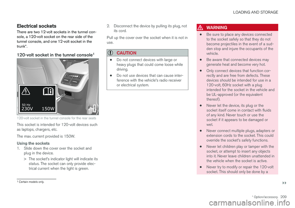
120-volt socket in the tunnel console 1
120-volt socket in the tunnel console for the rear seats
This socket is intended for 120-volt devices such as laptops, chargers, etc. The max. current provided is 150W.
Using the sockets
1. Slide down the cover over the socket and
plug in the device.
> The socket's indicator light will indicate itsstatus. The socket can only provide elec- trical current when the light is green. 2. Disconnect the device by pulling its plug, not
its cord.
Pull up the cover over the socket when it is not inuse.
CAUTION
• Do not connect devices with large or heavy plugs that could come loose whiledriving.
• Do not use devices that can cause inter-ference with the vehicle's radio receiveror electrical system.
WARNING
•
Be sure to place any devices connected to the socket safely so that they do notbecome projectiles in the event of a sud-den stop and injure the occupants of thevehicle.
• Be aware that connected devices maygenerate heat and become very hot.
• Only connect devices that function cor-rectly and are free from defects. Thesedevices should be intended for use in a120-volt, 60Hz socket with a plugintended for the socket in the vehicle andbe UL-approved (or the equivalentthereof).
• Never let the device, its plug or thesocket itself come in contact with fluidsof any kind. Never touch or use thesocket if it appears to be damaged orwet.
• Never connect multiple plugs, adapters orextension cords to the socket. This couldoverride the socket's safety functions.
• Never let children play or tamper with thesocket, or attempt to insert any objectsinto it. Never leave children unattended inthe vehicle when the socket is active.
• Never try to modify or repair the 120-voltsocket. This should only be done by a
1
Certain models only.
Page 212 of 548
||
LOADING AND STORAGE
210
trained and qualified Volvo service techni- cian.
Failure to follow the points above could result in electrical shock and/or serious injury.Status indication
An LED (Light Emitting Diode) on the socket indicates its status:
Status indicator light Socket status Action
Steady green light The socket is providing current to a connected device. None.
Flashing orange light The socket's voltage converter is too hot (the connected device draws too much current, etc. or the temperature in the passenger compartment is very high). Unplug the device, let the converter cool down and plug in the device again.
The connected device draws too much current (constantly or currently) or is notfunctioning properly. None. The device should not be plugged into thesocket.
Indicator light off The socket has not detected a plugged in device. Be sure the device is correctly plugged into the socket.
The socket is not active. Put the vehicle's ignition in at least mode I.
The socket has been active but has been deactivated. Start the engine and/or charge the start battery.
If a problem persists, have the socket checked by a trained and qualified Volvo service technician.
Page 220 of 548
||
LOCKS AND ALARM
* Option/accessory.
218 Each of the remote keys provided with the vehicle can be linked to a driver profile containing uniquepersonal settings that will be applied when thatparticular key is used. See also the article "Driverprofile" for additional information.
NOTE
Avoid placing the remote key closer than approx. (4-6 in.) (10-15 cm) to any metallicobjects or electronic devices such as cellphones, tablets, laptops or chargers.
If interference persists, unlock the vehicle with the detachable key blade and place the remotekey in the backup key reader in the tunnel con-sole cup holder to disarm the alarm.
WARNING
Always remove the remote key from the pas- senger compartment when leaving the vehicle and ensure that the ignition in mode
0, espe-
cially if there are children in the vehicle.
Key TagIn addition to the two remote keys provided, a smaller third key, called a Key Tag, is also provi-ded for vehicles equipped with the optionalPassive Entry system. This key functions in the same way as a standardremote key but does not have a detachable keyblade and its battery cannot be replaced; a newKey Tag has to be ordered.
Ordering new keysTwo remote keys are provided with the vehicle (a Key Tag
2
is also included for vehicles equipped
with the optional Passive Entry system). Addi- tional keys (a total of 12) can be ordered andused with the vehicle.
The remote key's buttons
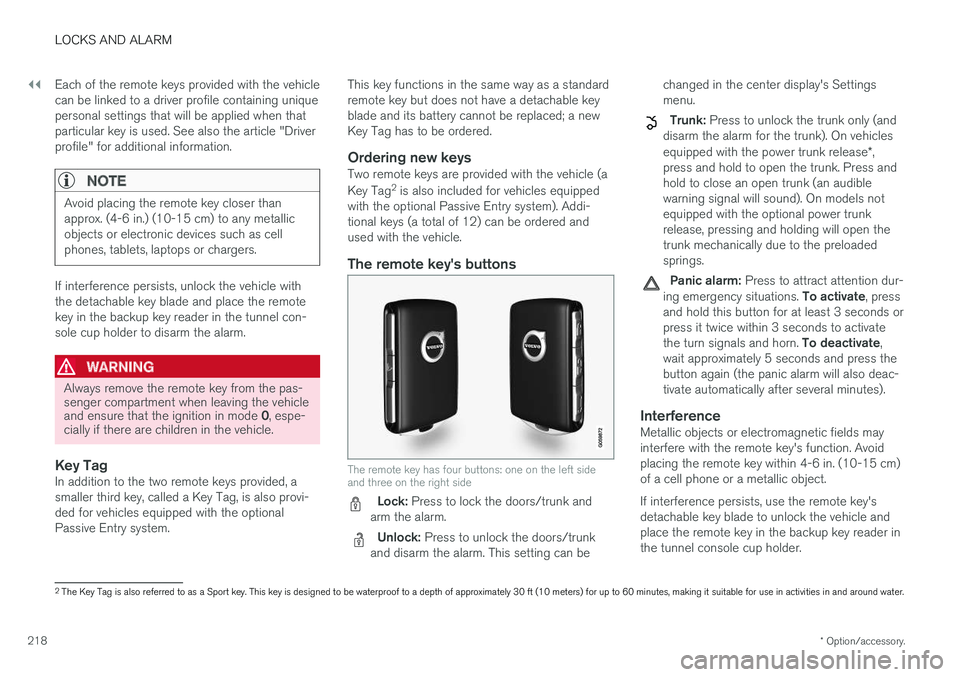
The remote key has four buttons: one on the left side and three on the right side
Lock: Press to lock the doors/trunk and
arm the alarm.
Unlock: Press to unlock the doors/trunk
and disarm the alarm. This setting can be changed in the center display's Settings menu.
Trunk: Press to unlock the trunk only (and
disarm the alarm for the trunk). On vehicles equipped with the power trunk release *,
press and hold to open the trunk. Press and hold to close an open trunk (an audiblewarning signal will sound). On models notequipped with the optional power trunkrelease, pressing and holding will open thetrunk mechanically due to the preloadedsprings.
Panic alarm: Press to attract attention dur-
ing emergency situations. To activate, press
and hold this button for at least 3 seconds or press it twice within 3 seconds to activate the turn signals and horn. To deactivate,
wait approximately 5 seconds and press the button again (the panic alarm will also deac-tivate automatically after several minutes).
InterferenceMetallic objects or electromagnetic fields mayinterfere with the remote key's function. Avoidplacing the remote key within 4-6 in. (10-15 cm)of a cell phone or a metallic object. If interference persists, use the remote key's detachable key blade to unlock the vehicle andplace the remote key in the backup key reader inthe tunnel console cup holder.
2 The Key Tag is also referred to as a Sport key. This key is designed to be waterproof to a depth of approximately 30 ft (10 meters) for up to 60 minutes, making it suitable for use in activities in and around water.
Page 355 of 548

STARTING AND DRIVING
}}
353
Parking brake malfunctions
If it has not been possible to apply or release the parking brake after several attempts, consult atrained and authorized Volvo service technicianor retailer.
An audible signal will sound if the parking brake is applied when the vehicle is being driven. If thevehicle must be parked while the parking brake isnot functioning properly: • Put the gear selector in
P.
• If the vehicle is pointing
uphill, turn the front
wheels so that they point away from the curb.
• If the vehicle is pointing
downhill, turn the
front wheels so that they point toward the curb.
• Put the gear selector in
P.
Low battery charge levelIf the battery is discharged, the parking brakecannot be operated. Connect an auxiliary batteryto the vehicle.
Replacing brake padsThe rear brake pads have to be replaced by atrained and authorized Volvo service techniciandue to the design of the electric parking brake.
Symbols in the instrument panel
Symbol Explanation
A
BIf the symbol flashes, a parking brake fault has been detected.See the message in the instru-ment panel.
A
B
Fault in the brake system.
A
US models
B Canadian models
Related information
• Using the parking brake (p. 351)
• Using the parking brake (p. 351)
• Brake functions (p. 348)
• Jump starting (p. 364)
Before a long distance trip
It is always worthwhile to have your vehicle checked by a trained and qualified Volvo servicetechnician before driving long distances. Yourretailer will also be able to supply you with bulbs,fuses, spark plugs and wiper blades for your usein the event that problems occur.
As a minimum, the following items should be checked before any long trip:
• Check that engine runs smoothly and thatfuel consumption and the oil level are normal.
• Check for fuel, oil, and fluid leakage.
• Check condition of drive belts.
• Check state of the battery's charge.
• Examine tires carefully (including the sparetire where applicable), and replace those thatare worn. Also, check tire inflation pressure.
• The brakes, front wheel alignment, and steer-ing gear should be checked by a trained andqualified Volvo service technician only.
• Check all lights, including high beams.
• Reflective warning triangles are legallyrequired in some states/provinces.
• Have a word with a trained and qualifiedVolvo service technician if you intend to drive
Page 357 of 548
STARTING AND DRIVING
}}
355
capacity weight or maximum permissible axle loads are not exceeded.
• At the specified curb weight your vehicle hasa tendency to understeer, which means thatthe steering wheel has to be turned morethan might seem appropriate for the curva-ture of a bend. This ensures good stabilityand reduces the risk of rear wheel skid.Remember that these properties can alterwith the vehicle load. The heavier the load inthe cargo compartment, the less the ten-dency to understeer.
Related information
•ECO drive mode (p. 377)
• Tire inflation pressure table (p. 532)
• Volvo and the environment (p. 15)
Driving through standing water
The vehicle should be driven with extreme cau- tion if it is necessary to drive through standingwater.
The vehicle can be driven through water up to a depth of approximately 9 in. (25 cm) at walkingspeed. Be particularly careful when drivingthrough flowing water. • Take particular care when driving through flowing water.
• After driving through water, apply the brakesand check that they are functioning correctly.
• Clean the electrical connections for trailerwiring after driving in mud or water.
• When driving through water, maintain lowspeed and do not stop in the water.
• Avoid driving through salt water if at all pos-sible to help avoid the risk of corrosion.
CAUTION
• Engine damage will occur if water is drawn into the air cleaner.
• Damage to any components, the engine,transmission, turbo-charger, differential orits internal components caused by flood-ing, vapor lock or insufficient oil is notcovered under warranty.
• Do not allow the vehicle to stand in waterup to the door sills longer than absolutelynecessary. This could result in electricalmalfunctions.
• If the engine has been stopped while thevehicle is in water, do not attempt torestart it. Have the vehicle towed out ofthe water.
WARNING
•
Avoid driving through standing or rushing water. Doing so can be dangerous and itmay also be difficult to determine theactual depth of the water.
• If water cannot be avoided, after drivingthrough the water, press lightly on thebrake pedal to ensure that the brakes arefunctioning normally. Water or mud canmake the brake linings slippery, resultingin delayed braking effect.
Page 359 of 548
STARTING AND DRIVING
}}
357
Winter driving
Check your vehicle before the approach of cold weather.
The following advice is worth noting:
• Make sure that the engine coolant contains 50 percent antifreeze. Any other mixture willreduce freeze protection. This gives protec-tion against freezing down to –31 °F(–35 °C). The use of "recycled" antifreeze isnot approved by Volvo. Different types ofantifreeze must not be mixed.
• Volvo recommends using only genuine Volvoantifreeze in your vehicle's radiator.
• Try to keep the fuel tank well filled – thishelps prevent the formation of condensationin the tank. In addition, in extremely coldweather conditions it is worthwhile to addfuel line de-icer before refueling.
• The viscosity of the engine oil is important.Oil with low viscosity (thinner oil) improvescold-weather starting as well as decreasingfuel consumption while the engine is warm-ing up. Full synthetic 0W-30 oil is recom-mended for driving in areas with sustainedlow temperatures.
• The load placed on the battery is greater dur-ing the winter since the windshield wipers,lighting, etc., are used more often. Moreover,the capacity of the battery decreases as thetemperature drops. In very cold weather, apoorly charged battery can freeze and be damaged. It is therefore advisable to checkthe state of charge more frequently andspray an anti-rust oil on the battery posts.
• Volvo recommends the use of snow tires onall four wheels for winter driving.
• To prevent the washer fluid reservoir fromfreezing, add washer solvents containingantifreeze. This is important since dirt is oftensplashed on the windshield during winterdriving, requiring the frequent use of thewashers and wipers. Volvo Washer Solventshould be diluted as follows: Down to 14 °F(–10 °C): 1 part washer solvent and 4 partswater Down to 5 °F (–15 °C): 1 part washersolvent and 3 parts water Down to 0 °F(–18 °C): 1 part washer solvent and 2 partswater Down to –18 °F (–28 °C): 1 partwasher solvent and 1 part water.
• Use Volvo Teflon Lock Spray in the locks.
• Avoid using de-icing sprays as they cancause damage to the locks.
Related information
•Snow tires and chains (p. 447)
Towing eyelet
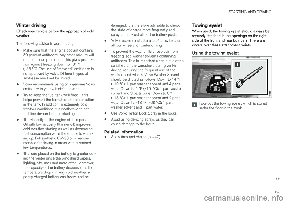
When used, the towing eyelet should always be securely attached in the openings on the rightside of the front and rear bumpers. There arecovers over these attachment points.
Using the towing eyelet
Take out the towing eyelet, which is stored under the floor in the trunk.
Page 374 of 548

STARTING AND DRIVING
372
Battery drain Your vehicle's electrical functions drain the bat- tery to varying extents.
Avoid using ignition mode II as much as posssi-
ble, or electrical functions that require a great deal of electrical current when the engine is notrunning. Using ignition mode I whenever possible con-
sumes less electrical current. Functions that require a great deal of electrical current include:
• the climate system blower
• headlights
• wipers
• infotainment system (especially at high vol-ume).
If the battery's charge level is low, a text messagewill appear in the instrument panel. The vehicle'senergy-saving function will then turn off orreduce certain functions that are currently con-suming electrical current. If the battery needs to be recharged, start the engine and let it idle for at least 15 minutes ordrive the vehicle (driving charges the batteryfaster than letting the engine idle).
Related information
• Ignition modes (p. 370)
Starting the engine
The engine can be started using the start knob on the tunnel console if there is a remote key inthe passenger compartment.
Start knob in the tunnel console between the front seats (generic illustration)
WARNING
Before starting the engine:
• Fasten the seat belt.
• Check that the seat, steering wheel and mirrors are adjusted properly.
• Make sure the brake pedal can bedepressed completely. Adjust the seat ifnecessary. To start the engine.
1. A remote key must be in the passenger com-
partment. On models with the standard Passive Start, the key has to be in the frontsection of the passenger compartment. If thevehicle is equipped the optional PassiveEntry system (keyless locking/unlocking) thekey can be anywhere in the vehicle.
2. Press firmly on the brake pedal 2
.
3. Turn the start knob toward START and
release it to start the engine.
> The starter motor will crank until the engine starts or its overheating protection is triggered.
2If the vehicle is moving, it is only necessary to turn the start knob toward START to start the engine.
Page 383 of 548
STARTING AND DRIVING
}}
* Option/accessory.381
Related information
•Conditions for Start/Stop (p. 381)
• Start/Stop (p. 379)
Conditions for Start/Stop
Certain conditions must be met for the Start/ Stop feature to function. If a condition is not met,this will be indicated in the instrument panel.
The engine does not auto-stopIn certain situations or conditions, the engine may not auto-stop when the vehicle comes to a
standstill, such as when:
• the vehicle has not reached a speed of approx. 8 mph (12 km/h) after starting.
• after several auto-stops, the speed mustagain exceed approx. 8 mph (12 km/h)before the next auto-stop.
• the driver's seat belt is unbuckled.
• the main battery's charge is below the mini-mum level.
• the engine has not reached its normal oper-ating temperature.
• the ambient temperature is below approx.23°F (-5°C) or above approx. 85°F (30°C).
• the windshield's heating function
* is acti-
vated.
• the climate system cannot keep the desiredsettings in the passenger compartment.
• the vehicle is backing up.
• the main battery's temperature is above orbelow the permitted limits.
• the driver is turning the steering wheel hard. •
the road's incline is very steep.
• the hood is opened.
• the transmission has not reached its normaloperating temperature.
• driving at high altitude and the engine hasnot reached its normal operating tempera-ture.
• the gear selector is in the manual shiftingposition.
• the ABS brakes have activated.
• hard braking (even if the ABS brakes havenot activated).
• many starts during a short time period havetriggered the starter motor's overheating pro-tection.
• a trailer's electrical system is connected tothe vehicle's electrical system.
The engine does not auto-startIn certain situations or conditions, the engine may not auto-start
after an auto-stop, such as:
• if the driver is not wearing a seat belt
• the gear selector is in the
P position and the
driver's door is open. The engine must be started normally.
The engine auto-starts while the brake pedal is depressed
In the following situations, the engine will auto-
start even though the brake pedal is depressed:
Page 384 of 548
||
STARTING AND DRIVING
382•
condensation forms on the inside of the win- dows.
• the climate system cannot keep the desiredsettings in the passenger compartment.
• electrical current consumption is temporarilyhigh or the main battery's charge is belowthe minimum level.
• the brake pedal is pumped repeatedly.
• the hood is opened.
• the vehicle begins to move or increasesspeed slightly (if the engine auto-stoppedbefore the vehicle was at a standstill).
• the driver's seat belt is unbuckled while the gear selector is in the
D or N positions.
• the gear selector is moved from
D to R or ±.
• the driver's door is opened with the gearselector in
D: an audible signal and a text
message will inform the driver that the igni- tion is on.
WARNING
Do not open the hood if the engine has auto- stopped. The engine could suddenly auto-start. Before opening the hood:
• Switch off the ignition by turning the start knob in the tunnel console toward
STOP.
• Be aware that if the engine has been run- ning, components in the engine compart-ment will be very hot.
Related information
• Using the Start/Stop function (p. 379)
Automatic transmission
The automatic transmission has 8 forward gears and shifts up or down based on the level ofacceleration, speed and engine speed (meas-ured in revolutions per minute - rpm). Manualshifting is also possible. The gear indicator in theinstrument panel shows the gear currently beingused or gear shift mode.
CAUTION
The transmission