steering wheel VOLVO S90 2020 Quick Guide
[x] Cancel search | Manufacturer: VOLVO, Model Year: 2020, Model line: S90, Model: VOLVO S90 2020Pages: 643, PDF Size: 13.68 MB
Page 7 of 643
5
SEATS AND STEERING WHEEL
Manual front seats182
Power * front seats
183
Adjusting the power * front seats
183
Storing positions for seats, mir- rors and head-up display *184
Using stored positions for seats,mirrors and head-up display *185
Front seat massage * settings
186
Adjusting front seat massage set-tings * 187
Adjusting * front seat cushion length
188
Adjusting front seat side bolstersettings * 189
Adjusting front seat lumbar support *
189
Adjusting the passenger seat fromthe driver's seat * 191
Adjusting the passenger seat from the rear seat 192
Steering wheel controls and horn 192
Adjusting the steering wheel 193
CLIMATE CONTROL
Climate 196
Climate zones 196
Climate control sensors 197
Perceived temperature 197
Climate control system voice commands 198
Air quality 199
Clean Zone *
199
Clean Zone Interior Package *
200
Interior Air Quality System *
200
Activating and deactivating the air quality sensor * 201
Passenger compartment air filter 201
Air distribution 201
Adjusting air distribution 202
Opening, closing and directing air vents 203
Air distribution options 204
Climate system controls 207
Activating and deactivating power front seats * 209
Activating and deactivating theheated front seat * 210
Activating and deactivating theheated rear seats * 210
Activating and deactivating frontseat ventilation * 211
Activating and deactivating the ventilated rear seats
* 212
Activating and deactivating theheated steering wheel *213
Activating and deactivating auto-matic steering wheel heating *213
Activating auto climate control 214
Activating and deactivating recir- culation 214
Activating and deactivating therecirculation timer setting 215
Activating and deactivating maxdefroster 215
Activating and deactivating theheated rear window and door mirrors 216
Automatically activating and deac-tivating the heated rear windowand door mirrors 217
Setting the blower speed for thefront seats 217
Setting the blower speed for the rear seats * 218
Setting the temperature for the front seats 220
Setting the temperature for the rear seats * 221
Synchronize temperature 222
Activating and deactivating air conditioning 223
Page 9 of 643
7
DRIVER SUPPORT
Driver support systems266
Speed-dependent steering wheel resistance 266
Electronic Stability Control 267
Electronic Stability Control insport mode 268
Activating or deactivating Sportmode for Electronic Stability Control 268
Electronic Stability Control sym-bols and messages 270
Distance Alert *
271
Activating or deactivating Dis-tance Alert 272
Distance Alert limitations 272
Cruise control 273
Selecting and activating cruise control 274
Deactivating cruise control 275
Cruise control standby mode 275
Adaptive Cruise Control *
276
Adaptive Cruise Control * controls
and display 277
Selecting and activating Adaptive Cruise Control * 278
Deactivating Adaptive Cruise Control *
279
Adaptive Cruise Control * standby
mode 280
Adaptive Cruise Control * limitations
281
Switching between cruise control and Adaptive Cruise Control * in
the center display 282
Symbols and messages for Adap-tive Cruise Control * 283
Pilot Assist *
285
Pilot Assist * controls and display
287
Selecting and activating Pilot Assist *
288
Deactivating Pilot Assist *
289
Pilot Assist * standby mode
290
Temporarily deactivating steeringassistance with Pilot Assist *291
Pilot Assist * limitations
291
Pilot Assist * symbols and messages
293
Collision risk warning from driver support 294
Switching target vehicles withdriver support 295
Adjusting set speed for driver support 296
Setting time interval to the vehicleahead 297
Auto-hold braking with driver support 298
Drive mode for driver support 299
Curve Speed Assist (CSA) *
300
Activating or deactivating Curve Speed Assist (CSA) * 301
Curve Speed Assist (CSA) * limitations
301
Passing assistance
302
Using passing assistance 302
Radar sensor 303
Radar sensor type approval 304
Camera 306
Camera/radar sensor limitations 307
Recommended camera and radar sensor maintenance 311
City Safety ™
312
City Safety sub-functions 313
Setting a warning distance forCity Safety 315
Detecting obstacles with City Safety 316
City Safety in crossing traffic 318
Limitations of City Safety in cross-ing traffic 319
City Safety steering assistance forevasive maneuver 320
City Safety steering assistancelimitations during evasive maneuvers 320
Automatic braking during delayedevasive maneuvers with City Safety 321
City Safety braking for oncomingvehicles 321
City Safety limitations 322
City Safety messages 325
Rear Collision Warning *
326
Page 11 of 643
9
STARTING AND DRIVING
Starting the vehicle378
Switching off the vehicle 380
Ignition modes 381
Selecting ignition mode 382
Brake functions 382
Brakes 383
Brake Assist System 384
Braking on wet roads 384
Braking on salted roads 385
Maintenance of the brake system 385
Parking brake 385
Activating and deactivating the parking brake 386
Settings for automatically activat-ing the parking brake 387
Parking on a hill 388
Parking brake malfunction 388
Auto-hold brakes 389
Activating and deactivating Auto-hold at a standstill 390
Hill Start Assist 390
Braking assist after a collision 391
Transmission 391
Automatic transmission 391
Gear selector positions for auto-matic transmissions 392
Using the steering wheel paddles
*
to shift 395
Shiftlock 397
Deactivating the automatic shiftlock 398
The kickdown function 398
All Wheel Drive (AWD) *
399
Drive modes *
399
Changing drive mode *
401
Eco drive mode 401
Activating and deactivating Eco drive mode using the function button 404
Start/Stop function 404
Driving with the Start/Stop function 404
Deactivating the Start/Stop function 406
Conditions for the Start/Stop function 406
Leveling control * and suspension
408
Leveling control settings *
411
Economical driving 411
Preparing for a long trip 412
Winter driving 412
Driving through standing water 413
Opening/closing the fuel filler door 414
Refueling 414
Fuel 415
Octane rating 416
Emission controls418
Overheating of engine and trans- mission 418
Battery drain 419
Jump starting using another battery 420
Towing using a towline 422
Attaching and removing the tow-ing eyelet 423
Recovery 425
HomeLink ®
* 425
Programming HomeLink ®
* 426
Using HomeLink ®
* 428
Type approval for HomeLink ®
* 429
Compass *
429
Activating and deactivating the compass * 430
Calibrating the compass *
430
Page 14 of 643
12
LOADING, STORAGE AND PASSENGER COMPARTMENT
Passenger compartment interior532
Tunnel console 533
Electrical outlets 534
Using the electrical outlets 534
Using the glove compartment 535
Sun visors 537
Folding down the armrest in the rear seat * 537
Cargo compartment 538
Loading recommendations 538
Roof loads and load carriers 539
Grocery bag holders 540
Load anchoring eyelets 540
Rear seat ski hatch *
540
MAINTENANCE AND SERVICE
Volvo's service program
542
Data transfer between vehicle and workshop over Wi-Fi 544
Download Center 545
Handling system updates viaDownload Center 545
Vehicle status 546
Scheduling service and repairs 547
Sending vehicle information to theworkshop 548
Hoisting the vehicle 549
Climate control system service 551
Replacing a windshield with head- up display * 551
Opening and closing the hood 552
Engine compartment overview 553
Engine oil 554
Checking and filling engine oil 555
Refilling coolant 556
Replacing bulbs 558
Removing the plastic cover to replace bulbs 559
Location of exterior lights 559
Replacing the low beam headlightbulbs 560
Replacing the high beam headlightbulbs 561
Replacing daytime running lights/ front parking light bulbs562
Replacing front turn signal bulbs 563
Replacing the rear fog light bulb 563
Bulb specifications 566
Start battery 567
Support battery 571
Battery symbols 572
Battery recycling 573
Fuses and fuseboxes 573
Replacing fuses 574
Fuses in the engine compartment 575
Fuses under the glove compartment 580
Fuses in the trunk 586
Cleaning the interior 591
Cleaning the center display 591
Cleaning the head-up display *
592
Cleaning fabric upholstery andceiling liner 593
Cleaning the seat belt 593
Cleaning floor mats and inlay mats 593
Cleaning leather upholstery *
594
Cleaning the leather steering wheel 595
Cleaning interior plastic, metal andwood surfaces 595
Page 33 of 643
YOUR VOLVO
}}
* Option/accessory.31
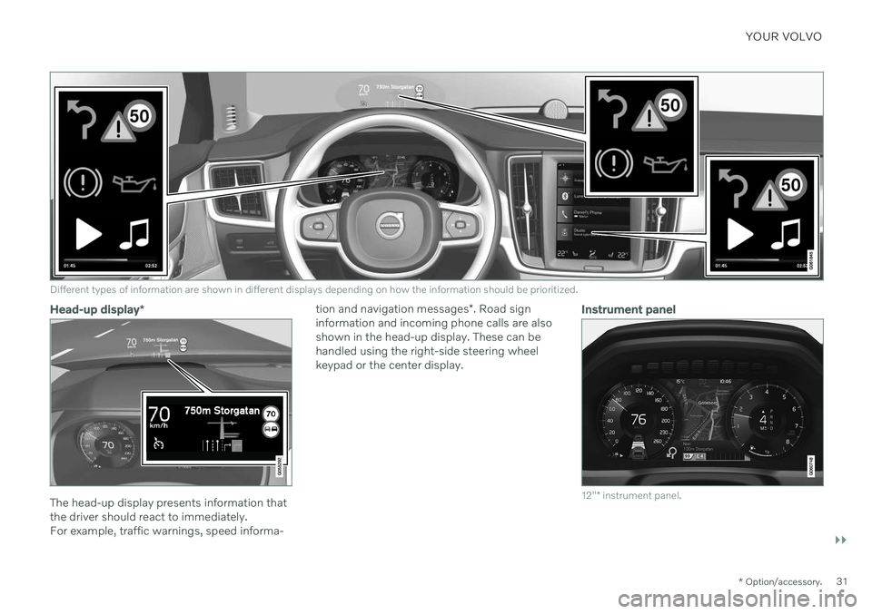
Different types of information are shown in different displays depending on how the information should be prioritized.
Head-up display*
The head-up display presents information that the driver should react to immediately.For example, traffic warnings, speed informa- tion and navigation messages
*. Road sign
information and incoming phone calls are alsoshown in the head-up display. These can behandled using the right-side steering wheelkeypad or the center display.
Instrument panel
12" * instrument panel.
Page 34 of 643
||
YOUR VOLVO
* Option/accessory.
32
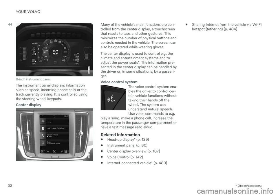
8-inch instrument panel.
The instrument panel displays information
such as speed, incoming phone calls or thetrack currently playing. It is controlled usingthe steering wheel keypads.
Center display
Many of the vehicle's main functions are con- trolled from the center display, a touchscreenthat reacts to taps and other gestures. Thisminimizes the number of physical buttons andcontrols needed in the vehicle. The screen canalso be operated while wearing gloves. The center display is used to control e.g. the climate and entertainment systems and to adjust the power seats *. The information pre-
sented in the center display can be handled by the driver or, in some situations, by a passen-ger.
Voice control system
The voice control system ena- bles the driver to control cer-tain vehicle functions withouttaking their hands off thewheel. The system canunderstand natural speech.Use voice commands to e.g.
play a song, make a phone call, increase thetemperature in the passenger compartment orhave a text message read aloud.
Related information
Head-up display
* (p. 139)
Instrument panel (p. 80)
Center display overview (p. 107)
Voice Control (p. 142)
Internet-connected vehicle
* (p. 480)
Sharing Internet from the vehicle via Wi-Fi hotspot (tethering) (p. 484)
Page 45 of 643

SAFETY
}}
* Option/accessory.43
Safety during pregnancy
It is important that seat belts are worn cor- rectly during pregnancy and that pregnantdrivers adjust their seating position accord-ingly.
Seat belt
The seat belt should fit closely against the shoulder, with the diagonal section betweenthe breasts and to the side of the stomach. The lap section of the seat belt should lie flat over the thighs and as far as possible underthe stomach. Never let it ride upward. Removeunnecessary slack and make sure the seat beltfits as close as possible to the body. Makesure there are no twists in the seat belt.
Seating positionAs pregnancy progresses, pregnant driversshould adjust the seat and steering wheel to a position that allows them to retain full controlof the vehicle (which means they should beable to easily reach the steering wheel andfoot pedals). Try to maintain as much distanceas possible between the stomach and thesteering wheel.
Related information
Safety (p. 42)
Seat belts (p. 47)
Manual front seats (p. 182)
Power
* front seats (p. 183)
Occupant safety
Safety is Volvo's cornerstone.
Volvo's concern for safetyOur concern for safety dates back to 1927 when the first Volvo rolled off the productionline. Three-point seat belts (a Volvo invention),safety cages, and energy-absorbing impactzones were designed into Volvo vehicles longbefore it was fashionable or required by gov-ernment regulation. We will not compromise our commitment to safety. We continue to seek out new safetyfeatures and to refine those already in ourvehicles. You can help. We would appreciatehearing your suggestions about improvingautomobile safety. We also want to know ifyou ever have a safety concern with your vehi-cle. Call us in the U.S. at: 1-800-458-1552 orin Canada at: 1-800-663-8255.
Page 53 of 643
SAFETY
}}
* Option/accessory.51
and improves the effect of other safety sys- tems such as the airbags. When a critical situation has passed, the seat belt and the electric seat belt tensioner arereset automatically. However, they can also bereset manually.
WARNING
Never attempt to alter or repair the seat belt on your own. Volvo recommends con-tacting an authorized Volvo workshop. If the seat belt has been exposed to extreme forces, e.g. in conjunction with acollision, the entire seat belt must bereplaced. Even if the seat belt appearsundamaged, some of its protective proper-ties may have been lost. Also replace theseat belt if it is worn or damaged. The newseat belt must be type approved andintended for the same seating position asthe replaced seat belt.
Related information
Seat belts (p. 47)
Buckling and unbuckling seat belts (p. 48)
Resetting the electric seat belt tensioners (p. 51)
City Safety
™ (p. 312)
Rear Collision Warning
* (p. 326)
Resetting the electric seat belt tensioners
The electric seat belt tensioners are designed to be reset automatically, but if the seat beltremains taut it can be reset manually.
1. Stop the vehicle in a safe location.
2. Unbuckle the seat belt and then rebuckle it.
> The seat belt and the electric seat belttensioner will be reset.
WARNING
Never attempt to alter or repair the seat belt on your own. Volvo recommends con-tacting an authorized Volvo workshop. If the seat belt has been exposed to extreme forces, e.g. in conjunction with acollision, the entire seat belt must bereplaced. Even if the seat belt appearsundamaged, some of its protective proper-ties may have been lost. Also replace theseat belt if it is worn or damaged. The newseat belt must be type approved andintended for the same seating position asthe replaced seat belt.
Related information
Seat belt tensioners (p. 50)
Seat belts (p. 47)
Door and seat belt reminders
This system is intended to remind occupants to buckle their seat belts and to alert thedriver if a door, hood or other opening (trunk,sunroof, etc.) is open.
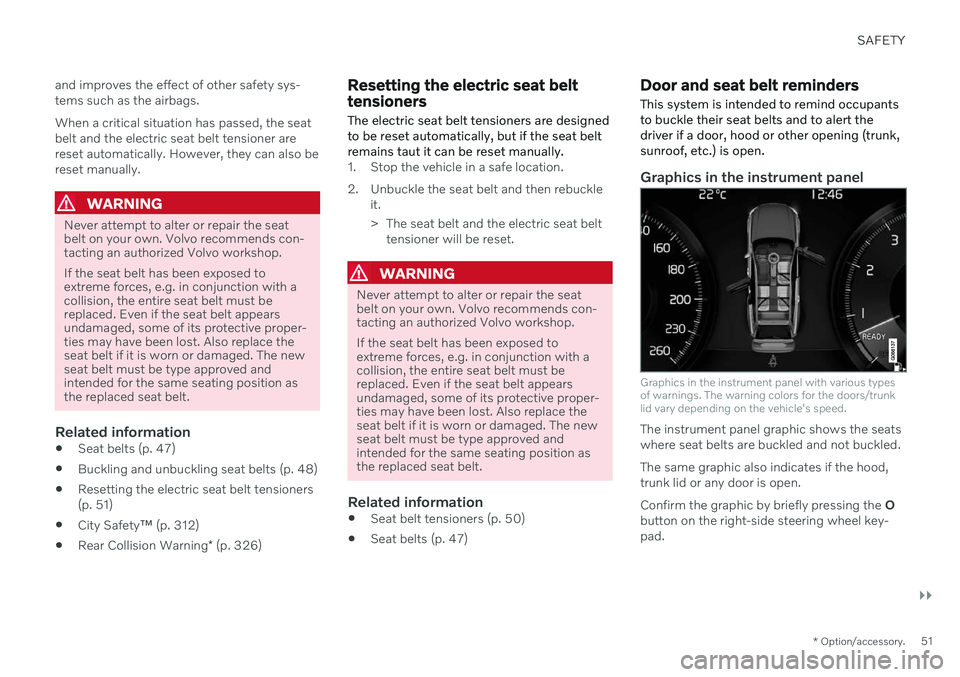
Graphics in the instrument panel
Graphics in the instrument panel with various types of warnings. The warning colors for the doors/trunklid vary depending on the vehicle's speed.
The instrument panel graphic shows the seats where seat belts are buckled and not buckled. The same graphic also indicates if the hood, trunk lid or any door is open. Confirm the graphic by briefly pressing the O
button on the right-side steering wheel key- pad.
Page 56 of 643

||
SAFETY
54
The front airbag systemThe front airbag system includes gas genera- tors surrounded by the airbags, and decelera-tion sensors that activate the gas generators,causing the airbags to be inflated with nitro-gen gas. As the movement of the seats' occupants compresses the airbags, some of the gas isexpelled at a controlled rate to provide bettercushioning. The belt tensioners minimize slackin the seat belts and are activated for occu-pants wearing their seat belts. The entire proc-ess, from inflation to deflation of the airbag,occurs within tenths of a second. The location of the front airbags is indicated by SRS AIRBAG embossed on the steering
wheel pad and above the glove compartment,and by decals on both sun visors and on thefront and far right side of the dash. The driver's side front airbag is folded and
located in the steering wheel hub.The knee airbag is folded on the underside of
the dashboard on the driver's side. The text AIRBAG is embossed on the panel.
The passenger's side front airbag is folded
behind a panel located above the glove com-partment.WARNING
The airbags in the vehicle are designed to be a SUPPLEMENT to-not areplacement for-the three-point seatbelts. For maximum protection, wearseat belts at all times. Be aware that nosystem can prevent all possible injuriesthat may occur in an accident.
Never drive with your hands on thesteering wheel pad/airbag housing.
The front airbags are designed to helpprevent serious injury. Deploymentoccurs very quickly and with considera-ble force. During normal deploymentand depending on variables such asseating position, one may experienceabrasions, bruises, swellings, or otherinjuries as a result of deployment ofone or both of the airbags.
When installing any accessory equip-ment, make sure that the front airbagsystem is not damaged. Any interfer-ence in the system could cause mal-function.
Front airbag deployment
The front airbags are designed to deployduring certain frontal or front-angular colli-sions, impacts, or decelerations, depend-ing on the crash severity, angle, speed andobject impacted. The airbags may also deploy in certain non-frontal collisionswhere rapid deceleration occurs.
The airbag system's sensors, which triggerthe front airbags, are designed to deter-mine if the collision is powerful enough toactivate the belt tensioners and/or the air-bags.
However, not all frontal collisions activate thefront airbags. If the collision involves a nonrigid object (e.g., a snow drift or bush), or a rigid, fixedobject at a low speed, the front airbagswill not necessarily deploy.
Front airbags do not normally deploy in aside impact collision, in a collision fromthe rear or in a rollover situation.
The amount of damage to the bodyworkdoes not reliably indicate if the airbagsshould have deployed or not.
Page 58 of 643
||
SAFETY
56
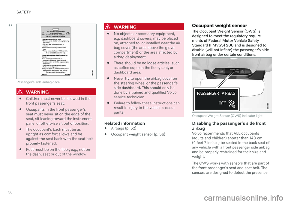
Passenger's side airbag decal.
WARNING
Children must never be allowed in the front passenger's seat.
Occupants in the front passenger'sseat must never sit on the edge of theseat, sit leaning toward the instrumentpanel or otherwise sit out of position.
The occupant's back must be asupright as comfort allows and beagainst the seat back with the seat beltproperly fastened.
Feet must be on the floor, e.g., not onthe dash, seat or out of the window.
WARNING
No objects or accessory equipment, e.g. dashboard covers, may be placedon, attached to, or installed near the airbag cover (the area above the glovecompartment) or the area affected byairbag deployment.
There should be no loose articles, suchas coffee cups on the floor, seat, ordashboard area.
Never try to open the airbag cover onthe steering wheel or the passenger'sside dashboard. This should only bedone by a trained and qualified Volvoservice technician.
Failure to follow these instructions canresult in injury to the vehicle's occu-pants.
Related information
Airbags (p. 52)
Occupant weight sensor (p. 56)
Occupant weight sensor
The Occupant Weight Sensor (OWS) is designed to meet the regulatory require-ments of Federal Motor Vehicle SafetyStandard (FMVSS) 208 and is designed todisable (will not inflate) the passenger's sidefront airbag under certain conditions.
Occupant Weight Sensor (OWS) indicator light
Disabling the passenger's side front airbag
Volvo recommends that ALL occupants (adults and children) shorter than 140 cm(4 feet 7 inches) be seated in the back seat ofany vehicle with a front passenger side airbagand be properly restrained for their size andweight. The OWS works with sensors that are part of the front passenger's seat and seat belt. Thesensors are designed to detect the presence