wheel bolts VOLVO S90 2020 Quick Guide
[x] Cancel search | Manufacturer: VOLVO, Model Year: 2020, Model line: S90, Model: VOLVO S90 2020Pages: 643, PDF Size: 13.68 MB
Page 13 of 643

11
Connecting the vehicle to the Internet via a phone (Wi-Fi)481
Connecting the vehicle to theInternet via vehicle modem (SIM card) 482
Vehicle modem settings 483
Sharing Internet from the vehiclevia Wi-Fi hotspot (tethering) 484
No or poor Internet connection 485
Deleting Wi-Fi networks 485
Wi-Fi technology and security 486
Terms of use and data sharing 486
Activating and deactivating datasharing 487
Data sharing for services 487
Hard disk storage space 488
License agreement for audio andmedia 489
WHEELS AND TIRES
Tires
500
Tire direction of rotation 502
Tread wear indicator 503
Tire terminology 503
Tire sidewall designations 504
Uniform Tire Quality Grading 506
Checking tire pressure 507
Adjusting tire pressure 508
Recommended tire pressure 509
Tire pressure monitoring system *
509
Saving a new inflation pressure in the monitoring system *511
Viewing tire pressure status in thecenter display * 512
Action when warned of low tire pressure 513
When changing wheels 514
Tool kit 514
Jack *
515
Wheel bolts 515
Removing a wheel 516
Installing a wheel 518
Spare wheel 519
Handling spare tires 520
Snow tires 521
Snow chains522
Tire sealing system 523
Using the tire sealing system 524
Inflate tires with the compressor included in the tire sealing system 527
Determining the vehicle's permit-ted weight 528
Page 516 of 643

WHEELS AND TIRES
* Option/accessory.
514
When changing wheels
The wheels can be changed, e.g. to switch to snow tires or spare tires. Follow the applica-ble instructions for removing and installingthe wheel.
Changing to tires of another dimension
Make sure that the tire dimension is approved for use on the vehicle.
Related information
Removing a wheel (p. 516)
Installing a wheel (p. 518)
Tool kit (p. 514)
Snow tires (p. 521)
Spare wheel (p. 519)
Wheel bolts (p. 515)
Tool kit
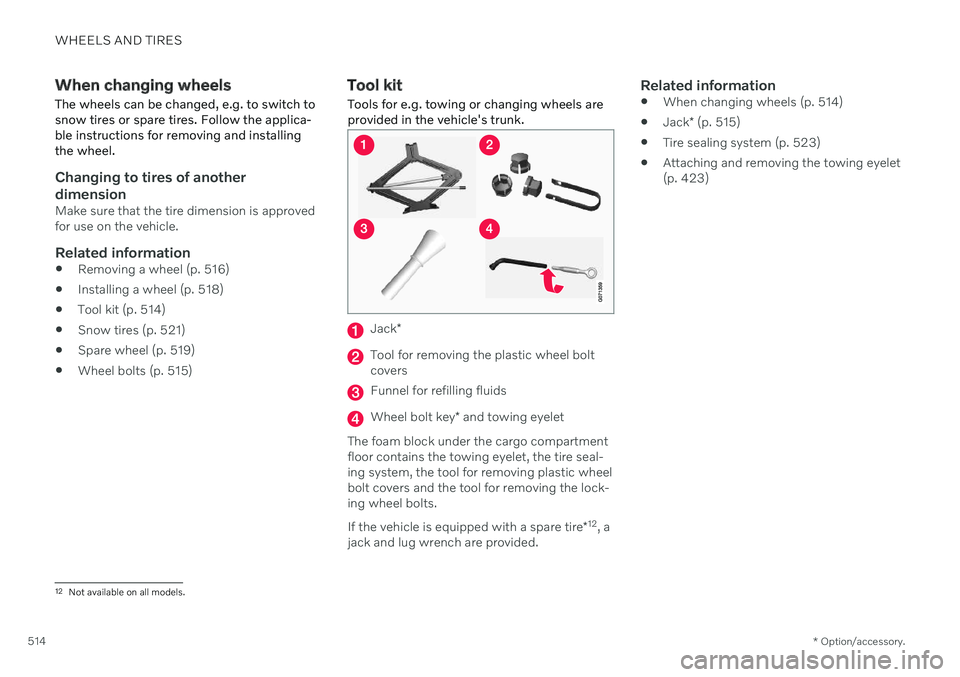
Tools for e.g. towing or changing wheels are provided in the vehicle's trunk.
Jack *
Tool for removing the plastic wheel bolt covers
Funnel for refilling fluids
Wheel bolt key * and towing eyelet
The foam block under the cargo compartment floor contains the towing eyelet, the tire seal-ing system, the tool for removing plastic wheelbolt covers and the tool for removing the lock-ing wheel bolts. If the vehicle is equipped with a spare tire *12
, a
jack and lug wrench are provided.
Related information
When changing wheels (p. 514)
Jack
* (p. 515)
Tire sealing system (p. 523)
Attaching and removing the towing eyelet (p. 423)
12
Not available on all models.
Page 517 of 643

WHEELS AND TIRES
* Option/accessory.515
Jack*
The jack can be used to lift the vehicle to e.g. change a wheel.CAUTION
When not in use, the jack
* should be
kept in its storage compartment under the cargo compartment floor.
The jack provided with your vehicle isintended to be used only in temporarysituations such as changing wheels inthe event of a flat tire. Only the jackthat came with your particular modelshould be used to lift the vehicle. If thevehicle needs to be lifted more fre-quently or for a prolonged period, usinga garage jack or hoist is recommended.Always follow this device's instructionsfor use.
The jack needs to be cranked together to the correct position in order to fit. For vehicles with
Leveling Control*
: If the
vehicle is equipped with the optional pneu- matic suspension, it must be turned off beforethe vehicle is lifted on a jack.
Related information
Tool kit (p. 514)
Hoisting the vehicle (p. 549)
Wheel bolts
The wheel bolts hold the wheel in place on the wheel hub.
Only use rims that have been tested and approved by Volvo and are included in Volvo'soriginal product range. Use a torque wrench to check that the wheel bolts are tightened correctly. Do not grease the wheel bolt threads.
WARNING
The wheel bolts may need to be tightened again several days after a wheel change.Temperature fluctuations and vibrationscan cause them to loosen slightly.
CAUTION
The wheel bolts should be tightened to 140 Nm (103 ft. lbs.). Over-tightening orunder-tightening could damage the threa-ded joints.
Locking wheel bolts *A tool for removing the locking wheel bolts is located in the foam block under the cargocompartment floor.
Related information
Removing a wheel (p. 516)
Installing a wheel (p. 518)
Page 518 of 643

WHEELS AND TIRES
* Option/accessory.
516
Removing a wheel Wheel changes must always be carried out correctly. The following instructions showhow to remove a wheel and what is impor-tant to keep in mind.
CAUTION
When not in use, the jack
* should be
kept in its storage compartment under the cargo compartment floor.
The jack provided with your vehicle isintended to be used only in temporarysituations such as changing wheels inthe event of a flat tire. Only the jackthat came with your particular modelshould be used to lift the vehicle. If thevehicle needs to be lifted more fre-quently or for a prolonged period, usinga garage jack or hoist is recommended.Always follow this device's instructionsfor use.
WARNING
Apply the parking brake and put the gear selector in the Park (
P) position.
Block the wheels standing on theground, use rigid wooden blocks orlarge stones.
Check that the jack is not damaged,the threads are properly lubricated andit is free from dirt.
Be sure the jack is on a firm, level, non-slippery surface and that it is uprightand not leaning.
The jack must correctly engage in thejack attachment.
No objects should be placed betweenthe base of the jack and the ground, orbetween the jack and the attachmentbar on the vehicle.
Never let anyone remain in the vehiclewhen it is raised on a jack.
If a tire must be changed near passingtraffic, make sure all passengers moveto a safe location.
Use a jack intended for the vehiclewhen changing a tire. For any otherjob, use stands to support the vehicle.
Never crawl under or allow any part ofyour body to be extended under a vehi-cle supported by a jack. 1. Turn on the vehicle's hazard warning
flashers if a wheel change must be per-formed in an area with traffic.
2. Apply the parking brake and put the gear selector in P, or first gear if the vehicle has
a manual transmission. For vehicles with
Leveling Control* : If the
vehicle is equipped with pneumatic sus- pension, this must be switched off before the vehicle is lifted with the jack *.
3. Take out the jack *, lug wrench * and tool for
removing the plastic covers, which are stowed in the foam block.
Tool for removing the plastic covers on the wheel bolts.
4. Place chocks in front of and behind the wheels that are still on the ground. For example, use heavy wooden blocks orlarge stones.
Page 519 of 643

WHEELS AND TIRES
* Option/accessory.517
5. Using the lug wrench, screw the towing
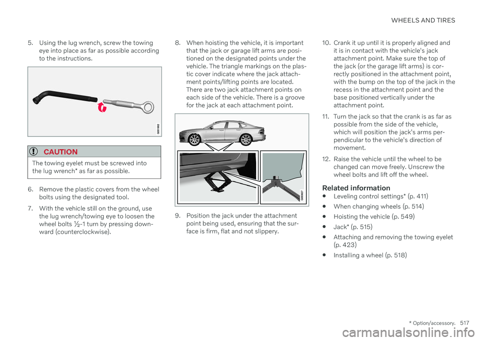
eye into place as far as possible according to the instructions.
CAUTION
The towing eyelet must be screwed into the lug wrench * as far as possible.
6. Remove the plastic covers from the wheel
bolts using the designated tool.
7. With the vehicle still on the ground, use the lug wrench/towing eye to loosen the wheel bolts ½-1 turn by pressing down-ward (counterclockwise). 8. When hoisting the vehicle, it is important
that the jack or garage lift arms are posi-tioned on the designated points under thevehicle. The triangle markings on the plas-tic cover indicate where the jack attach-ment points/lifting points are located.There are two jack attachment points oneach side of the vehicle. There is a groovefor the jack at each attachment point.
9. Position the jack under the attachmentpoint being used, ensuring that the sur- face is firm, flat and not slippery. 10. Crank it up until it is properly aligned and
it is in contact with the vehicle's jackattachment point. Make sure the top ofthe jack (or the garage lift arms) is cor-rectly positioned in the attachment point,with the bump on the top of the jack in therecess in the attachment point and thebase positioned vertically under theattachment point.
11. Turn the jack so that the crank is as far as possible from the side of the vehicle,which will position the jack's arms per-pendicular to the vehicle's direction ofmovement.
12. Raise the vehicle until the wheel to be changed can move freely. Unscrew thewheel bolts and lift off the wheel.
Related information
Leveling control settings
* (p. 411)
When changing wheels (p. 514)
Hoisting the vehicle (p. 549)
Jack
* (p. 515)
Attaching and removing the towing eyelet(p. 423)
Installing a wheel (p. 518)
Page 520 of 643

WHEELS AND TIRES
* Option/accessory.
518
Installing a wheel Wheel changes must always be carried out correctly. The following instructions showhow to install a wheel and what is importantto keep in mind.
CAUTION
When not in use, the jack
* should be
kept in its storage compartment under the cargo compartment floor.
The jack provided with your vehicle isintended to be used only in temporarysituations such as changing wheels inthe event of a flat tire. Only the jackthat came with your particular modelshould be used to lift the vehicle. If thevehicle needs to be lifted more fre-quently or for a prolonged period, usinga garage jack or hoist is recommended.Always follow this device's instructionsfor use.
WARNING
Apply the parking brake and put the gear selector in the Park (
P) position.
Block the wheels standing on theground, use rigid wooden blocks orlarge stones.
Check that the jack is not damaged,the threads are properly lubricated andit is free from dirt.
Be sure the jack is on a firm, level, non-slippery surface and that it is uprightand not leaning.
The jack must correctly engage in thejack attachment.
No objects should be placed betweenthe base of the jack and the ground, orbetween the jack and the attachmentbar on the vehicle.
Never let anyone remain in the vehiclewhen it is raised on a jack.
If a tire must be changed near passingtraffic, make sure all passengers moveto a safe location.
Use a jack intended for the vehiclewhen changing a tire. For any otherjob, use stands to support the vehicle.
Never crawl under or allow any part of your body to be extended under a vehi-cle supported by a jack.
The vehicle must be raised high enough sothat the wheel you are removing can turnfreely.
1. Clean the contact surfaces between the wheel and the wheel hub.
2. Lift the wheel into place. Tighten the wheel bolts securely.Do not grease the wheel bolt threads.
3. Lower the vehicle so that the wheel can- not rotate.
Page 521 of 643

WHEELS AND TIRES
}}
* Option/accessory.519
4. Tighten the wheel bolts in a crisscross pat-
tern (as shown in illustration). It is impor- tant that the wheel bolts are securelytightened. Tighten to 140 Nm (103 ft. lbs.).Use a torque wrench to check torque.
5. Press the plastic covers onto the wheelbolts.
6. Check the tire inflation pressure and store the new inflation pressure in the tire pres- sure monitoring system *.
WARNING
The wheel bolts may need to be tightened again several days after a wheel change.Temperature fluctuations and vibrationscan cause them to loosen slightly.
NOTE
After inflating a tire, always replace the valve cap to help prevent valve damagecaused by gravel, dirt, etc.
Use plastic valve caps only. Metal capscould corrode and become difficult toremove.
Related information
When changing wheels (p. 514)
Hoisting the vehicle (p. 549)
Jack
* (p. 515)
Tool kit (p. 514)
Removing a wheel (p. 516)
Saving a new inflation pressure in the monitoring system
* (p. 511)
Checking tire pressure (p. 507)
Spare wheel 13
The spare wheel is a Temporary Spare and can be used to temporarily replace a punc- tured tire on one of the vehicle's regularwheels.
The spare tire is only intended for temporary use. Replace it with a normal wheel as soon aspossible. The driving characteristics of the vehicle change and ground clearance reduces whenthe spare wheel is used. Do not wash the vehi-cle in an automatic car wash while using theTemporary Spare. The recommended tire pressure must be maintained regardless of at which position thetemporary spare wheel is used on the vehicle. If the spare wheel is damaged, a new one can be purchased from a Volvo retailer.
WARNING
Current legislation prohibits the use of the "Temporary Spare" tire other than as atemporary replacement for a puncturedtire. It must be replaced as soon as possi-ble by a standard tire. Road holding andhandling may be affected with the "Tempo-rary Spare" in use. Do not drive faster than80 km/h (50 mph).
13 Not available on all models.
Page 632 of 643

INDEX
630emergency brake lights 157
front fog lights 155
Hazard warning flashers 157
high beams 152, 153
home safe lighting 158
in passenger compartment 158
light locations 559
low beams 151
position lights 150
rear fog light 156
settings 149
Turn signals 154
Lighting, replacing bulbs 558 daytime running lights/front parking
lights 562
front turn signals 563
high beams 561
light bulbs, specifications 566
low beams 560
rear fog light 563
remove plastic cover 559
Limp home 391 Load anchoring eyelets cargo compartment 540
Load anchoring hooks 540
Load carriers 539
Load index 504
Loading general 538
load anchoring eyelets 540
long load 539
Lock indication 232 setting 233
Locking/unlocking trunk lid 251
Locking wheel bolts 515 Locks locking/unlocking 236
Low battery charge level start battery 419
Low beams 151
Low oil level 555
M
Maintained climate comfort 227 start/stop 228
Maintenance 542 corrosion protection 602
Max. axle weight 615
Max. roof load 615
Media player 455, 456, 457 compatible file formats 463
voice control 145
Messages and symbols Adaptive Cruise Control 283
Assistance at risk of collision 354
BLIS 330
City Safety 325
Cross Traffic Alert 334
Lane Keeping Aid 346
Park Assist Camera 367
Park Assist Pilot 375
Parking Assist 359
Pilot Assist 293
stability and traction control system 270
Messages in display 103, 137 handling 104, 137
saved 105, 138
Mileage 85 Misting condensation in headlights 596, 599
Mood lighting 159 adjusting 160
O
Occupant safety 43
Occupant weight sensor 56
Page 638 of 643

INDEX
636Type approval
HomeLink ® 429
radar system 304
U
Uniform Tire Quality Grading 506
Units 129Unlocking settings 237
with key blade 245
USB socket for connecting media 462
V
Vehicle care 596, 597, 599, 600, 601,
602
leather upholstery 594
Vehicle Event Data 33 Vehicle functions in the center display 119
Vehicle key bat. low 238 Vehicle modem connecting vehicle to Internet 482
settings 483
Vehicle recovery 425
Vehicle status 546
inflation pressure 512
Vehicle upholstery 591, 593, 594, 595
Vehicle weight 615
Ventilation 201, 202, 203 Seats 211, 212
Video 460, 462 settings 461
Voice control 142 climate 198
phone 145
radio and media 145
settings 146
VOL mark 500
Volvo ID 26 create and register 27
W
Warning lightsAdaptive Cruise Control 294
airbags SRS 93
alternator does not charge 93
brake system error 93
low oil pressure 93
parking brake applied 93
Pilot Assist 294
seat belt reminder 93
stability and traction control system 267
starter battery not charging 93
system error 93
WARNING 93
Warning sound parking brake 388
warning symbols 93 Warning symbols safety 42
Warranties 542Washer Headlights 178
washer fluid, filling 607
Windshield 178
Washer fluid 176, 607
Washer nozzles, heated 176
Waxing 596Weights Curb weight 615
Wheel bolts 515 Wheels cleaning 602
mounting 518
removal 516
Snow chains 522