VOLVO S90 T8 2018 Owner´s Manual
Manufacturer: VOLVO, Model Year: 2018, Model line: S90 T8, Model: VOLVO S90 T8 2018Pages: 166, PDF Size: 4.72 MB
Page 111 of 166
PRACTICAL INFORMATION
}}}}
109
NOTE
•The tire sealing system is only intended to seal holes on the tire
Page 112 of 166
||
PRACTICAL INFORMATION
110
•Ingestion: Do
NOT induce vomiting
unless directed to do so by medical per- sonnel. Get medical attention.
• Disposal: Dispose of this material and itscontainer to a hazardous or special wastecollection point.
Related information
•Inflating a tire with the tire sealing systemcompressor (p. 114)
• Using the tire sealing system (p. 110)
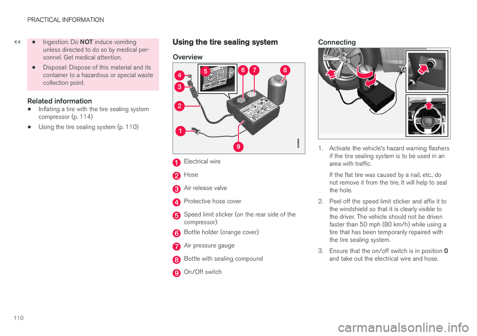
Using the tire sealing system
Overview
Electrical wire
Hose
Air release valve
Protective hose cover
Speed limit sticker (on the rear side of the compressor)
Bottle holder (orange cover)
Air pressure gauge
Bottle with sealing compound
On/Off switch
Connecting
1. Activate the vehicle's hazard warning flashers
if the tire sealing system is to be used in an area with traffic. If the flat tire was caused by a nail, etc., do not remove it from the tire. It will help to sealthe hole.
2. Peel off the speed limit sticker and affix it to the windshield so that it is clearly visible tothe driver. The vehicle should not be drivenfaster than 50 mph (80 km/h) while using atire that has been temporarily repaired withthe tire sealing system.
3. Ensure that the on/off switch is in position 0
and take out the electrical wire and hose.
Page 113 of 166
PRACTICAL INFORMATION
}}
111
NOTE
Do not break the seal on the bottle. This occurs automatically when the bottle isscrewed into the holder.
WARNING
Contact with the sealing compound may cause skin irritation. If contact occurs, washthe affected area immediately with soap andwater.
4. Unscrew the orange cover over the bottle holder on the compressor and unscrew the cap on the bottle of sealing compound.
5. Screw the bottle into the bottle holder as far as possible.
WARNING
The bottle is equipped with a catch to keep it securely in place and help prevent sealingcompound leakage. Once in place, the bottlecannot be unscrewed. This must be done by atrained and qualified Volvo service technician. 6. Be sure the air release valve on the com-
pressor's hose is completely closed. Remove the valve cap from the tire
Page 114 of 166
||
PRACTICAL INFORMATION
1129. Pump the tire for 7 minutes.
CAUTION
The compressor should not be used for more than 10 minutes at a time to avoid overheat-ing.
10. Switch off the compressor and check the
inflation pressure on the air pressure gauge. Inflation pressure should be between22—51 psi (1.8—3.5 bar). Use the airrelease valve to release some air from thetire if necessary.
WARNING
If the pressure remains below 22 psi (1.8 bar) after approximately seven minutes, turn offthe compressor. In this case, the hole is toolarge to be sealed and the vehicle should notbe driven.
11. Switch off the compressor and disconnect the electrical wire from the 12-volt socket.
12. Unscrew the hose from the tire's inflation valve and put the cover on the hose back into place to help prevent seepage of residualsealing compound from the hose. 13. Reinstall the valve cap.
CAUTION
•
After inflating the tires, always reinstall the valve cap to help avoid damage to thevalve from dirt, gravel, etc.
• Use plastic valve caps only. Metal capscould corrode and become difficult toremove.
14. Immediately drive the vehicle for approxi-
mately 2 miles (3 km) at a maximum speed of 50 mph (80 km/h) to distribute the seal-ing compound in the tire. During the tire'sfirst revolution, some sealing compound mayspray out of the puncture hole.
WARNING
No one should stand closer to the vehicle than approx. 7 ft (2 m) when it drives away tohelp avoid being sprayed with sealing com-pound.
CAUTION
If your vehicle is equipped with the Tire Pres- sure Monitoring System (TPMS), the use ofthe sealing compound may lead to incorrecttire pressure readings or in rare cases, dam-age to the tire pressure sensor. Use the tiresealing system to check and adjust the dam-aged tire's inflation pressure.
NOTE
•Safely stow the tire sealing system in a convenient place as it will soon be usedagain to check the tire
Page 115 of 166
PRACTICAL INFORMATION
}}
113
ice technician to have the bottle removed and properly disposed of.
WARNING
If heavy vibrations, unsteady steering behavior, or noises should occur while driving, reducespeed and park the vehicle in a safe place.Recheck the tire for bumps, cracks, or othervisible damage, and recheck its inflation pres-sure. If the pressure is below 19 psi (1.3 bar),do not continue driving. Have the vehicletowed to a trained and qualified Volvo servicetechnician.
15. Rechecking the pressure Reconnect the tire sealing system's hose to the tire's inflation valve. 16. Without starting the compressor, check the
inflation pressure on the air pressure gauge. •If the pressure is under 19 psi (1.3 bar), the puncture has not been sealed suffi-ciently and the vehicle should not bedriven. Have the vehicle towed to a trainedand qualified Volvo service technician.
• If the pressure is more than 19 psi(1.3 bar), connect the electrical wire to a12-volt socket, start the compressor andinflate the tire to the correct pressure(see the tire pressure decal on the on thedriver's side B-pillar (the structural mem-ber at the side of the vehicle, at the rearof the driver's door opening). Use the airrelease valve to release some air from thetire if necessary.
17. Switch off the compressor and disconnect the electrical wire from the 12-volt socket.Unscrew the hose from the tire
Page 116 of 166
||
PRACTICAL INFORMATION
114
WARNING
•After using the tire sealing system, the vehicle should not be driven farther thanapproximately 120 miles (200 km).
• Have the tire inspected by a trained andqualified Volvo service technician as soonas possible to determine if it can be per-manently repaired or must be replaced.
• The vehicle should not be driven fasterthan 50 mph (80 km/h) while using a tirethat has been temporarily repaired withthe tire sealing system.
• After using the tire sealing system, drivecarefully and avoid abrupt steeringmaneuvers and sudden stops.
Related information
• Tire sealing system (p. 108)
• Checking tire inflation pressure (p. 97)
• Volvo Roadside Assistance (p. 6)
Inflating a tire with the tire sealing system compressor
The compressor can be used to inflate a tire.
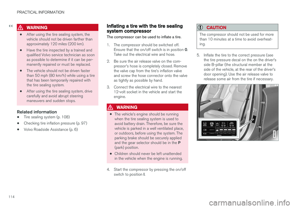
1. The compressor should be switched off. Ensure that the on/off switch is in position 0.
Take out the electrical wire and hose.
2. Be sure the air release valve on the com- pressor's hose is completely closed. Remove the valve cap from the tire
Page 117 of 166
PRACTICAL INFORMATION
}}
* Option/accessory.115
6. Turn off the compressor (press the on/off
switch to position 0) when the correct infla-
tion pressure has been reached.
CAUTION
• After inflating the tires, always reinstall the valve cap to help avoid damage to thevalve from dirt, gravel, etc.
• Use plastic valve caps only. Metal capscould corrode and become difficult toremove.
7. Disconnect the electrical wire from the 12-
volt socket.
Related information
• Checking tire inflation pressure (p. 97)
• Tire sealing system (p. 108)
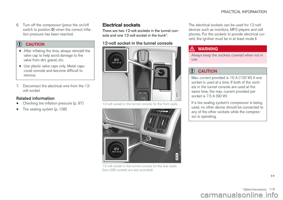
Electrical sockets There are two 12-volt sockets in the tunnel con- sole and one 12-volt socket in the trunk
*.
12-volt socket in the tunnel console
12-volt socket in the tunnel console for the front seats
12-volt socket in the tunnel console for the rear seats (two USB sockets are also provided)
The electrical sockets can be used for 12-volt devices such as monitors, MP3 players and cellphones. For the sockets to provide electrical cur- rent, the ignition must be in at least mode I.
WARNING
Always keep the sockets covered when not in use.
CAUTION
Max. current provided is 10 A (120 W) if one socket is used at a time. If both of the sock-ets in the tunnel console are used at thesame time, the max. current provided persocket is 7.5 A (90 W) If a tire sealing system's compressor is being used, no other device should be connected toany of the other sockets while the compres-sor is operating.
Page 118 of 166
||
PRACTICAL INFORMATION
116
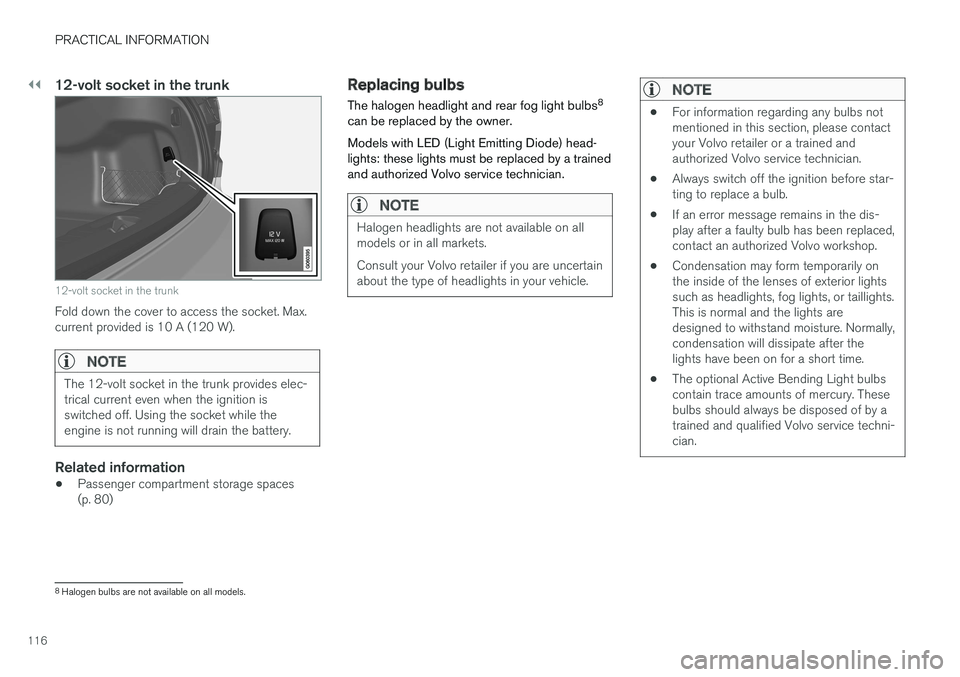
12-volt socket in the trunk
12-volt socket in the trunk
Fold down the cover to access the socket. Max. current provided is 10 A (120 W).
NOTE
The 12-volt socket in the trunk provides elec- trical current even when the ignition isswitched off. Using the socket while theengine is not running will drain the battery.
Related information
•Passenger compartment storage spaces (p. 80)
Replacing bulbs
The halogen headlight and rear fog light bulbs 8
can be replaced by the owner. Models with LED (Light Emitting Diode) head- lights: these lights must be replaced by a trainedand authorized Volvo service technician.
NOTE
Halogen headlights are not available on all models or in all markets. Consult your Volvo retailer if you are uncertain about the type of headlights in your vehicle.
NOTE
• For information regarding any bulbs not mentioned in this section, please contactyour Volvo retailer or a trained andauthorized Volvo service technician.
• Always switch off the ignition before star-ting to replace a bulb.
• If an error message remains in the dis-play after a faulty bulb has been replaced,contact an authorized Volvo workshop.
• Condensation may form temporarily onthe inside of the lenses of exterior lightssuch as headlights, fog lights, or taillights.This is normal and the lights aredesigned to withstand moisture. Normally,condensation will dissipate after thelights have been on for a short time.
• The optional Active Bending Light bulbscontain trace amounts of mercury. Thesebulbs should always be disposed of by atrained and qualified Volvo service techni-cian.
8
Halogen bulbs are not available on all models.
Page 119 of 166
PRACTICAL INFORMATION
}}
* Option/accessory.117
CAUTION
Never touch the glass of bulbs with your fin- gers. Grease and oils from your fingers vapor-ize in the heat and will leave a deposit on thereflector, which will damage it.
WARNING
•The ignition should be switched off com- pletely (be in ignition mode
0) when
replacing bulbs.
• If the engine has been running just prior to replacing bulbs in the headlight hous-ing, please keep in mind that componentsin the engine compartment will be hot.
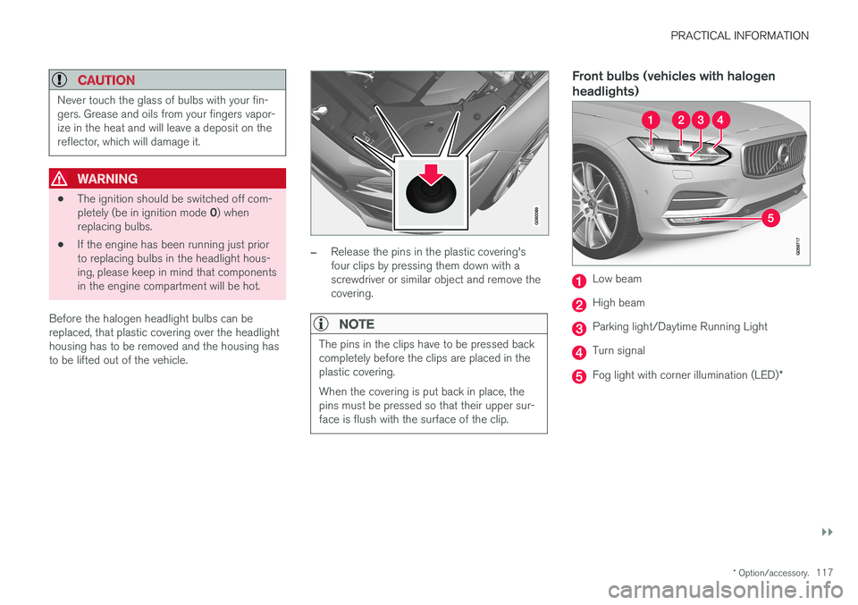
Before the halogen headlight bulbs can bereplaced, that plastic covering over the headlighthousing has to be removed and the housing hasto be lifted out of the vehicle.
–Release the pins in the plastic covering's four clips by pressing them down with ascrewdriver or similar object and remove thecovering.
NOTE
The pins in the clips have to be pressed back completely before the clips are placed in theplastic covering. When the covering is put back in place, the pins must be pressed so that their upper sur-face is flush with the surface of the clip.
Front bulbs (vehicles with halogen headlights)
Low beam
High beam
Parking light/Daytime Running Light
Turn signal
Fog light with corner illumination (LED) *
Page 120 of 166
||
PRACTICAL INFORMATION
118
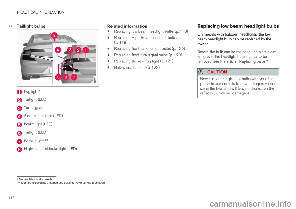
Taillight bulbs
Fog light9
Taillight (LED)
Turn signal
Side marker light (LED)
Brake light (LED)
Taillight (LED)
Backup light
10
High-mounted brake light (LED)
Related information
•
Replacing low beam headlight bulbs (p. 118)
• Replacing High Beam headlight bulbs (p. 119)
• Replacing front parking light bulbs (p. 120)
• Replacing front turn signal bulbs (p. 120)
• Replacing the rear fog light (p. 121)
• Bulb specifications (p. 123)
Replacing low beam headlight bulbs
On models with halogen headlights, the low beam headlight bulb can be replaced by theowner.
Before the bulb can be replaced, the plastic cov- ering over the headlight housing has to beremoved, see the article "Replacing bulbs."
CAUTION
Never touch the glass of bulbs with your fin- gers. Grease and oils from your fingers vapor-ize in the heat and will leave a deposit on thereflector, which will damage it.
9 Not available in all markets.
10 Must be replaced by a trained and qualified Volvo service technician.