park VOLVO V60 2013 Workshop Manual
[x] Cancel search | Manufacturer: VOLVO, Model Year: 2013, Model line: V60, Model: VOLVO V60 2013Pages: 422, PDF Size: 9.59 MB
Page 301 of 422
07 During your journey
Driving with a trailer
07
299
Diesel engine 5-cyl
•In the event of a risk of overheating the
optimal speed for the engine is 2300-3000
rpm for optimal circulation of the coolant.
Automatic gearbox
OverheatingWhen driving with a trailer in hilly terrain in a hot
climate there may be a risk of overheating.
•An automatic gearbox selects the optimum
gear related to load and engine speed.
•In the event of overheating a warning sym-
bol illuminates on the instrument panel
combined with a text message - follow the
recommendation given.
Steep inclines
•Do not lock the automatic transmission in
a higher gear than the engine "can cope
with" - it is not always a good idea to drive
at a high gear with low engine revolutions.
IMPORTANT
See also the specific information on slow
driving with trailer for cars with the
Powershift automatic transmission on page
125.
Parking on a hill1. Depress the foot brake.2. Activate the parking brake.
3.
Move the gear selector to position P.
4. Release the foot brake.
•Move the gear selector to park position P
when parking an automatic car with a
hitched trailer. Always use the parking
brake.
•Block the wheels with chocks when park-
ing a car with hitched trailer on a hill.
Starting on a hill1. Depress the foot brake.
2. Move the gear selector to driving posi-
tion D.
3. Release the parking brake.
4. Release the foot brake and start driving off.
Towing bracket
If the car is equipped with a detachable towbar,
the installation instructions for the loose sec-
tion must be followed carefully, see page 301.
WARNING
If the car is fitted with a Volvo detachable
towbar:
•Follow the installation instructions care-
fully.
•The detachable section must be locked
with the key before setting off.
•Check that the indicator window shows
green.
Important checks
•The towbar's towball must be cleaned and
greased regularly.
NOTE
If a towball hitch with vibration damper is
used, it is not necessary to grease the tow-
ball.
ProCarManuals.com
Page 306 of 422
07 During your journey
Towing and recovery
07
304
Towing
Find out the statutory maximum speed limit for
towing before towing begins.
1. Unlock the steering lock by inserting the
remote control key in the ignition switch
and giving a long press on the START/
STOP ENGINE button - key position II is
activated, see page 78 for more informa-
tion on key positions.
2. The remote control key must remain in the
ignition switch while the car is being towed.
3. Keep the towline taut when the towing
vehicle reduces speed by holding your foot
gently pressed on the brake pedal -
thereby avoiding unnecessary jerking.
4. Be prepared to brake to stop.
WARNING
•Check that the steering lock is unlocked
before towing.
•The remote control key must be in key
position II - in position I all airbags are
deactivated.
•Never remove the remote control key
from the ignition switch when the car is
being towed.
WARNING
The brake servo and power steering do not
work when the engine is switched off - the
brake pedal needs to be depressed
about 5 times more heavily and the steering
is considerably heavier than normal.
Manual gearboxPrior to towing:
–Move gear lever into neutral and release
the parking brake.
Automatic gearbox Geartronic
IMPORTANT
Note that the car must always be towed with
the wheels rolling forward.
•Cars with automatic gearbox must not
be towed at speeds above 80 km/h or
further than 80 km.
Prior to towing:
–
Move the gear selector to position N and
release the parking brake.
Automatic gearbox PowershiftThe model with Powershift transmission
should not be towed as it is dependent on the
engine running in order to receive sufficientlubrication. If towing still has to take place, the
route must be as short as possible and then
with very low speed.
In the event of uncertainty as to whether or not
the car is equipped with Powershift transmis-
sion, this can be verified by checking the des-
ignation on the transmission's label under the
bonnet - see page 370. The designa-
tion ”MPS6” means that it is Powershift – trans-
mission otherwise it is Geartronic automatic
transmission.
IMPORTANT
Avoid towing.
•However, the car can be towed for a
short distance at low speed to move it
from a dangerous position - not further
than 10 km and not faster than
10 km/h. Note that the car must always
be towed with the wheels rolling for-
ward.
•In the event of moving a longer distance
than 10 km, the car must be transported
with the drive wheels raised from the
road - professional recovery is recom-
mended.
Prior to towing:
–
Move the gear selector to position N and
release the parking brake.
ProCarManuals.com
Page 317 of 422
08 Wheels and tyres
Changing wheels
08
* Option/accessory, for more information, see Introduction.315 Removing
Set up the warning triangle, see page 318 if a
wheel must be replaced at a busy location. The
car and jack* must be on a firm horizontal sur-
face.
1. Apply the parking brake and engage
reverse gear, or position P if the car has an
automatic gearbox.
WARNING
Check that the jack is not damaged, that the
threads are thoroughly lubricated and that it
is free from dirt.
NOTE
Volvo recommends only using the jack* that
belongs to the car model in question, which
is indicated on the jack's label.
The label also indicates the jack's maximum
lift capacity at a specified minimum lifting
height.
2. Take out the jack*, wheel wrench* and
removal tool for wheel covers* located
under the cargo floor in the cargo area. If
another jack is selected, see page 328.
3. Place chocks in front of and behind the
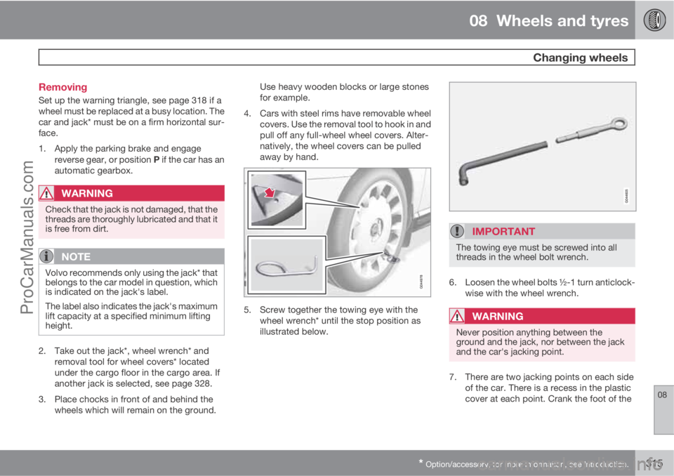
wheels which will remain on the ground.Use heavy wooden blocks or large stones
for example.
4. Cars with steel rims have removable wheel
covers. Use the removal tool to hook in and
pull off any full-wheel wheel covers. Alter-
natively, the wheel covers can be pulled
away by hand.
5. Screw together the towing eye with the
wheel wrench* until the stop position as
illustrated below.
IMPORTANT
The towing eye must be screwed into all
threads in the wheel bolt wrench.
6. Loosen the wheel bolts ½-1 turn anticlock-
wise with the wheel wrench.
WARNING
Never position anything between the
ground and the jack, nor between the jack
and the car's jacking point.
7. There are two jacking points on each side
of the car. There is a recess in the plastic
cover at each point. Crank the foot of the
ProCarManuals.com
Page 318 of 422
08 Wheels and tyres
Changing wheels
08
316
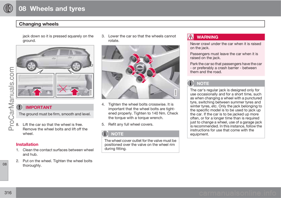
jack down so it is pressed squarely on the
ground.
IMPORTANT
The ground must be firm, smooth and level.
8. Lift the car so that the wheel is free.
Remove the wheel bolts and lift off the
wheel.
Installation
1. Clean the contact surfaces between wheel
and hub.
2. Put on the wheel. Tighten the wheel bolts
thoroughly.3. Lower the car so that the wheels cannot
rotate.
4. Tighten the wheel bolts crosswise. It is
important that the wheel bolts are tight-
ened properly. Tighten to 140 Nm. Check
the torque with a torque wrench.
5. Refit any full wheel covers.
NOTE
The wheel cover outlet for the valve must be
positioned over the valve on the wheel rim
during fitting.
WARNING
Never crawl under the car when it is raised
on the jack.
Passengers must leave the car when it is
raised on the jack.
Park the car so that passengers have the car
- or preferably a crash barrier - between
them and the road.
NOTE
The car's regular jack is designed only for
use occasionally and for a short time, such
as when changing a wheel with a punctured
tyre, switching between summer tyres and
winter tyres, etc. Only the jack belonging to
the specific model is to be used to jack up
the car. If the car is to be jacked up more
often, or for a longer time than is required
just to change a wheel, use of a garage jack
is recommended. In this instance, follow the
instructions for use that come with the
equipment.
ProCarManuals.com
Page 331 of 422
09 Maintenance and service
Engine compartment09
329
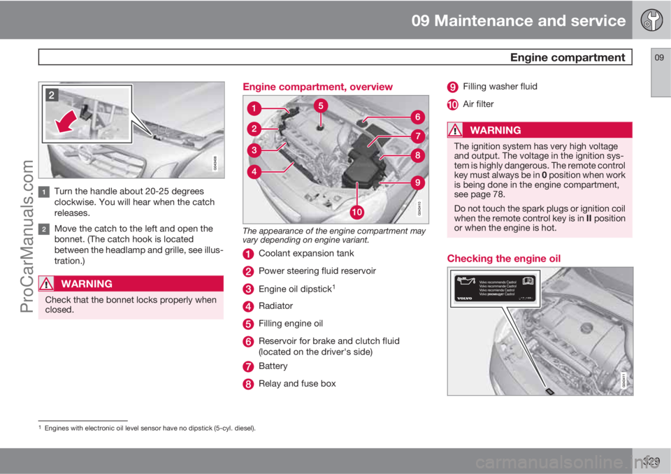
Turn the handle about 20-25 degrees
clockwise. You will hear when the catch
releases.
Move the catch to the left and open the
bonnet. (The catch hook is located
between the headlamp and grille, see illus-
tration.)
WARNING
Check that the bonnet locks properly when
closed.
Engine compartment, overview
The appearance of the engine compartment may
vary depending on engine variant.
Coolant expansion tank
Power steering fluid reservoir
Engine oil dipstick1
Radiator
Filling engine oil
Reservoir for brake and clutch fluid
(located on the driver's side)
Battery
Relay and fuse box
Filling washer fluid
Air filter
WARNING
The ignition system has very high voltage
and output. The voltage in the ignition sys-
tem is highly dangerous. The remote control
key must always be in 0 position when work
is being done in the engine compartment,
see page 78.
Do not touch the spark plugs or ignition coil
when the remote control key is in II position
or when the engine is hot.
Checking the engine oil
1Engines with electronic oil level sensor have no dipstick (5-cyl. diesel).
ProCarManuals.com
Page 346 of 422
09 Maintenance and service
Battery 09
344
Operation
The service life and function of the battery is
influenced by factors such as the number of
starts, discharging, driving style, driving con-
ditions, climatic conditions etc.
•Never disconnect the battery when the
engine is running.
•Check that the cables to the battery are
correctly connected and properly tight-
ened.
WARNING
•The battery can generate oxyhydrogen
gas, which is highly explosive. A spark
can be formed if a jump lead is con-
nected incorrectly, and this can be
enough for the battery to explode.
•The battery contains sulphuric acid,
which can cause serious burns.
•If sulphuric acid comes into contact
with eyes, skin or clothing, flush with
large quantities of water. If acid
splashes into the eyes - seek medical
attention immediately.
NOTE
The life of the battery is shortened if it
becomes discharged repeatedly.
The life of the battery is affected by several
factors, including driving conditions and cli-
mate. Battery starting capacity decreases
gradually with time and therefore needs to
be recharged if the car is not used for a
longer time or when it is only driven short
distances. Extreme cold further limits star-
ting capacity.
To maintain the battery in good condition, at
least 15 minutes of driving/week is recom-
mended or that the battery is connected to
a battery charger with automatic trickle
charging.
A battery that is kept fully charged has a
maximum service life.
IMPORTANT
Never use a quick charger to charge the
battery.
IMPORTANT
If the following instruction is not observed
then the energy saving function for infotain-
ment may be temporarily disengaged, and/
or the message in the information display
about the main battery's state of charge
may be temporarily inapplicable, following
the connection of an external battery or bat-
tery charger:
•The negative battery terminal on the
car's main battery must never be used
for connecting an external battery or
battery charger - only the car chassis
may be used as the grounding point.
See the section "Start assistance" - for a
description of how the cable clamps must
be attached.
ProCarManuals.com
Page 347 of 422

09 Maintenance and service
Battery09
345 Symbols on the battery
Use protective goggles.
Further information in the
owner's manual.
Store the battery out of
the reach of children.
The battery contains cor-
rosive acid.
Avoid sparks and naked
flames.
Risk of explosion.
Must be taken for recy-
cling.
NOTE
An expended battery must be recycled in an
environmentally responsible manner - it
contains lead.
Replacing the main battery
RemovalFirst of all: Take the remote control key from
the ignition switch and wait at least 5 minutes
before any electrical connections are touched
- this is because the car's electrical system
needs to store the necessary information to
control modules.
ProCarManuals.com
Page 354 of 422
09 Maintenance and service
Fuses 09
352* Option/accessory, for more information, see Introduction.
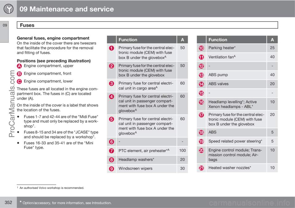
General fuses, engine compartmentOn the inside of the cover there are tweezers
that facilitate the procedure for the removal
and fitting of fuses.
Positions (see preceding illustration)Engine compartment, upper
Engine compartment, front
Engine compartment, lower
These fuses are all located in the engine com-
partment box. The fuses in (C) are located
under (A).
On the inside of the cover is a label that shows
the location of the fuses.
•Fuses 1-7 and 42-44 are of the "Midi Fuse"
type and must only be replaced by a work-
shop
1.
•Fuses 8-15 and 34 are of the "JCASE" type
and should be replaced by a workshop1.
•Fuses 16-33 and 35-41 are of the "Mini
Fuse" type.
FunctionA
Primary fuse for the central elec-
tronic module (CEM) with fuse
box B under the glovebox
A
50
Primary fuse for the central elec-
tronic module (CEM) with fuse
box B under the glovebox50
Primary fuse for central electri-
cal unit in cargo areaA60
Primary fuse for central electri-
cal unit in passenger compart-
ment with fuse box A under the
glovebox
A
60
Primary fuse for central electri-
cal unit in passenger compart-
ment with fuse box A under the
glovebox
A
60
--
PTC element, air preheater*A100
Headlamp washers*20
Windscreen wipers30
FunctionA
Parking heater*25
Ventilation fanA40
--
ABS pump40
ABS valves20
--
Headlamp levelling*; Active
Xenon headlamps - ABL*10
Primary fuse for the central elec-
tronic module (CEM) with fuse
box B under the glovebox20
ABS5
Speed related power steering*5
Engine control module; Trans-
mission control module; Air-
bags10
Heated washer nozzles*10
1An authorised Volvo workshop is recommended.
ProCarManuals.com
Page 358 of 422
09 Maintenance and service
Fuses 09
356* Option/accessory, for more information, see Introduction.
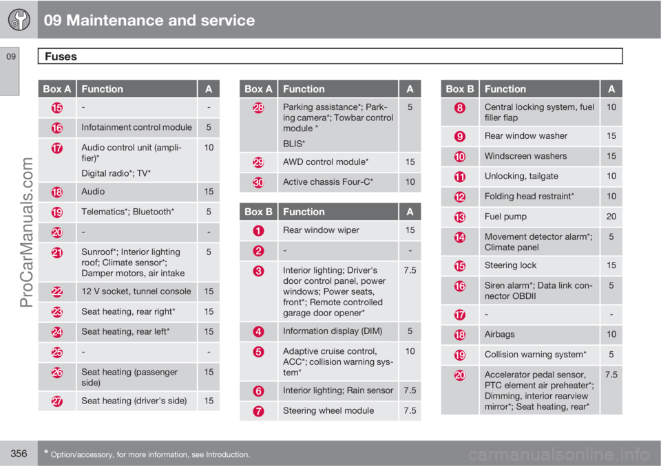
Box AFunctionA
--
Infotainment control module5
Audio control unit (ampli-
fier)*
Digital radio*; TV*10
Audio15
Telematics*; Bluetooth*5
--
Sunroof*; Interior lighting
roof; Climate sensor*;
Damper motors, air intake5
12 V socket, tunnel console15
Seat heating, rear right*15
Seat heating, rear left*15
--
Seat heating (passenger
side)15
Seat heating (driver's side)15
Box AFunctionA
Parking assistance*; Park-
ing camera*; Towbar control
module *
BLIS*5
AWD control module*15
Active chassis Four-C*10
Box BFunctionA
Rear window wiper15
--
Interior lighting; Driver's
door control panel, power
windows; Power seats,
front*; Remote controlled
garage door opener*7.5
Information display (DIM)5
Adaptive cruise control,
ACC*; collision warning sys-
tem*10
Interior lighting; Rain sensor7.5
Steering wheel module7.5
Box BFunctionA
Central locking system, fuel
filler flap10
Rear window washer15
Windscreen washers15
Unlocking, tailgate10
Folding head restraint*10
Fuel pump20
Movement detector alarm*;
Climate panel5
Steering lock15
Siren alarm*; Data link con-
nector OBDII5
--
Airbags10
Collision warning system*5
Accelerator pedal sensor,
PTC element air preheater*;
Dimming, interior rearview
mirror*; Seat heating, rear*7.5
ProCarManuals.com
Page 360 of 422
09 Maintenance and service
Fuses 09
358* Option/accessory, for more information, see Introduction.
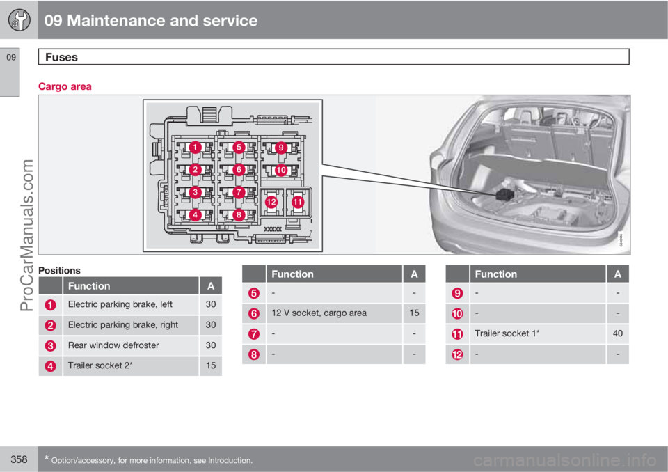
Cargo area
Positions
FunctionA
Electric parking brake, left30
Electric parking brake, right30
Rear window defroster30
Trailer socket 2*15
FunctionA
--
12 V socket, cargo area15
--
--
FunctionA
--
--
Trailer socket 1*40
--
ProCarManuals.com