warning light VOLVO V60 2021 Owner's Manual
[x] Cancel search | Manufacturer: VOLVO, Model Year: 2021, Model line: V60, Model: VOLVO V60 2021Pages: 661, PDF Size: 12.68 MB
Page 216 of 661
||
CLIMATE CONTROL
* Option/accessory.
214
Activating and deactivating the heated rear seats from the rear seat
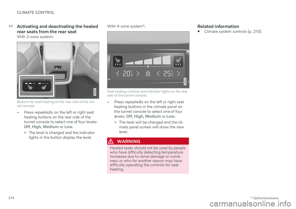
With 2-zone system:
Buttons for seat heating on the rear side of the tun- nel console.
âPress repeatedly on the left or right seat heating buttons on the rear side of thetunnel console to select one of four levels:
Off, High, Medium or Low.
> The level is changed and the indicator lights in the button display the level. With 4-zone system
*:
Seat heating controls and indicator lights on the rear side of the tunnel console.
âPress repeatedly on the left or right seat heating buttons in the climate panel onthe tunnel console to select one of four levels:
Off, High, Medium or Low.
> The level will be changed and the cli- mate panel screen will show the new level.
WARNING
Heated seats should not be used by people who have difficulty detecting temperatureincreases due to nerve damage or numb-ness or who for another reason may havedifficulty operating the controls for seatheating.
Related information
Climate system controls (p. 210)
Page 246 of 661
||
KEY, LOCKS AND ALARM
* Option/accessory.
244 approx. 1.5 meter (5 feet) along the sides of the vehicle or approx. 1 meter (3 feet) from thetailgate.
NOTE
The functions of the remote control key can be disrupted by ambient radio waves,buildings, topographical conditions, etc.The vehicle can always be locked/unlockedusing the key blade.
If the remote key is removed from the vehicle
If the remote key is removed from the vehicle while the engine is run- ning, the warning message
Vehicle
key not found Removed from
vehicle will be displayed in the instrument
panel and an audible signal will sound when the last door is closed.
The message will disappear when the key is returned to the vehicle and the O button on
the right-side steering wheel keypad ispressed or when the last door is closed again.
Related information
Remote key (p. 238)
Antenna locations for the start and locksystem (p. 257)
Keyless and touch-sensitive surfaces
*
(p. 254)
Replacing the remote key's battery
The battery in the remote key must be replaced when it is discharged.
NOTE
All batteries have a limited service life and must eventually be replaced (does notapply for Key Tag). The battery's service lifevaries depending on how often thevehicle/key is used.
The remote key battery should be replaced if
the information symbol illuminates and the message
Vehicle key bat. low is dis-
played in the instrument panel
the locks do not react after several attempts to lock or unlock the vehicleusing the remote key within approx.20 meter (65 feet) from the vehicle.
NOTE
Move closer to the vehicle and try to unlock it again.
The battery in the smaller key without but- tons 7
(the Key Tag) cannot be replaced. A new key can be ordered from an authorized Volvo workshop.
CAUTION
An end-of-life Key Tag must be turned in to an authorized Volvo workshop. The keymust be deleted from the vehicle becauseit can still be used to start the vehicle viabackup start.
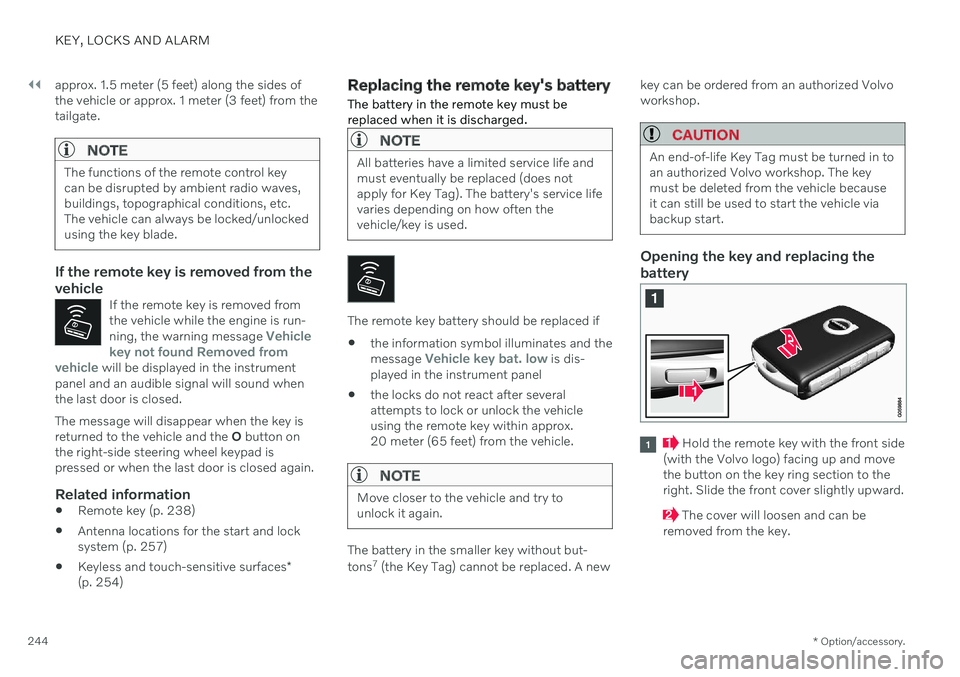
Opening the key and replacing the battery
Hold the remote key with the front side
(with the Volvo logo) facing up and move the button on the key ring section to theright. Slide the front cover slightly upward.
The cover will loosen and can be
removed from the key.
Page 259 of 661
KEY, LOCKS AND ALARM
* Option/accessory.257
2. Lift the outer handle to open the tailgate.
CAUTION
Only light pressure on the rubberized pressure plate is necessary to releasethe tailgate's locking mechanism.
Use the handle to lift the tailgate and donot apply force to the rubberized pres-sure plate. Too much force can damagethe pressure plate's electrical connec-tions.
Hands-free unlocking of the tailgate is also possible using a foot movement under the rearbumper; see the separate section.
WARNING
Do not drive with the tailgate open. Toxic exhaust fumes can be sucked into the vehi-cle through the cargo compartment.
Related information
Keyless locking and unlocking
* (p. 255)
Keyless and touch-sensitive surfaces
*
(p. 254)
Remote key range (p. 243)
Operating the tailgate with a foot move- ment
* (p. 263)
Antenna locations for the start and lock system
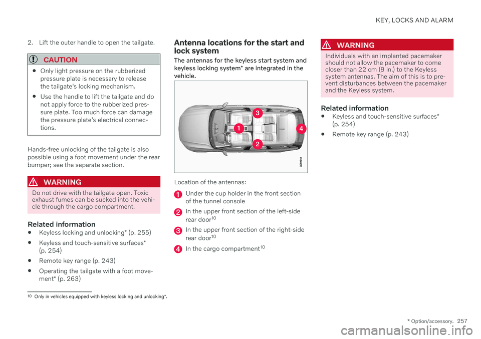
The antennas for the keyless start system and keyless locking system * are integrated in the
vehicle.
Location of the antennas:
Under the cup holder in the front section of the tunnel console
In the upper front section of the left-side rear door 10
In the upper front section of the right-side rear door10
In the cargo compartment 10
WARNING
Individuals with an implanted pacemaker should not allow the pacemaker to comecloser than 22 cm (9 in.) to the Keylesssystem antennas. The aim of this is to pre-vent disturbances between the pacemakerand the Keyless system.
Related information
Keyless and touch-sensitive surfaces
*
(p. 254)
Remote key range (p. 243)
10
Only in vehicles equipped with keyless locking and unlocking *.
Page 268 of 661
||
KEY, LOCKS AND ALARM
266
Related information
Private Locking (p. 264)
Alarm The alarm emits sound and light signals if anyone without a valid remote key attemptsto break into the vehicle or interferes with thestart battery or alarm siren.
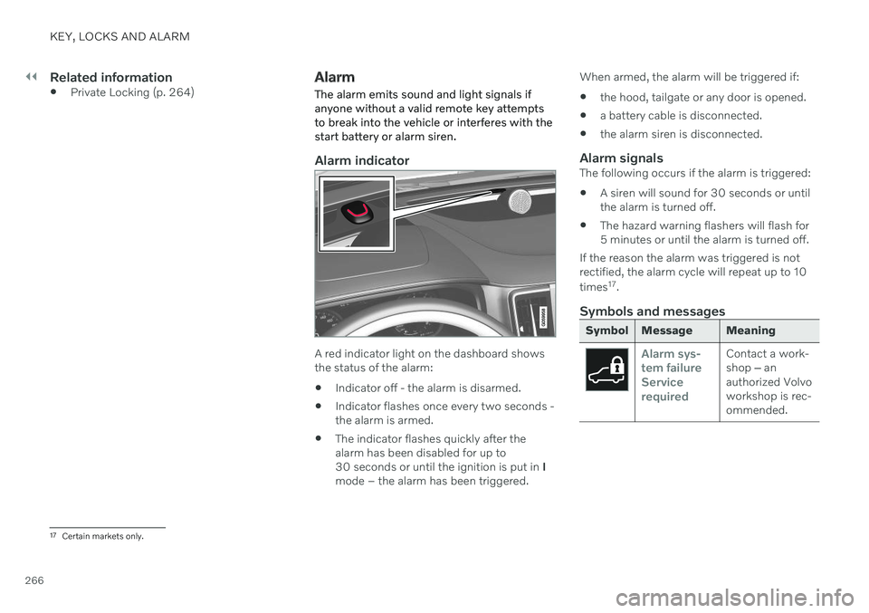
Alarm indicator
A red indicator light on the dashboard shows the status of the alarm:
Indicator off - the alarm is disarmed.
Indicator flashes once every two seconds -the alarm is armed.
The indicator flashes quickly after thealarm has been disabled for up to30 seconds or until the ignition is put in
I
mode â the alarm has been triggered. When armed, the alarm will be triggered if:
the hood, tailgate or any door is opened.
a battery cable is disconnected.
the alarm siren is disconnected.
Alarm signalsThe following occurs if the alarm is triggered:
A siren will sound for 30 seconds or untilthe alarm is turned off.
The hazard warning flashers will flash for5 minutes or until the alarm is turned off.
If the reason the alarm was triggered is notrectified, the alarm cycle will repeat up to 10 times 17
.
Symbols and messages
Symbol Message Meaning
Alarm sys- tem failureServicerequiredContact a work- shop â an
authorized Volvoworkshop is rec-ommended.
17 Certain markets only.
Page 279 of 661
DRIVER SUPPORT
}}
* Option/accessory.277
Activating or deactivating Connected Safety
For Connected Safety to be able to share information about road conditions with otherdrivers, the function must be activated. If youdo not wish to share information, the functioncan be deactivated.
Activate or deactivate the function using this button inthe center display's Functionview.
Illuminated button indicator light â the function is activated.
Extinguished button indicator light â thefunction is deactivated.
At activation, the driver must accept the spe-cial terms and conditions shown in the display before an Internet connection 12
can be estab-
lished. The driver must, for example, accept that data is sent from the vehicle using thedriver's cellular phone. Even when your vehicle is not connected to the Internet, you will still be notified if the sys-tem in your own vehicle detects slippery roadconditions. For Connected Safety to functionat full capacity, your vehicle needs to be con-nected to the Internet.
Related information
Connected Safety (p. 276)
Internet-connected vehicle
* (p. 500)
Terms of use and data sharing (p. 506)
Connected Safety limitations (p. 277)
Connected Safety limitations
Information on vehicles with activated hazard warning flashers or which have detected slip-pery road conditions is not always communi-cated between all vehicles in the affectedarea.
This may be the case if: No or insufficient Internet connection.
The maneuvers (steering wheel move- ments, acceleration or braking) made bythe vehicles on slippery surfaces are tooweak for friction between the tires androad to be detected.
Vehicles that have detected slippery roadconditions or activated hazard warningflashers have not activated the function.
Vehicles that have detected slippery roadconditions or activated hazard warningflashers are not equipped with the func-tion.
Insufficient GPS/satellite navigation mayprevent warnings.
Slippery road conditions were detected orhazard warning flashers were activated ona road that is not registered in the VolvoCars database.
Connected Safety is not developed on allmarkets and does not cover all areas. Con-
12
There may be a charge for transmitting data over the Internet, depending on your service plan.
Page 281 of 661
DRIVER SUPPORT
}}
* Option/accessory.279
Related information
Driver support systems (p. 270)
Activating or deactivating Road Sign Infor- mation
* (p. 279)
Road Sign Information
* display (p. 279)
Road Sign Information and SensusNavigation
* (p. 280)
Speed limit and speed camera warningsfrom Road Sign Information
* (p. 280)
Road Sign Information
* limitations
(p. 282)
Activating or deactivating Road Sign Information *
The Road Sign Information (RSI 16
) function is
optional â the driver can choose to have the function activated or deactivated.
Activate or deactivate the function using this button inthe center display's Functionview.
Illuminated button indicator light â the function is activated.
Extinguished button indicator light â thefunction is deactivated.
Related information
Road Sign Information
* (p. 278)
Road Sign Information
* limitations
(p. 282)
Road Sign Information * display
Road Sign Information (RSI 17
) displays road
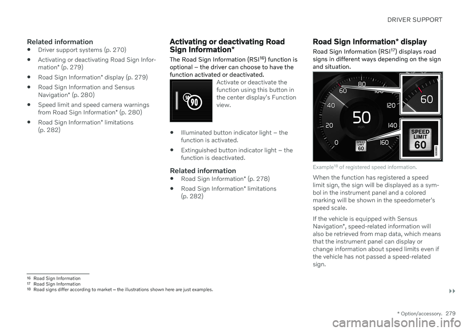
signs in different ways depending on the sign and situation.
Example 18
of registered speed information.
When the function has registered a speed limit sign, the sign will be displayed as a sym-bol in the instrument panel and a coloredmarking will be shown in the speedometer'sspeed scale. If the vehicle is equipped with Sensus Navigation *, speed-related information will
also be retrieved from map data, which means that the instrument panel can display orchange information about speed limits even ifthe vehicle has not passed a speed-relatedsign.
16 Road Sign Information
17 Road Sign Information
18 Road signs differ according to market â the illustrations shown here are just examples.
Page 286 of 661
||
DRIVER SUPPORT
* Option/accessory.
284
WARNING
The function is supplementary driver support intended to facilitate drivingand help make it safer â it cannot han-dle all situations in all traffic, weatherand road conditions.
The driver is advised to read all sec-tions in the Owner's Manual about thisfunction to learn of its limitations,which the driver must be aware ofbefore using the function.
Driver support functions are not a sub-stitute for the driver's attention andjudgment. The driver is always respon-sible for ensuring the vehicle is drivenin a safe manner, at the appropriatespeed, with an appropriate distance toother vehicles, and in accordance withcurrent traffic rules and regulations.
Using engine braking instead of applying the brakes
Cruise Control regulates speed by lightly applying the brakes. On downgrades, it cansometimes be desirable to roll a bit faster andlet speed be reduced instead by engine brak-ing alone. The driver can temporarily disen-gage the Cruise Control braking function. To disengage CC:
âPress the accelerator pedal about halfway down and then release it.
> Cruise Control will automatically disen-
gage the automatic brake function and speed will only be reduced using theengine braking function.
Related information
Driver support systems (p. 270)
Selecting and activating cruise control(p. 284)
Deactivating cruise control (p. 285)
Cruise control standby mode (p. 286)
Adjusting set speed for driver support(p. 313)
Switching between cruise control and Adaptive Cruise Control
* in the center dis-
play (p. 293)
Selecting and activating cruise control The Cruise Control (CC 29
) function must be
selected and activated in order to regulate speed.
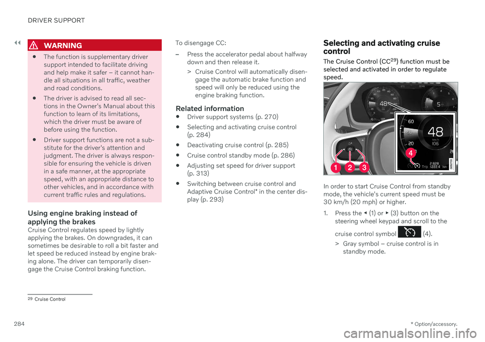
In order to start Cruise Control from standby mode, the vehicle's current speed must be30 km/h (20 mph) or higher.
1. Press the â (1) or ⶠ(3) button on the
steering wheel keypad and scroll to the cruise control symbol
(4).
> Gray symbol â cruise control is in standby mode.
29Cruise Control
Page 292 of 661
||
DRIVER SUPPORT
* Option/accessory.
290 your vehicle's current speed must be at least 15 km/h (9 mph).
1. Press the â (2) or ⶠ(3) button on the
steering wheel keypad and scroll to the Adaptive Cruise Control symbol
(4).
> Gray symbol â Adaptive Cruise Control is in standby mode.
2. When Speed Limiter is selected, press
(1) on the steering wheel keypad to
activate.
> White symbol â Speed Limiter starts and the current speed is stored as the maximum speed.
Reactivating Adaptive Cruise Control to the last stored speed
âWhen Adaptive Cruise Control is selected, press
on the steering wheel keypad to
activate.
> The Cruise Control marking in the instrument panel will change from GRAY to WHITE and the vehicle willthen return to the most recently setspeed.
WARNING
A noticeable increase in speed may follow when the speed is resumed with the
steering wheel button.
Related information
Adaptive Cruise Control
* (p. 286)
Deactivating Adaptive Cruise Control
*
(p. 290)
Switching between cruise control and Adaptive Cruise Control
* in the center dis-
play (p. 293)
Adaptive Cruise Control
* limitations
(p. 292)
Deactivating Adaptive Cruise Control *41
Adaptive Cruise Control (ACC 42
) can be deac-
tivated and switched off.
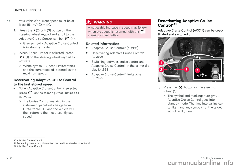
1. Press the button on the steering
wheel (1).
> The symbol and markings turn gray â Adaptive Cruise Control goes into standby mode. The time interval indica-tor light and any symbols for the targetvehicle will go out.
40Adaptive Cruise Control
41 Depending on market, this function can be either standard or optional.
42 Adaptive Cruise Control
Page 299 of 661
DRIVER SUPPORT
}}
297
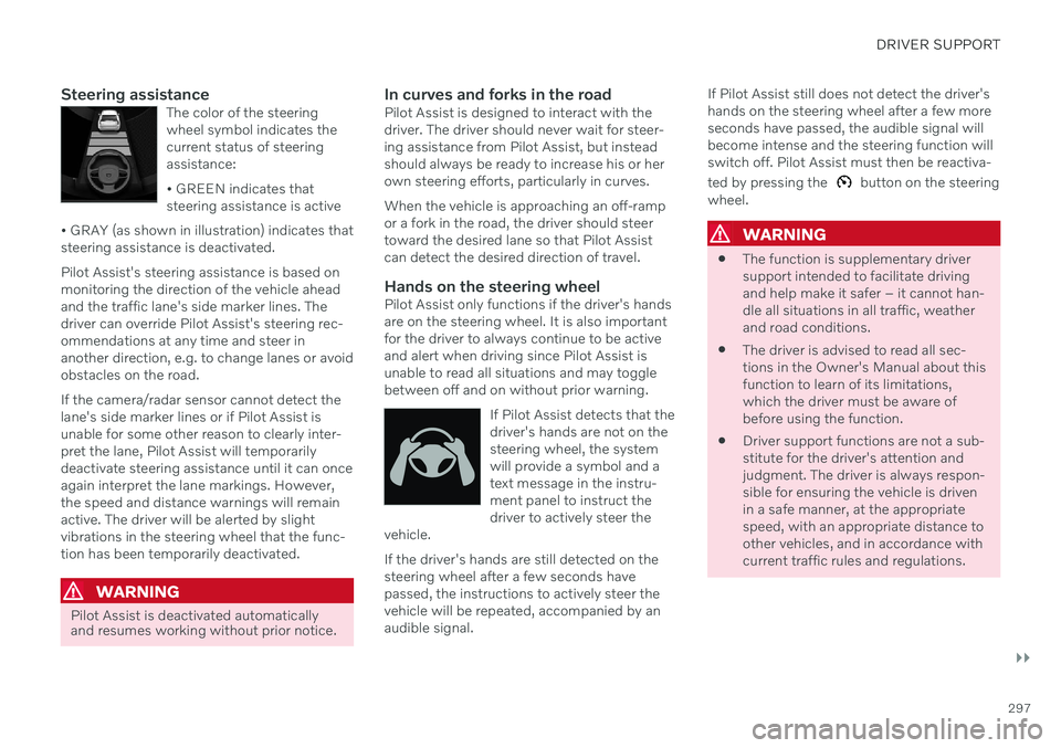
Steering assistanceThe color of the steering wheel symbol indicates thecurrent status of steeringassistance: ⢠GREEN indicates that steering assistance is active
⢠GRAY (as shown in illustration) indicates thatsteering assistance is deactivated.
Pilot Assist's steering assistance is based on monitoring the direction of the vehicle aheadand the traffic lane's side marker lines. Thedriver can override Pilot Assist's steering rec-ommendations at any time and steer inanother direction, e.g. to change lanes or avoidobstacles on the road. If the camera/radar sensor cannot detect the lane's side marker lines or if Pilot Assist isunable for some other reason to clearly inter-pret the lane, Pilot Assist will temporarilydeactivate steering assistance until it can onceagain interpret the lane markings. However,the speed and distance warnings will remainactive. The driver will be alerted by slightvibrations in the steering wheel that the func-tion has been temporarily deactivated.
WARNING
Pilot Assist is deactivated automatically and resumes working without prior notice.
In curves and forks in the roadPilot Assist is designed to interact with the driver. The driver should never wait for steer-ing assistance from Pilot Assist, but insteadshould always be ready to increase his or herown steering efforts, particularly in curves. When the vehicle is approaching an off-ramp or a fork in the road, the driver should steertoward the desired lane so that Pilot Assistcan detect the desired direction of travel.
Hands on the steering wheelPilot Assist only functions if the driver's handsare on the steering wheel. It is also importantfor the driver to always continue to be activeand alert when driving since Pilot Assist isunable to read all situations and may togglebetween off and on without prior warning.
If Pilot Assist detects that thedriver's hands are not on thesteering wheel, the systemwill provide a symbol and atext message in the instru-ment panel to instruct thedriver to actively steer the
vehicle.
If the driver's hands are still detected on the steering wheel after a few seconds havepassed, the instructions to actively steer thevehicle will be repeated, accompanied by anaudible signal. If Pilot Assist still does not detect the driver'shands on the steering wheel after a few moreseconds have passed, the audible signal willbecome intense and the steering function willswitch off. Pilot Assist must then be reactiva- ted by pressing the
button on the steering
wheel.
WARNING
The function is supplementary driver support intended to facilitate drivingand help make it safer â it cannot han-dle all situations in all traffic, weatherand road conditions.
The driver is advised to read all sec-tions in the Owner's Manual about thisfunction to learn of its limitations,which the driver must be aware ofbefore using the function.
Driver support functions are not a sub-stitute for the driver's attention andjudgment. The driver is always respon-sible for ensuring the vehicle is drivenin a safe manner, at the appropriatespeed, with an appropriate distance toother vehicles, and in accordance withcurrent traffic rules and regulations.
Page 303 of 661
DRIVER SUPPORT
}}
* Option/accessory.301
The driver must keep their hands on the steering wheel.
There must be a vehicle ahead (targetvehicle) within a reasonable distance oryour vehicle's current speed must be atleast 15 km/h (9 mph).
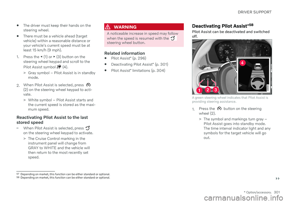
1. Press the â (1) or ⶠ(3) button on the
steering wheel keypad and scroll to the Pilot Assist symbol
(4).
> Gray symbol â Pilot Assist is in standby mode.
2. When Pilot Assist is selected, press
(2) on the steering wheel keypad to acti- vate.
> White symbol â Pilot Assist starts and
the current speed is stored as the maxi- mum speed.
Reactivating Pilot Assist to the last stored speed
âWhen Pilot Assist is selected, press on the steering wheel keypad to activate.
> The Cruise Control marking in theinstrument panel will change from GRAY to WHITE and the vehicle willthen return to the most recently setspeed.
WARNING
A noticeable increase in speed may follow when the speed is resumed with the
steering wheel button.
Related information
Pilot Assist
* (p. 296)
Deactivating Pilot Assist
* (p. 301)
Pilot Assist
* limitations (p. 304)
Deactivating Pilot Assist *58
Pilot Assist can be deactivated and switched off.
A green steering wheel indicates that Pilot Assist is providing steering assistance.
1. Press the button on the steering
wheel (2).
> The symbol and markings turn gray â Pilot Assist goes into standby mode. The time interval indicator light and anysymbols for the target vehicle will goout.
57Depending on market, this function can be either standard or optional.
58 Depending on market, this function can be either standard or optional.