VOLVO V90 2018 Owner´s Manual
Manufacturer: VOLVO, Model Year: 2018, Model line: V90, Model: VOLVO V90 2018Pages: 656, PDF Size: 11.78 MB
Page 531 of 656
WHEELS AND TIRES
}}
* Option/accessory.529
Calibrating the tire pressure
monitoring system *
In order for the tire pressure monitoring system, Tyre Pressure Monitoring System (TPMS), tofunction correctly, tire pressure reference valuesmust be set correctly. This must be done eachtime the tires are changed or the tire pressure isadjusted.
For example, when driving with a heavy load or at high speeds (over 160 km/h (100 mph)), tirepressure should be adjusted to the Volvo-recom-mended tire pressure values. The system shouldthen be recalibrated.
1. Switch off the ignition.
2. Inflate the tires to the pressure indicated on the tire pressure placard on the driver's side B pillar.
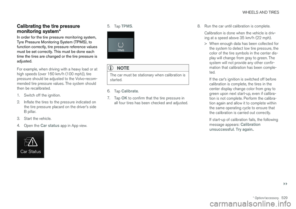
3. Start the vehicle. 4. Open the
Car status app in App view.
5.Tap TPMS.
NOTE
The car must be stationary when calibration is started.
6.Tap Calibrate.
7. Tap
OK to confirm that the tire pressure in
all four tires has been checked and adjusted. 8. Run the car until calibration is complete.
Calibration is done when the vehicle is driv- ing at a speed above 35 km/h (22 mph).
> When enough data has been collected forthe system to detect low tire pressure, the color of the tire symbols in the center dis-play will change from gray to green. Thesystem will not provide any other confir-mation that calibration has been comple-ted. If the car's ignition is switched off before calibration is complete, the tires in thecenter display change color from gray togreen upon next start-up, even if calibra-tion is not complete. Perform the calibra-tion again and allow it to complete withinthe same operating cycle to ensure thatthe calibration is carried out correctly. If start-up of calibration fails, the following message appears:
Calibration
unsuccessful. Try again..
Page 532 of 656
||
WHEELS AND TIRES
* Option/accessory.
530
NOTE
Always remember to calibrate the Tire Pres- sure Monitoring System when the wheelshave been changed or the tire inflation pres-sure has been corrected according to the tirepressure decal or tire inflation pressure table. If correct reference values have not been set, the system cannot issue low tire pressurealerts correctly. The vehicle must be stationary with the engine running to access the calibration but-ton and to start the calibration process.
WARNING
The exhaust gases contain carbon monoxide, which is invisible and odorless but very poi-sonous. For this reason, always perform thecalibration procedure outdoors or in a work-shop with exhaust gas evacuation equipment.
Related information
• Recommended tire pressure (p. 527)
• Adjusting tire pressure (p. 526)
• Viewing tire pressure status in the center display
* (p. 530)
• Action when warned of low tire pressure (p. 531)
• Tire pressure monitoring system
* (p. 527)
Viewing tire pressure status in the
center display *
With the system for tire pressure monitoring, Tyre Pressure Monitoring System (TPMS), tirepressure status can be viewed in the center dis-play.
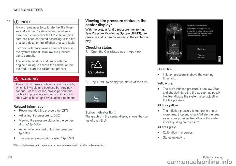
Checking status1. Open the Car status app in App view.
2.Tap TPMS to display the status of the tires.
Status indicator light
The graphic in the center display shows the sta- tus of each tire 8
.
Green tire:
• Inflation pressure is above the warning threshold.
Yellow tire:
• The tire's inflation pressure is too low. Stopand check/inflate the tire as soon as possi-ble. Recalibrate the system after adjustingthe tire pressure.
All tires yellow:
• The inflation pressure is too low in one ormore tires. Stop and check/inflate the tiresas soon as possible. Recalibrate the systemafter adjusting tire pressure.
All tires gray: • Calibration in progress.
• Status unknown.
8
The illustration is generic. Layout may vary depending on vehicle model or software version.
Page 533 of 656
WHEELS AND TIRES
}}
* Option/accessory.531
The vehicle may need to be driven for a few minutes at a speed above 35 km/h (22 mph) toactivate the system. All tires gray and a message: •
Tire pressure system Temporarily
unavailable. The indicator symbol will flash
for about 1 minute and then glow steadily. The system is temporarily unavailable and willbe activated momentarily.
•
Tire pressure system Service required.
The indicator symbol will flash for about 1 minute and then glow steadily. If the system is not working properly, contact a workshop 9
.
Related information
• Calibrating the tire pressure monitoring sys- tem
* (p. 529)
• Action when warned of low tire pressure (p. 531)
• Tire pressure monitoring system
* (p. 527)
• Vehicle status (p. 570)
Action when warned of low tirepressure
When the tire pressure monitoring system, Tyre Pressure Monitoring System (TPMS), detectslow pressure in one or more of the vehicle'stires, the driver will be alerted that action is nee-ded.
If the system's indicator symbol illumi- nates and the message Tire pressure
low is displayed, check the tire pres-
sure and inflate if necessary.
1. Switch off the ignition.
2. Check the inflation pressure on all four tires using a tire pressure gauge.
3. Inflate the tire to the correct pressure (see the tire pressure decal on the driver's side door pillar).
4. Through calibration of the system via the center display after the tire pressure hasbeen adjusted. Please be aware that the indicator symbol will not go out until the low tire pressure hasbeen corrected and the system has beenrecalibrated.
NOTE
To help prevent incorrect inflation pressure, pressure should be checked when the tiresare cold. The tires are considered to be coldwhen they have reached the same tempera-ture as the ambient temperature (about 3hours after the vehicle was last driven). Afterdriving for a few kilometers, the tires will warmup and the pressure will increase.
NOTE
• After inflating a tire, always replace the valve cap to help prevent valve damagecaused by gravel, dirt, etc.
• Use plastic valve caps only. Metal capscould corrode and become difficult toremove.
WARNING
•Incorrect inflation pressure could lead to tire failure, which could cause the driverto lose control of the vehicle.
• The system cannot predict sudden tiredamage.
9
An authorized Volvo workshop is recommended.
Page 534 of 656
||
WHEELS AND TIRES
* Option/accessory.
532
Related information
• Recommended tire pressure (p. 527)
• Adjusting tire pressure (p. 526)
• Calibrating the tire pressure monitoring sys- tem
* (p. 529)
• Viewing tire pressure status in the centerdisplay
* (p. 530)
• Tire pressure monitoring system
* (p. 527)
• Inflate tires with the compressor included in the tire sealing system (p. 545)
When changing wheels
The wheels can be changed, e.g. to switch to snow tires or spare tires. Follow the applicableinstructions for removing and installing thewheel.
Changing to tires of another dimensionMake sure that the tire dimension is approved for use on the vehicle. If you change to tires of another dimension, con- tact an authorized Volvo workshop to update thevehicle's software. A software update may benecessary when changing to tires of larger/smaller dimensions or when changing to or fromsnow tires.
Related information
• Removing a wheel (p. 534)
• Installing a wheel (p. 536)
• Tool kit (p. 532)
• Snow tires (p. 539)
• Spare wheel (p. 537)
• Wheel bolts (p. 533)
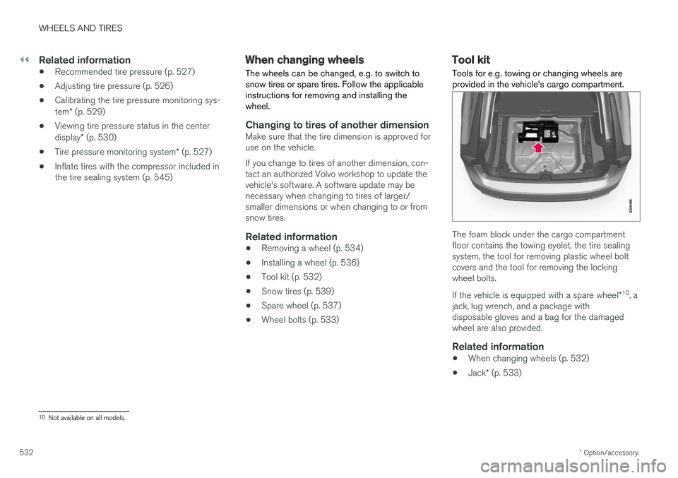
Tool kit Tools for e.g. towing or changing wheels are provided in the vehicle's cargo compartment.
The foam block under the cargo compartment floor contains the towing eyelet, the tire sealingsystem, the tool for removing plastic wheel boltcovers and the tool for removing the lockingwheel bolts. If the vehicle is equipped with a spare wheel
*10
, a
jack, lug wrench, and a package with disposable gloves and a bag for the damagedwheel are also provided.
Related information
• When changing wheels (p. 532)
• Jack
* (p. 533)
10
Not available on all models.
Page 535 of 656
WHEELS AND TIRES
}}
* Option/accessory.533
Jack*
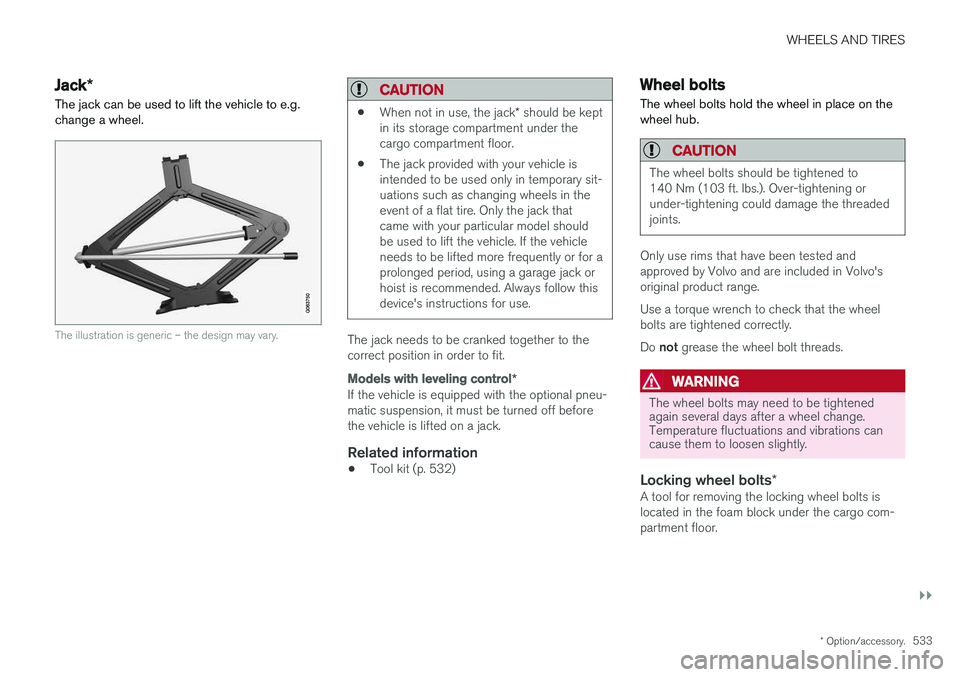
The jack can be used to lift the vehicle to e.g. change a wheel.
The illustration is generic – the design may vary.
CAUTION
• When not in use, the jack
* should be kept
in its storage compartment under the cargo compartment floor.
• The jack provided with your vehicle isintended to be used only in temporary sit-uations such as changing wheels in theevent of a flat tire. Only the jack thatcame with your particular model shouldbe used to lift the vehicle. If the vehicleneeds to be lifted more frequently or for aprolonged period, using a garage jack orhoist is recommended. Always follow thisdevice's instructions for use.
The jack needs to be cranked together to the correct position in order to fit.
Models with leveling control
*
If the vehicle is equipped with the optional pneu- matic suspension, it must be turned off beforethe vehicle is lifted on a jack.
Related information
•Tool kit (p. 532)
Wheel bolts
The wheel bolts hold the wheel in place on the wheel hub.
CAUTION
The wheel bolts should be tightened to 140 Nm (103 ft. lbs.). Over-tightening orunder-tightening could damage the threadedjoints.
Only use rims that have been tested and approved by Volvo and are included in Volvo'soriginal product range. Use a torque wrench to check that the wheel bolts are tightened correctly. Do not grease the wheel bolt threads.
WARNING
The wheel bolts may need to be tightened again several days after a wheel change.Temperature fluctuations and vibrations cancause them to loosen slightly.
Locking wheel bolts *A tool for removing the locking wheel bolts is located in the foam block under the cargo com-partment floor.
Page 536 of 656
||
WHEELS AND TIRES
* Option/accessory.
534
Related information
• Removing a wheel (p. 534)
• Installing a wheel (p. 536)
Removing a wheel
Instructions for removing a wheel when chang- ing wheels. Wheel changes must always be car-ried out correctly.
CAUTION
• When not in use, the jack
* should be kept
in its storage compartment under the cargo compartment floor.
• The jack provided with your vehicle isintended to be used only in temporary sit-uations such as changing wheels in theevent of a flat tire. Only the jack thatcame with your particular model shouldbe used to lift the vehicle. If the vehicleneeds to be lifted more frequently or for aprolonged period, using a garage jack orhoist is recommended. Always follow thisdevice's instructions for use.
WARNING
•Apply the parking brake and put the gear selector in the Park (
P) position.
• Block the wheels standing on the ground, use rigid wooden blocks or large stones.
• Check that the jack is not damaged, thethreads are properly lubricated and it isfree from dirt.
• Be sure the jack is on a firm, level, non-slippery surface and that it is upright andnot leaning.
• The jack must correctly engage in thejack attachment.
• No objects should be placed between thebase of the jack and the ground, orbetween the jack and the attachment baron the vehicle.
• Never let anyone remain in the vehiclewhen it is raised on a jack.
• If a tire must be changed near passingtraffic, make sure all passengers move toa safe location.
• Use a jack intended for the vehicle whenchanging a tire. For any other job, usestands to support the vehicle.
• Never crawl under or allow any part ofyour body to be extended under a vehiclesupported by a jack.
Page 537 of 656
WHEELS AND TIRES
}}
* Option/accessory.535
1. Turn on the vehicle's hazard warning flashers
if a wheel change must be performed in an area with traffic.
2. Apply the parking brake and put the gear selector in P.
For vehicles with
Leveling Control* : If the
vehicle is equipped with pneumatic suspen- sion, this must be switched off before the vehicle is lifted with the jack *.
3. Take out the jack *, lug wrench * and tool for
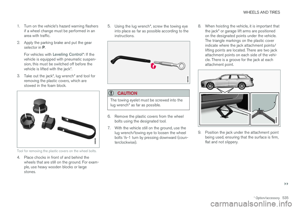
removing the plastic covers, which are stowed in the foam block.
Tool for removing the plastic covers on the wheel bolts.
4. Place chocks in front of and behind the wheels that are still on the ground. For exam- ple, use heavy wooden blocks or largestones. 5.
Using the lug wrench *, screw the towing eye
into place as far as possible according to theinstructions.
CAUTION
The towing eyelet must be screwed into the lug wrench * as far as possible.
6. Remove the plastic covers from the wheel
bolts using the designated tool.
7. With the vehicle still on the ground, use the lug wrench/towing eye to loosen the wheel bolts ½-1 turn by pressing downward (coun-terclockwise). 8. When hoisting the vehicle, it is important that
the jack * or garage lift arms are positioned
on the designated points under the vehicle.The triangle markings on the plastic coverindicate where the jack attachment points/lifting points are located. There are two jackattachment points on each side of the vehi-cle. There is a groove for the jack at eachattachment point.
9. Position the jack under the attachment point being used, ensuring that the surface is firm, flat and not slippery.
Page 538 of 656
||
WHEELS AND TIRES
* Option/accessory.
536 10. Crank it up until it is properly aligned and it is
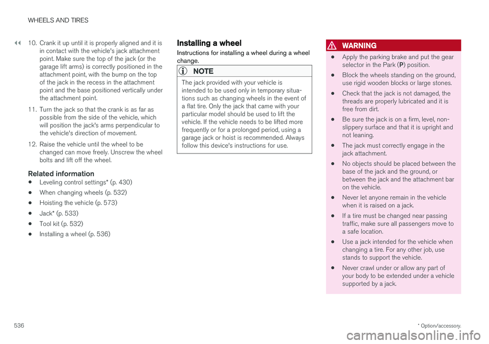
in contact with the vehicle's jack attachment point. Make sure the top of the jack (or thegarage lift arms) is correctly positioned in theattachment point, with the bump on the topof the jack in the recess in the attachmentpoint and the base positioned vertically underthe attachment point.
11. Turn the jack so that the crank is as far as possible from the side of the vehicle, whichwill position the jack's arms perpendicular tothe vehicle's direction of movement.
12. Raise the vehicle until the wheel to be changed can move freely. Unscrew the wheelbolts and lift off the wheel.
Related information
• Leveling control settings
* (p. 430)
• When changing wheels (p. 532)
• Hoisting the vehicle (p. 573)
• Jack
* (p. 533)
• Tool kit (p. 532)
• Installing a wheel (p. 536)
Installing a wheel
Instructions for installing a wheel during a wheel change.
NOTE
The jack provided with your vehicle is intended to be used only in temporary situa-tions such as changing wheels in the event ofa flat tire. Only the jack that came with yourparticular model should be used to lift thevehicle. If the vehicle needs to be lifted morefrequently or for a prolonged period, using agarage jack or hoist is recommended. Alwaysfollow this device's instructions for use.
WARNING
• Apply the parking brake and put the gear selector in the Park (
P) position.
• Block the wheels standing on the ground, use rigid wooden blocks or large stones.
• Check that the jack is not damaged, thethreads are properly lubricated and it isfree from dirt.
• Be sure the jack is on a firm, level, non-slippery surface and that it is upright andnot leaning.
• The jack must correctly engage in thejack attachment.
• No objects should be placed between thebase of the jack and the ground, orbetween the jack and the attachment baron the vehicle.
• Never let anyone remain in the vehiclewhen it is raised on a jack.
• If a tire must be changed near passingtraffic, make sure all passengers move toa safe location.
• Use a jack intended for the vehicle whenchanging a tire. For any other job, usestands to support the vehicle.
• Never crawl under or allow any part ofyour body to be extended under a vehiclesupported by a jack.
Page 539 of 656
WHEELS AND TIRES
}}
* Option/accessory.537
1. Clean the contact surfaces between the
wheel and the wheel hub.
2. Lift the wheel into place. Tighten the wheel bolts securely. Do not grease the wheel bolt threads.
3. Lower the vehicle so that the wheel cannot rotate.
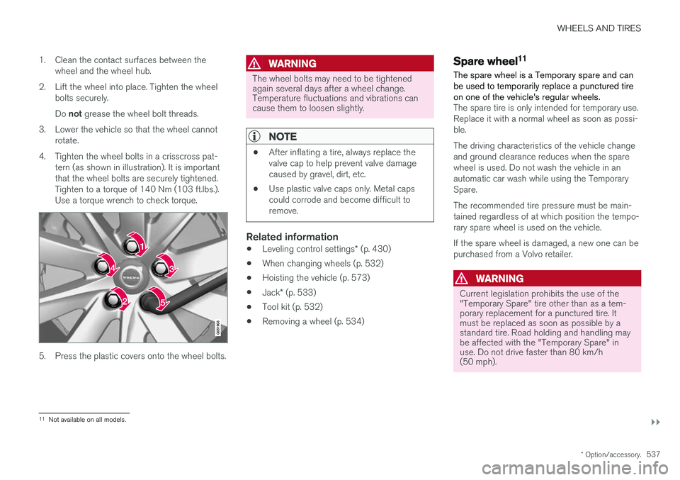
4. Tighten the wheel bolts in a crisscross pat- tern (as shown in illustration). It is important that the wheel bolts are securely tightened.Tighten to a torque of 140 Nm (103 ft.lbs.).Use a torque wrench to check torque.
5. Press the plastic covers onto the wheel bolts.
WARNING
The wheel bolts may need to be tightened again several days after a wheel change.Temperature fluctuations and vibrations cancause them to loosen slightly.
NOTE
• After inflating a tire, always replace the valve cap to help prevent valve damagecaused by gravel, dirt, etc.
• Use plastic valve caps only. Metal capscould corrode and become difficult toremove.
Related information
•
Leveling control settings
* (p. 430)
• When changing wheels (p. 532)
• Hoisting the vehicle (p. 573)
• Jack
* (p. 533)
• Tool kit (p. 532)
• Removing a wheel (p. 534)
Spare wheel11
The spare wheel is a Temporary spare and can be used to temporarily replace a punctured tireon one of the vehicle's regular wheels.
The spare tire is only intended for temporary use. Replace it with a normal wheel as soon as possi-ble. The driving characteristics of the vehicle change and ground clearance reduces when the sparewheel is used. Do not wash the vehicle in anautomatic car wash while using the TemporarySpare. The recommended tire pressure must be main- tained regardless of at which position the tempo-rary spare wheel is used on the vehicle. If the spare wheel is damaged, a new one can be purchased from a Volvo retailer.
WARNING
Current legislation prohibits the use of the "Temporary Spare" tire other than as a tem-porary replacement for a punctured tire. Itmust be replaced as soon as possible by astandard tire. Road holding and handling maybe affected with the "Temporary Spare" inuse. Do not drive faster than 80 km/h(50 mph).
11 Not available on all models.
Page 540 of 656
||
WHEELS AND TIRES
538
WARNING
•The vehicle must never be driven with more than one "Temporary spare" tiremounted.
• Driving with a spare wheel may alter thedriving characteristics of the vehicle.Replace the spare wheel with a normalwheel as soon as possible.
• The spare wheel is smaller than the nor-mal wheel, which affects the vehicle'sground clearance. Watch for high curbsand do not wash the vehicle in an auto-matic car wash when a spare wheel ismounted.
• Follow the manufacturer's recommendedtire inflation pressure for the spare wheel.
• On all-wheel drive vehicles, the drive onthe rear axle can be disconnected.
• If the spare wheel is mounted on thefront axle, snow chains must not be used.
• The spare wheel must not be repaired.
CAUTION
The vehicle must not be driven with wheels of different dimensions or with a spare tire otherthan the one that came with the vehicle. Theuse of different size wheels can seriouslydamage your vehicle's transmission.
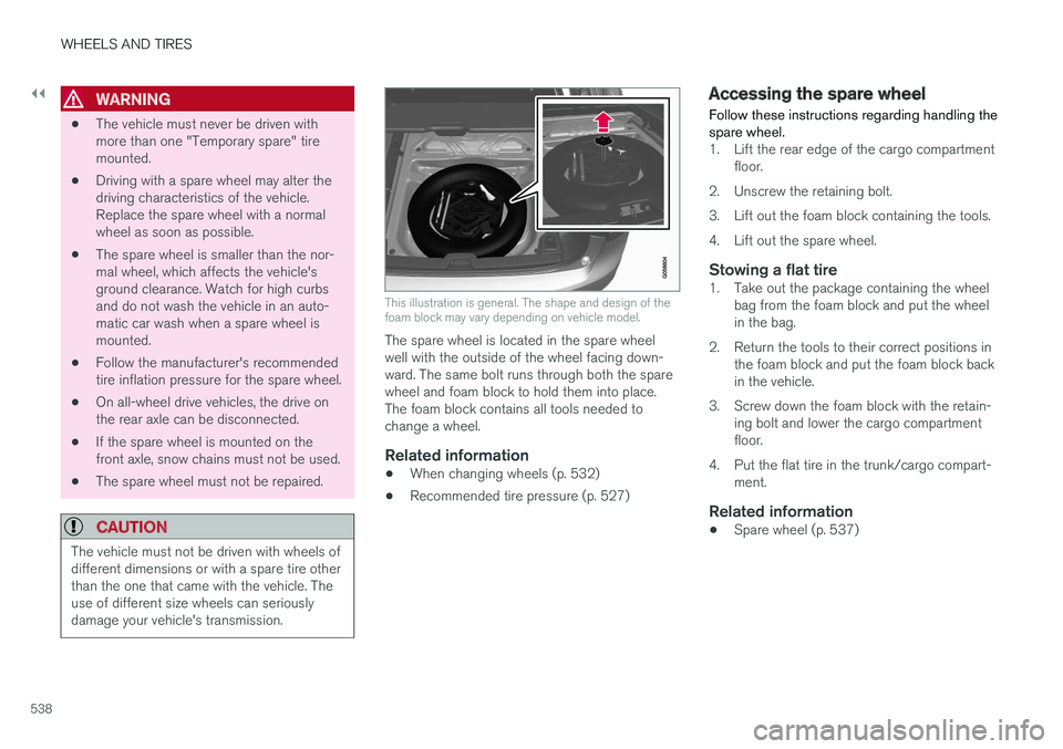
This illustration is general. The shape and design of the foam block may vary depending on vehicle model.
The spare wheel is located in the spare wheel well with the outside of the wheel facing down-ward. The same bolt runs through both the sparewheel and foam block to hold them into place.The foam block contains all tools needed tochange a wheel.
Related information
•When changing wheels (p. 532)
• Recommended tire pressure (p. 527)
Accessing the spare wheel
Follow these instructions regarding handling the spare wheel.
1. Lift the rear edge of the cargo compartment floor.
2. Unscrew the retaining bolt.
3. Lift out the foam block containing the tools.
4. Lift out the spare wheel.
Stowing a flat tire1. Take out the package containing the wheel bag from the foam block and put the wheel in the bag.
2. Return the tools to their correct positions in the foam block and put the foam block backin the vehicle.
3. Screw down the foam block with the retain- ing bolt and lower the cargo compartmentfloor.
4. Put the flat tire in the trunk/cargo compart- ment.
Related information
• Spare wheel (p. 537)