power steering VOLVO XC60 2017 Owner´s Manual
[x] Cancel search | Manufacturer: VOLVO, Model Year: 2017, Model line: XC60, Model: VOLVO XC60 2017Pages: 398, PDF Size: 9.17 MB
Page 5 of 398
3
INSTRUMENTS AND CONTROLS
Instrument overview 66
Information displays – introduction 69
Eco Guide * and Power Meter *
72
Information displays – indicator symbols 73
Information displays – warning symbols 75
My Car – introduction 77
Information displays – ambient tem- perature sensor 78
Information displays – trip odometerand clock 79
Inserting/removing remote key 79
Ignition modes 80
Front seats 81
Front seats – folding backrest *
82
Front seats – power seat 82
Key memory – power driver's seat *
and door mirrors 84
Rear seats – head restraints 85
Rear seats – folding backrest 87
Steering wheel 89
Electrically heated * steering wheel
90
Lighting panel 90
High/low beam headlights 91
Active high beams (AHB) *
92
Tunnel detection (models with the rain sensor * only) 93
Active Bending Lights (ABL)
*
93
Auxiliary lights *
94
Instrument and "theater" lighting 94
Parking lights 95
Rear fog lights 95
Hazard warning flashers 96
Turn signals 97
Front interior lighting 97
Rear interior lighting 98
Home safe lighting 99
Approach lighting 99
Windshield wipers 99
Rain sensor *
100
Windshield washer 101
Tailgate wiper/washer 102
Power windows 102
Power door mirrors 104
Power door mirrors – automatic tilt- ing/retraction 105
Heated windshield *, rear window and
door mirror defrosters 106
Interior rearview mirror 106
Digital compass *
107
Panoramic roof * – introduction
108
Panoramic roof * – operation
109
HomeLink®
Wireless Control Sys-
tem * – introduction 111
HomeLink ®
Wireless Control Sys-
tem * – programming 112
Volvo Sensus 114
Information display – menu controls 115
Information display – menu overview 115
Information display – messages 116
Trip computer – introduction 117
Trip computer – functions, analog instrument panel 118
Trip computer – functions, digitalinstrument panel 121
Trip computer – Supplementaryinformation 123
Trip computer – Trip statistics 124
Page 7 of 398
5
Power tailgate – automatic opening/ closing167
Power tailgate – programming 168
Power tailgate – interruption 168
Power tailgate – manual opening/closing 168
Alarm – general information 169
Alarm indicator 169
Alarm – arming/disarming 170
Alarm signal 170
Alarm – turning off 171
Alarm-related functions 171
DRIVER SUPPORT
Active chassis* (Four C)
174
Stability system – introduction 174
Stability system – operation 175
Stability system – symbols and messages 177
Adjustable steering force *
179
Road Sign Information (RSI) * – intro-
duction 179
Road Sign Information (RSI) – operation 180
Road Sign Information (RSI) – limitations 180
Cruise control (CC) – introduction 181
Cruise control (CC) – engaging and setting speed 181
Toggling between ACC and CC(standard Cruise Control) 182
Cruise control (CC) – deactivating 183
Adaptive Cruise Control – introduction 184
Adaptive Cruise Control – function 185
Adaptive Cruise Control – engaging 187
Adaptive Cruise Control – setting speed 188
Adaptive Cruise Control – settingtime interval 189
Adaptive Cruise Control – deactivating 189
Adaptive Cruise Control – passinganother vehicle 191
Adaptive Cruise Control (ACC) –Queue Assist 191
Radar sensor
193
Adaptive Cruise Control – limitations 194
Adaptive Cruise Control – symbols and messages 196
Adaptive Cruise Control – trouble-shooting 198
Distance Alert – introduction 199
Distance Alert – operation 199
Distance Alert – limitations 200
Distance Alert – symbols and messages 202
City Safety – introduction 203
City Safety – function 204
City Safety – operation 205
City Safety – limitations 205
City Safety – troubleshooting 206
City Safety – symbols and messages 208
City Safety – Laser sensor 209
Collision warning – introduction 210
Collision warning * – function
212
Collision warning * – operation
213
Collision warning * – Cyclist detection
214
Collision warning * – Pedestrian detection
215
Collision warning * – limitations
216
The camera
Page 10 of 398
8
MAINTENANCE AND SERVICING
Maintenance – introduction322
Maintenance – owner maintenance 323
Maintenance – hoisting 324
Onboard Diagnostic System 325
Booking service and repairs 325
Maintenance – opening/closing hood 327
Engine compartment – overview 328
Engine compartment – engine oil 329
Engine compartment – coolant 331
Engine compartment – brake fluid 332
Engine compartment – power steer- ing fluid 333
Bulbs – introduction 334
Bulbs – headlight housing 335
Bulbs – cover 336
Bulbs – low beam, Halogen 337
Bulbs – high beam, Halogen 337
Bulbs – extra high beam 338
Bulbs – front turn signals 338
Bulbs – rear fog lights 339
Bulbs – location of taillight bulbs 339
Bulbs – brake lights and taillights 340
Bulbs – license plate lighting 340
Bulbs – cargo area lighting 340
Bulbs – vanity mirror lighting 341
Bulbs – specifications341
Wiper blades – service position 342
Wiper blades – windshield 342
Wiper blades – tailgate 343
Engine compartment – washer fluid 344
Battery – symbols 345
Battery – handling 345
Battery – maintenance 346
Battery – changing 347
Fuses – introduction 349
Fuses – engine compartment 350
Fuses – glove compartment 353
Fuses – cargo area/trunk 356
Fuses – engine compartment cold zone (Start/Stop only) 357
Washing the car 359
Automatic car wash 360
Polishing and waxing 361
Cleaning the interior 361
Touching up paintwork 363
SPECIFICATIONS
Label information366
Dimensions 369
Weights 372
Engine specifications 374
Oil specifications 375
Oil volume 376
Coolant – specification and volume 377
Transmission oil – specification and volumes 377
Brake fluid – specification and volume 377
Power steering – specification 378
Fuel tank volume – specification andvolume 378
Tire inflation – pressure table 379
Air conditioning – specification andvolume 380
Battery specifications 381
Symbols – general information 382
Warning symbols 382
Indicator symbols 383
Information symbols 384
Information symbols – ceiling console 385
Information symbols – center console 385
Page 70 of 398
||
INSTRUMENTS AND CONTROLS
* Option/accessory, for more information, see Introduction.
68
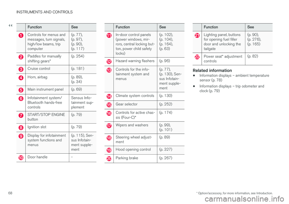
FunctionSee
Controls for menus and messages, turn signals,high/low beams, tripcomputer(p. 77), (p. 97),(p. 90),(p. 117)
Paddles for manually shifting gears *(p. 254)
Cruise control(p. 181)
Horn, airbag(p. 89), (p. 34)
Main instrument panel(p. 69)
Infotainment system/ Bluetooth hands-freecontrolsSensus Info- tainment sup-plement
START/STOP ENGINE button(p. 79)
Ignition slot(p. 79)
Display for infotainment system functions andmenus(p. 115), Sen- sus Infotain-ment supple-ment
Door handle-
FunctionSee
In-door control panels (power windows, mir-rors, central locking but-ton, power child safetylocks)(p. 102), (p. 104),(p. 164),(p. 63)
Hazard warning flashers(p. 96)
Controls for the info- tainment system andmenus(p. 77), (p. 130), Sen-sus Infotain-ment supple-ment
Climate system controls(p. 130)
Gear selector(p. 252)
Controls for active chas- sis (Four-C)*(p. 174)
Wipers and washers(p. 99), (p. 101)
Steering wheel adjust- ment(p. 89)
Hood opening control(p. 327)
Parking brake(p. 267)
FunctionSee
Lighting panel, buttons for opening fuel fillerdoor and unlocking thetailgate(p. 90), (p. 276),(p. 165)
Power seat* adjustment
controls(p. 82)
Related information
• Information displays – ambient temperature sensor (p. 78)
• Information displays – trip odometer andclock (p. 79)
Page 72 of 398
||
INSTRUMENTS AND CONTROLS
* Option/accessory, for more information, see Introduction.
70
Gauges and indicators: digital instrument panel *
Different themes (display alternatives) can be selected for the digital instrument panel:
• Elegance
• Eco
• Performance
To change themes, press the OK button on the
left steering wheel lever and use the thumb wheel to scroll to
Themes. Press OK to confirm
your choice.
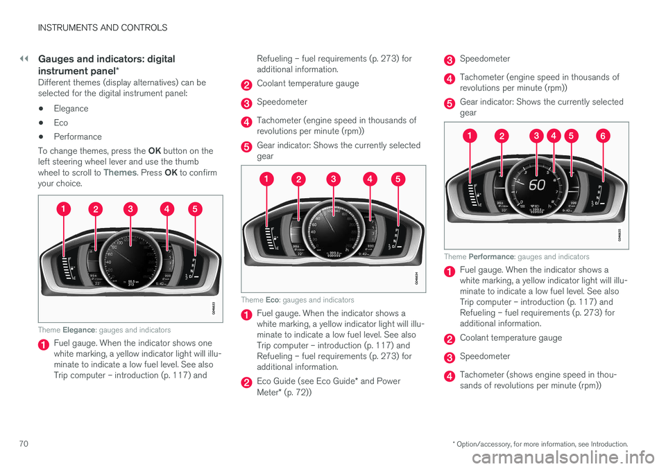
Theme Elegance : gauges and indicators
Fuel gauge. When the indicator shows one white marking, a yellow indicator light will illu-minate to indicate a low fuel level. See alsoTrip computer – introduction (p. 117) and Refueling – fuel requirements (p. 273) foradditional information.
Coolant temperature gauge
Speedometer
Tachometer (engine speed in thousands of revolutions per minute (rpm))
Gear indicator: Shows the currently selected gear
Theme
Eco: gauges and indicators
Fuel gauge. When the indicator shows a white marking, a yellow indicator light will illu-minate to indicate a low fuel level. See alsoTrip computer – introduction (p. 117) andRefueling – fuel requirements (p. 273) foradditional information.
Eco Guide (see Eco Guide * and Power
Meter * (p. 72))
Speedometer
Tachometer (engine speed in thousands of revolutions per minute (rpm))
Gear indicator: Shows the currently selected gear
Theme Performance : gauges and indicators
Fuel gauge. When the indicator shows a white marking, a yellow indicator light will illu-minate to indicate a low fuel level. See alsoTrip computer – introduction (p. 117) andRefueling – fuel requirements (p. 273) foradditional information.
Coolant temperature gauge
Speedometer
Tachometer (shows engine speed in thou- sands of revolutions per minute (rpm))
Page 91 of 398
INSTRUMENTS AND CONTROLS
* Option/accessory, for more information, see Introduction.89
Steering wheel The steering wheel can be adjusted to various positions and has controls for the horn, cruise control*, menus, the infotainment system and
Bluetooth ®
-connected cell phone.
Adjusting
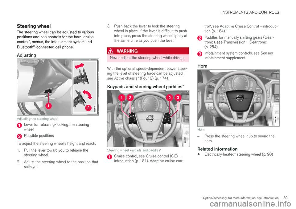
G021138
Adjusting the steering wheel
Lever for releasing/locking the steering wheel
Possible positions
To adjust the steering wheel's height and reach:
1. Pull the lever toward you to release the steering wheel.
2. Adjust the steering wheel to the position that suits you. 3. Push back the lever to lock the steering
wheel in place. If the lever is difficult to push into place, press the steering wheel lightly atthe same time as you push the lever.
WARNING
Never adjust the steering wheel while driving.
With the optional speed-dependent power steer- ing the level of steering force can be adjusted, see Active chassis * (Four C) (p. 174).
Keypads and steering wheel paddles *
Steering wheel keypads and paddles*
Cruise control, see Cruise control (CC) – introduction (p. 181). Adaptive cruise con- trol
*, see Adaptive Cruise Control – introduc-
tion (p. 184).
Paddles for manually shifting gears (Gear- tronic), see Transmission – Geartronic(p. 254).
Infotainment system controls, see Sensus Infotainment supplement.
Horn
Horn
–Press the steering wheel hub to sound the horn.
Related information
• Electrically heated
* steering wheel (p. 90)
Page 118 of 398
INSTRUMENTS AND CONTROLS
116
Information display – messagesThe controls on the left steering wheel lever are used to scroll among messages displayed in theinstrument panel and to confirm selections. When information, indicator or warning symbols illuminate, an explanatory message will be dis-played in the instrument panel.
When a warning (p. 75), information (p. 73) or indicator symbol (p. 73) comes on, a correspond-ing message appears in the information panel. Anerror message is stored in a memory list until thefault is rectified. Press OK to acknowledge and scroll among the
messages.
NOTE
If a warning message appears while you are using the trip computer, the message must be read and confirmed by pressing OK before
the previous activity can be resumed.
MessageDescription
Stop engineAStop and switch off the engine as soon as possible.Serious risk of damage. Con-tact an authorized Volvoworkshop.
Stop safelyAStop and switch off the engine. Serious risk of dam-age. Contact an authorizedVolvo workshop.
Service urgentAHave the vehicle checked by an authorized Volvo work-shop immediately.
Service requiredAHave the vehicle checked by an authorized Volvo work-shop as soon as possible.
See manualARead the owner's manual.
Book time for mainte-nanceTime to book service at an authorized Volvo retailer.
Time for reg- ular mainte-nanceTime for regular service at an authorized Volvo workshop.The timing is determined bythe number of miles driven,number of months since thelast service, engine runningtime.
MessageDescription
Maintenance overdueIf the service intervals are not followed, the warranty doesnot cover any damaged parts.Contact an authorized Volvoworkshop for service.
Temporarily OFFAA function has been tempo- rarily switched off and isreset automatically while driv-ing or after starting again.
Low battery Power savemodeThe audio system is switched off to save current. Chargethe battery.
A There will also be a system-specific part of this message
Related information
• Information displays – introduction (p. 69)
• Information display – menu overview (p. 115)
• Information display – menu controls (p. 115)
Page 156 of 398
||
LOCKS AND ALARM
* Option/accessory, for more information, see Introduction.
154
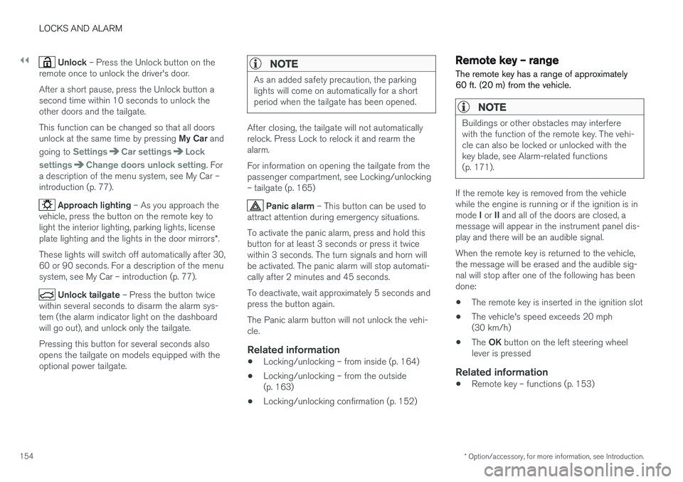
Unlock – Press the Unlock button on the
remote once to unlock the driver's door. After a short pause, press the Unlock button a second time within 10 seconds to unlock theother doors and the tailgate. This function can be changed so that all doors unlock at the same time by pressing My Car and
going to
SettingsCar settingsLock
settings
Change doors unlock setting. For
a description of the menu system, see My Car – introduction (p. 77).
Approach lighting – As you approach the
vehicle, press the button on the remote key to light the interior lighting, parking lights, license plate lighting and the lights in the door mirrors *.
These lights will switch off automatically after 30, 60 or 90 seconds. For a description of the menusystem, see My Car – introduction (p. 77).
Unlock tailgate – Press the button twice
within several seconds to disarm the alarm sys- tem (the alarm indicator light on the dashboardwill go out), and unlock only the tailgate. Pressing this button for several seconds also opens the tailgate on models equipped with theoptional power tailgate.
NOTE
As an added safety precaution, the parking lights will come on automatically for a shortperiod when the tailgate has been opened.
After closing, the tailgate will not automatically relock. Press Lock to relock it and rearm thealarm. For information on opening the tailgate from the passenger compartment, see Locking/unlocking– tailgate (p. 165)
Panic alarm – This button can be used to
attract attention during emergency situations. To activate the panic alarm, press and hold this button for at least 3 seconds or press it twicewithin 3 seconds. The turn signals and horn willbe activated. The panic alarm will stop automati-cally after 2 minutes and 45 seconds. To deactivate, wait approximately 5 seconds and press the button again. The Panic alarm button will not unlock the vehi- cle.
Related information
• Locking/unlocking – from inside (p. 164)
• Locking/unlocking – from the outside(p. 163)
• Locking/unlocking confirmation (p. 152)
Remote key – range The remote key has a range of approximately 60 ft. (20 m) from the vehicle.
NOTE
Buildings or other obstacles may interfere with the function of the remote key. The vehi-cle can also be locked or unlocked with thekey blade, see Alarm-related functions(p. 171).
If the remote key is removed from the vehicle while the engine is running or if the ignition is in mode
I or II and all of the doors are closed, a
message will appear in the instrument panel dis- play and there will be an audible signal. When the remote key is returned to the vehicle, the message will be erased and the audible sig-nal will stop after one of the following has beendone:
• The remote key is inserted in the ignition slot
• The vehicle's speed exceeds 20 mph(30 km/h)
• The
OK button on the left steering wheel
lever is pressed
Related information
• Remote key – functions (p. 153)
Page 177 of 398
DRIVER SUPPORT
}}
175
Traction Control (TC)
This function is designed to help reduce wheel spin at low speeds by transferring power from adrive wheel that begins to lose traction to thewheel on the opposite side of the vehicle (on thesame axle).
Spin Control (SC)
The SC function is designed to help prevent the drive wheels from spinning while the vehicle isaccelerating.
Active Yaw Control (AYC)
This function helps maintain directional stability, for example when cornering, by braking one ormore of the wheels if the vehicle shows a ten-dency to skid or slide laterally.
Corner Traction Control (CTC)
CTC compensates for understeering and helps provide additional stability when acceleratingthrough a curve by preventing the inside wheelfrom spinning. This is particularly useful whenaccelerating on a curving highway on-ramp. CTC is most effective if the stability system's Sport mode is selected. See the section about
Sport mode.
Engine Drag Control (EDC)
EDC helps keep the engine running if the wheels show a tendency to lock, e.g., when shifting downin the Geartronic manual shifting mode or whileusing the engine's braking function on a slippery surface. If the engine were to stop, power steer-ing would not function, making the vehicle moredifficult to steer.
Trailer Stability Assist (TSA)
1
The TSA helps stabilize a vehicle that is towing a trailer when the vehicle and trailer have begun tosway. See Trailer Stability Assist (TSA) (p. 282)for more information. This system is automatically deactivated if the driver selects
Sport mode.
Related information
•Stability system – operation (p. 175)
• Stability system – symbols and messages (p. 177)
• Trailer Stability Assist (TSA) (p. 282)
Stability system – operation
Operation
Sport mode
The stability system is always activated and can- not be switched off.
However, the driver can select Sport mode, which offers more
active driving characteristics. Sport mode can be selected in
the MY CAR menus, see My Car – introduction (p. 77).
In Sport mode, the engine management system
monitors movement of the accelerator pedal and steering wheel for sportier driving by allowingmore lateral movement of the rear wheels beforeESC is activated. Under certain circumstances, such as when driv- ing with snow chains, or driving in deep snow orloose sand, it may be advisable to temporarily use Sport mode for maximum tractive force.
If the driver releases pressure on the accelerator pedal, ETC will also activate to help stabilize thevehicle. To switch to Sport mode:
Sport mode remains active until the driver
switches it off in the menu or until the engine is
1 Included when a Volvo trailer hitch is installed
Page 181 of 398
DRIVER SUPPORT
* Option/accessory, for more information, see Introduction.179
Adjustable steering force*
Steering force increases with the speed of the vehicle to give the driver enhanced sense ofcontrol and stability. At low speed the vehicle iseasy to steer in order to facilitate parking, etc.
Adjustable steering force *Steering force can be changed under MY CAR
Car settingsSteering wheel force.
Select Low, Medium or High. For a description
of the menu system, My Car – introduction (p. 77).
NOTE
This steering force level menu function can- not be accessed when the vehicle is inmotion.
NOTE
In certain situations, the power steering may become too warm and will have to be tempo-rarily cooled down. While this is happening,the power steering effect will be reducedslightly and somewhat more effort may berequired to turn the steering wheel. If this occurs, a message will be displayed in the instrument panel.
Related information
• Active chassis
* (Four C) (p. 174)
Road Sign Information (RSI) * –
introduction
RSI is a feature that helps the driver see road signs with the posted speed limit.
Introduction
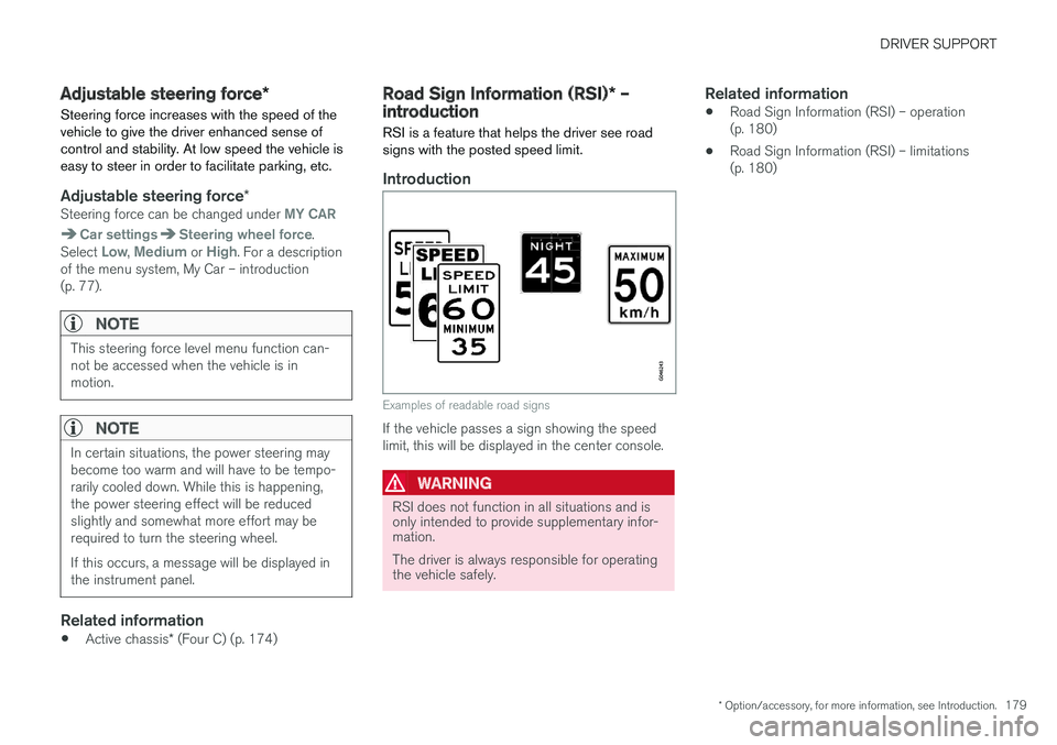
Examples of readable road signs
If the vehicle passes a sign showing the speed limit, this will be displayed in the center console.
WARNING
RSI does not function in all situations and is only intended to provide supplementary infor-mation. The driver is always responsible for operating the vehicle safely.
Related information
• Road Sign Information (RSI) – operation (p. 180)
• Road Sign Information (RSI) – limitations(p. 180)