clock VOLVO XC60 TWIN ENGINE 2020 Owner's Manual
[x] Cancel search | Manufacturer: VOLVO, Model Year: 2020, Model line: XC60 TWIN ENGINE, Model: VOLVO XC60 TWIN ENGINE 2020Pages: 687, PDF Size: 14.65 MB
Page 437 of 687

STARTING AND DRIVING
* Option/accessory.435
Turn the adjustment knob counterclock- wise to the desired adjustment position.
> When the desired position has been
reached, replace the protective rubber cap. Then follow the same procedurefor the second tire.
NOTE
For optimal performance, Volvo recom- mends setting the adjustment knobs to thesame position for each axle.
Recommended positions
Position Front Rear Performance mode adjustmentposition 4adjustmentposition 4
Engineered,factory setting adjustmentposition 10adjustmentposition 10
Comfort mode adjustment position 15adjustmentposition 15
Related information
Hoisting the vehicle (p. 597)
Leveling control
* and suspension (p. 430)
Low Speed Control
The low-speed function (LSC 10
) facilitates
and improves control and traction on rough roads and slippery surfaces, e.g. when towinga trailer on grass or up boat ramps. The function is included in the
Off Road drive
mode.
Low Speed Control is designed for driving on rough roads and when towing trailers at lowspeeds, up to approximately 40 km/h (25mph). When driving at low speeds, LSC prioritizes low gears and all-wheel drive to help avoidwheel spin and improve traction on all wheels.The accelerator pedal will be less responsiveto improve traction and speed control at lowspeeds. The function is activated together with Hill Descent Control (HDC 11
), which makes it pos-
sible to control speed going down steep hills using the accelerator pedal and reduces theneed to use the brake pedal. The systemmakes it possible to maintain a low and uni-form speed when driving down steep hills.
NOTE
When LSC with HDC is activated in theOff Road drive mode, the feel of the accel-
erator pedal and engine response will change.
NOTE
This drive mode is not designed to be used for normal street driving.
NOTE
The function is deactivated when driving at high speeds and must be reactivated atlower speeds if so desired.
Related information
Activating and deactivating Low Speed Control using the function button (p. 436)
Changing drive mode (p. 428)
Hill Descent Control (p. 436)
All Wheel Drive (AWD) (p. 421)
10
Low Speed Control
11 Hill Descent Control
Page 454 of 687

||
STARTING AND DRIVING
4521. Put the ignition in mode
0.
2. Make sure the auxiliary battery (the bat- tery used to jump start the discharged battery) has a voltage of 12 volts.
3. If the auxiliary battery is in another vehicle, turn off that vehicle's engine and makesure that the vehicles are not touchingeach other.
4. Clamp the red jumper cable onto the auxil- iary battery's positive (+) terminal (1).
CAUTION
Connect the jump cable carefully to pre- vent short circuits with other componentsin the engine compartment.
5. Fold back the cover over your vehicle's positive (+) jump start terminal (2).
6. Clamp the other end of the red jumper cable to your vehicle's positive (+) jump start terminal (2).
7. Clamp the black jumper cable onto the auxiliary battery's negative (-) terminal (3).
8. Clamp the other end of the black jumper cable to your vehicle's negative (-) groundpoint (4). 9. Make sure the jumper cables are securely
attached to help prevent sparks whilejump starting.
10. Start the engine of the assisting vehicle and let it run for a few minutes at a higheridling speed than normal, about1500 rpm.
11. Start your vehicle's engine. If the engine does not start, allow an additional 10minutes of charging time and then try tostart the engine again.
NOTE
When the engine is started under normal conditions, the vehicle's electrical drivemotor is prioritized – the gasoline engineremains off. This means that after the startknob has been turned clockwise, the elec-tric motor has "started" and the vehicle isready to be driven. Start of the electricmotor is indicated by the indicator lights onthe instrument panel going out and its pre-selected theme illuminating.
CAUTION
Do not touch the connections between the cable and the vehicle during the startattempt. Risk of sparking.
12. Remove the jumper cables in the reverseorder ‒ first the black cables and then the
red cables. Make sure that none of the clamps of the black jumper cables come into contactwith either vehicle's positive (+) jump startterminals or either of the red jumpercable's connected clamps.
WARNING
PROPOSITION 65 WARNING! Battery
posts, terminals, and related accessories contain lead and lead compounds, chemi-cals known to the state of California tocause cancer and reproductive harm. Washhands after handling.
WARNING
Batteries generate hydrogen gas, which is flammable and explosive.
Do not connect the jumper cable toany part of the fuel system or to anymoving parts. Avoid touching hotmanifolds.
Battery fluid contains sulfuric acid. Donot allow battery fluid to contact eyes,skin, fabrics or painted surfaces.
If contact occurs, flush the affectedarea immediately with water. Obtain
Page 557 of 687

WHEELS AND TIRES
* Option/accessory.555
5. Using the lug wrench, screw the towing
eye into place as far as possible according to the instructions.
CAUTION
The towing eyelet must be screwed into the lug wrench * as far as possible.
6. Remove the plastic covers from the wheel
bolts using the designated tool.
7. With the vehicle still on the ground, use the lug wrench/towing eye to loosen the wheel bolts ½-1 turn by pressing down-ward (counterclockwise). 8. When hoisting the vehicle, it is important
that the jack or garage lift arms are posi-tioned on the designated points under thevehicle. The triangle markings on the plas-tic cover indicate where the jack attach-ment points/lifting points are located.There are two jack attachment points oneach side of the vehicle. There is a groovefor the jack at each attachment point.
9. Position the jack under the attachmentpoint being used, ensuring that the sur- face is firm, flat and not slippery. 10. Crank it up until it is properly aligned and
it is in contact with the vehicle's jackattachment point. Make sure the top ofthe jack (or the garage lift arms) is cor-rectly positioned in the attachment point,with the bump on the top of the jack in therecess in the attachment point and thebase positioned vertically under theattachment point.
11. Turn the jack so that the crank is as far as possible from the side of the vehicle,which will position the jack's arms per-pendicular to the vehicle's direction ofmovement.
12. Raise the vehicle until the wheel to be changed can move freely. Unscrew thewheel bolts and lift off the wheel.
Related information
Leveling control settings
* (p. 433)
When changing wheels (p. 552)
Hoisting the vehicle (p. 597)
Jack
* (p. 553)
Attaching and removing the towing eyelet(p. 461)
Installing a wheel (p. 556)
Page 578 of 687

||
LOADING, STORAGE AND PASSENGER COMPARTMENT
* Option/accessory.
576
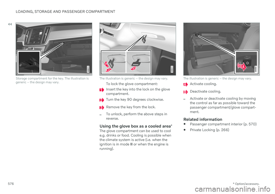
Storage compartment for the key. The illustration is generic – the design may vary.The illustration is generic – the design may vary.
To lock the glove compartment:
Insert the key into the lock on the glove compartment.
Turn the key 90 degrees clockwise.
Remove the key from the lock.
–To unlock, perform the above steps in reverse.
Using the glove box as a cooled area *The glove compartment can be used to cool e.g. drinks or food. Cooling is possible when the climate system is active (i.e. when the ignition is in mode II or when the engine is
running).
The illustration is generic – the design may vary.
Activate cooling.
Deactivate cooling.
–Activate or deactivate cooling by moving the control as far as possible toward thepassenger compartment/glove compart-ment.
Related information
Passenger compartment interior (p. 570)
Private Locking (p. 266)
Page 643 of 687

MAINTENANCE AND SERVICE
}}
* Option/accessory.641
Automatic car washes
The vehicle should be washed as soon as it becomes dirty. The longer the dirt remains,the more difficult it will be to keep the vehicleclean. It could also lead to paint damage.
Washing your vehicle in an automatic car wash is a fast and easy way to keep your vehi-cle clean, but it does not reach all areas of thevehicle. Volvo recommends washing yourvehicle by hand or supplementing automaticcar washes with a hand wash.
NOTE
Volvo recommends not washing the vehi- cle in an automatic car wash during thefirst few months; the paintwork on newvehicles takes some time to fully harden.
CAUTION
Before driving the vehicle into a car wash, deactivate the Automatic Braking whenStationary and Automatic Parking BrakeApplication functions. If the functions arenot deactivated, the brake system willseize when the vehicle is stationary and thevehicle will not be able to roll.
CAUTION
For automatic car washes in which the vehicle is pulled forward on rolling wheels:
1. Before washing the vehicle, make sure that the automatic rain sensor is deac- tivated. If it is not deactivated andinadvertently starts, the wiper armscould be damaged.
2. To help prevent damage from the auto- matic car wash machinery, make surethat the door mirrors are folded in,antennas retracted or removed, andany auxiliary lights secured.
3. Drive into the automatic car wash.
4. Turn off the "Automatic Braking when Stationary" function using the
but-
ton in the tunnel console.
5. Turn off the "Automatic Parking Brake Application" function in the center dis- play's Top view.
6. Turn off the engine by turning the start knob in the tunnel console clockwise.Hold the knob in position for at least2 seconds.
The vehicle is now ready for the automaticcar wash.
CAUTION
The system will automatically change to P
mode if the above steps are not followed. In P mode, the wheels are locked, which
they should not be when the vehicle isbeing washed in a car wash.
NOTE
Keep in mind that if the vehicle is equipped with the keyless locking and unlocking function *, the doors and tailgate/trunk lid
may open when washing the vehicle if the remote key is within range.
Related information
Cleaning the exterior (p. 638)
Polishing and waxing (p. 638)
Hand washing (p. 639)
High-pressure washing (p. 642)
Cleaning the wiper blades (p. 642)
Cleaning exterior plastic, rubber and trim components (p. 643)
Cleaning rims (p. 644)
Corrosion protection (p. 644)
Auto-hold brakes (p. 414)
Page 671 of 687

INDEX
669
keyboard 129
messages 143, 144
operation 115, 118, 122, 127
overview 113
settings 135, 136
switch off and change volume 134
symbols in status bar 127
views 118
Central locking 257
Change of owner 137
Changing a wheel 552 Charge vehicle function 441
Charge level vehicle function 441
Charging hybrid battery 385 opening and closing the charging
door 390
start charging 390
Status 392, 393, 394
stop charging 396
Charging cable 387
Charging current 387
Checking engine oil level 603
Child restraints 65, 67 booster cushions 74
convertible seats 71
infant seats 69
integrated booster cushion 78
ISOFIX/LATCH anchors 77
lower attachment points 76
recalls and registration 67
top tether anchors 75
Child safety 65
Child safety locks 259
Circuit breaker 389
City Safety 318 braking for oncoming vehicles 327
crossing traffic 324
delayed evasive maneuver 327
detecting obstacles 322
evasive maneuver 326
limitations 328
limitations for evasive maneuvers 326
limitations in crossing traffic 325
setting warning distance 321
sub-functions 319
Symbols and messages 331
Cleaning 635, 637 automatic car wash 641
car wash 638, 639, 641, 642, 643, 644
center display 633
Seat belts 635
textile upholstery 633, 635, 636upholstery 633, 635, 636, 637
wheels 644
Cleaning wheels 644
Cleaning wiper blades 642
Clean Zone 207
Clean Zone Interior Package 208
Climate 204 auto-regulation 219
blower control 222
parking 225
perceived temperature 205
Sensors 204
temperature control 223, 224
voice control 205
zones 204
Climate controls 215 center display 215
rear seat 215
Climate system 204, 215 Refrigerant 664
repairs 599
Clock, setting 96
Collision 44, 49, 54, 63 Collision warner crossing traffic rear 337
see City Safety 318