VOLVO XC70 2014 Owner´s Manual
Manufacturer: VOLVO, Model Year: 2014, Model line: XC70, Model: VOLVO XC70 2014Pages: 394, PDF Size: 11.55 MB
Page 51 of 394

01 Safety
Top tether anchors01
49
Child restraint anchorages
Your Volvo is equipped with child restraint top tether anchorages in the rear seat. Theyare located on the rear side of the backrests.
Securing a child seat1. Place the child restraint on the rear seat.
2. Route the top tether strap under the headrestraint and attach it to the anchor.
3. Attach lower tether straps to the lower ISOFIX/LATCH anchors. If the child restraint is not equipped with lower tetherstraps, or the restraint is used in the cen-ter seating position, follow instructions forsecuring a child restraint using the Auto-matic Locking Retractor seat belt (seepage 38). 4. Firmly tension all straps. Refer also to the child seat manufacturer's instructions for information on securing thechild seat.
NOTE
On models equipped with the optional cargo area cover, this cover should beremoved before a child seat is attached tothe child restraint anchors.
WARNING
•
Always refer to the recommendations made by the child restraint manufac-turer.
• Volvo recommends that the top tetheranchors be used when installing a for-ward-facing child restraint.
• Never route a top tether strap over thetop of the head restraint. The strapshould be routed beneath the headrestraint.
• Child restraint anchorages aredesigned to withstand only thoseloads imposed by correctly fitted childrestraints. Under no circumstances arethey to be used for adult seat belts orharnesses. The anchorages are notable to withstand excessive forces onthem in the event of collision if full har-ness seat belts or adult seat belts areinstalled to them. An adult who uses abelt anchored in a child restraintanchorage runs a great risk of suffer-ing severe injuries should a collisionoccur.
• Do not install rear speakers thatrequire the removal of the top tetheranchors or interfere with the properuse of the top tether strap.
Page 52 of 394
01 Safety
Integrated booster cushion* 01
50* Option/accessory, for more information, see Introduction.
Integrated two-stage booster cushion 1
Volvo's optional integrated booster cushions are located in the outboard seating positions.These booster cushions have been speciallydesigned to help safeguard children in therear seat. They should be stowed (foldeddown into the seat cushion) when not in use.When using an integrated booster cushion,the child must be secured with the vehicle'sthree-point seat belt.
Use these booster cushions only with children whose weight isbetween: • Stage 1: 48 – 80 lbs (22 – 36 kg)
• Stage 2: 33 – 55 lbs (15 – 25 kg)
and whose height is between:• Stage 1: 45 – 55 in. (115 – 140 cm)
• Stage 2: 37 – 47 in. (95 – 120 cm)
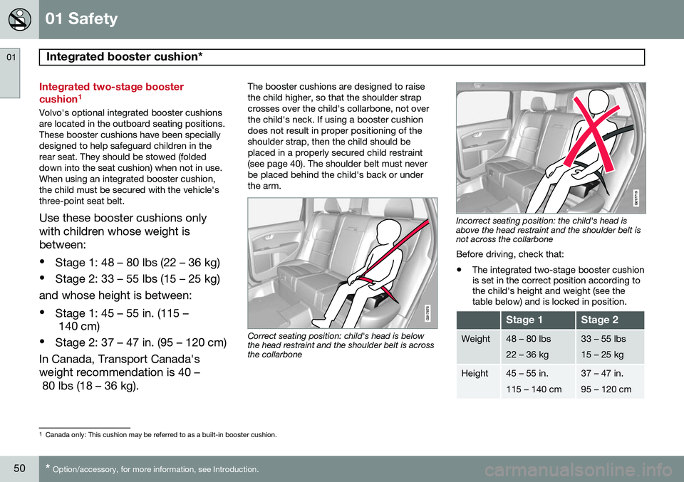
In Canada, Transport Canada's weight recommendation is 40 – 80 lbs (18 – 36 kg). The booster cushions are designed to raise the child higher, so that the shoulder strapcrosses over the child's collarbone, not overthe child's neck. If using a booster cushiondoes not result in proper positioning of theshoulder strap, then the child should beplaced in a properly secured child restraint(see page 40). The shoulder belt must neverbe placed behind the child's back or underthe arm.
G017875
Correct seating position: child's head is below the head restraint and the shoulder belt is acrossthe collarbone
G017719
Incorrect seating position: the child's head is above the head restraint and the shoulder belt isnot across the collarbone Before driving, check that:
• The integrated two-stage booster cushion is set in the correct position according tothe child's height and weight (see thetable below) and is locked in position.
Stage 1Stage 2
Weight48 – 80 lbs 22 – 36 kg33 – 55 lbs 15 – 25 kg
Height45 – 55 in. 115 – 140 cm37 – 47 in. 95 – 120 cm
1
Canada only: This cushion may be referred to as a built-in booster cushion.
Page 53 of 394
01 Safety
Integrated booster cushion*01
}}
* Option/accessory, for more information, see Introduction.51
•
That the seat belt is properly positioned and is taut.
• The shoulder section of the seat belt isacross the child's collarbone, not over theneck.
• The lap section of the seat belt is acrossthe child's hips and not the abdomen.
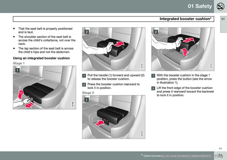
Using an integrated booster cushion
Stage 1G017697
Pull the handle (1) forward and upward (2) to release the booster cushion.
Press the booster cushion rearward to lock it in position.
Stage 2
G017784
With the booster cushion in the stage 1 position, press the button (see the arrowin illustration 1).
Lift the front edge of the booster cushion and press it rearward toward the backrestto lock it in position.
Page 54 of 394
01 Safety
Integrated booster cushion* 01
52* Option/accessory, for more information, see Introduction.
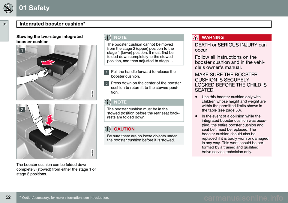
Stowing the two-stage integrated booster cushion
The booster cushion can be folded down completely (stowed) from either the stage 1 orstage 2 positions.
NOTE
The booster cushion cannot be moved from the stage 2 (upper) position to thestage 1 (lower) position. It must first befolded down completely to the stowedposition, and then adjusted to stage 1.
Pull the handle forward to release the booster cushion.
Press down on the center of the booster cushion to return it to the stowed posi-tion.
NOTE
The booster cushion must be in the stowed position before the rear seat back-rests are folded down.
CAUTION
Be sure there are no loose objects under the booster cushion before it is stowed.
WARNING
DEATH or SERIOUS INJURY can occur Follow all instructions on the booster cushion and in the vehi-cle's owner's manual. MAKE SURE THE BOOSTER CUSHION IS SECURELYLOCKED BEFORE THE CHILD ISSEATED. • Use this booster cushion only with children whose height and weight arewithin the permitted limits shown inthe table (see page 50).
• In the event of a collision while theintegrated booster cushion was occu-pied, the entire booster cushion andseat belt must be replaced. Thebooster cushion should also bereplaced if it is badly worn or damagedin any way. This work should be per-formed by a trained and qualifiedVolvo service technician only.
Page 55 of 394

01 Safety
Child safety locks01
* Option/accessory, for more information, see Introduction.53
Child safety locks
G021077
Child safety locks – rear doorsThe controls are located on the rear door jambs. Use the remote control's key blade ora screwdriver to adjust these controls.
The rear doors can only be opened from the outside when the slot is in the hori-zontal position.
The rear doors can be opened from the inside when the slot is in the vertical posi-tion.
Power child safety locks and disengaging rear door windows*
Driver's door control panel
The power child safety locks can be acti- vated/deactivated when the remote key is inmode I (see page 87) or higher. Activation/
deactivation can be done up to 2 minutesafter the engine has been switched off (if nodoor has been opened). To activate the child safety locks:
1. Put the ignition in mode I or higher or
start the engine.
2. Press the button on the driver's door con- trol panel (see the illustration). >
Rear child locks Activated will be
displayed in the instrument panel and the indicator light in the button will illu- minate when the function is activated.
When the child safety locks are activated:
• The rear door windows can only be opened from the driver's door controlpanel
• The rear doors cannot be opened fromthe inside
The child safety locks' current setting is stored when the engine is switched off. Ifthese locks were activated when the enginewas switched off, they will also be activewhen the engine is restarted.
Page 56 of 394
54
Remote key and key blade..................................................................... 56 Private locking ........................................................................................ 65Keyless drive........................................................................................... 66Locks....................................................................................................... 69Alarm....................................................................................................... 72
Page 57 of 394
L O C K S A N D A L A R M
Page 58 of 394

02 Locks and alarm
Remote key and key blade
02
56
Introduction
Two remote keys or optional Personal Car Communicators (PCC) are provided with yourvehicle. They enable you to unlock the doorsand tailgate, and also function as ignitionkeys to start the vehicle or operate electricalcomponents. The remote keys containdetachable metal key blades for manuallylocking or unlocking the driver's door and theglove compartment. The visible ends of thesekey blades are unique to make it easier toidentify "your" remote key. Up to six remotescan be programmed for use on the samevehicle. The PCCs have enhanced functionality com- pared with the standard remote key.
NOTE
In the remainder of this chapter, all refer- ences to the remote key also pertain to thePCC unless otherwise stated.
WARNING
Never leave the remote key in the ignition slot if children are to remain in the vehicle.
See page 86 for more information on the various ignition modes.
Detachable key bladeEach remote key or PCC contains a detacha-ble metal key blade for mechanically lockingor unlocking the driver's door and the glovecompartment, and to enable the private lock-ing function. See page 62 for more informa-tion on the key blade and page 65 for infor-mation on the private locking function. Thekey blades have a unique code, which is usedif new ones need to be produced. This codeis available at an authorized Volvo retailer. The visible ends of these key blades are unique to make it easier to identify "your"remote key.
Loss of a remote keyIf either of the remote keys is lost, the othershould be taken with the car to a Volvoretailer. As an anti-theft measure, the code ofthe lost remote key must be erased from thesystem.
NOTE
Additional or duplicate remote control keys can be obtained from any AuthorizedVolvo Retailer. You can also obtain additional or duplicate remote control keys from certain inde-pendent repair facilities and locksmithsthat are qualified to make remote controlkeys. Each key must be programmed towork with your vehicle. California Only: A list of independent repair facilities and/or locksmiths known to Volvo that can cutand code replacement keys can be found:
• on the Volvo website at http://www.volvocars.com/us/keys
• by calling Volvo Customer Care at1-800-458-1552
The number of registered keys for the vehicle can be found by pressing
MY CAR and going
into
SettingsInformationNumber of
keys. See page 199 for a description of the
menu system. USA-5WK49264FCC ID:KR55WK49264 + Siemens VDO 5WK49236 FCC ID:KR55WK49236, 5WK49266
Page 59 of 394

02 Locks and alarm
Remote key and key blade
02
* Option/accessory, for more information, see Introduction.57
FCC ID:KR55WK49266 + Siemens VDO 5WK49233 FCC ID:KR55WK49233This device complies with part 15 of the FCC rules and RSS-210. Operation is subject tothe following conditions: (1) This device maynot cause harmful interference, and (2) thisdevice must accept any interferencereceived, including interference that maycause undesired operation. Canada-5WK49264IC:267T-5WK49264 + Siemens VDO 5WK49236 IC:267T-5WK49236, 5WK49266IC:267T-5WK49266 + Siemens VDO 5WK49233 IC:267T-5WK49233Operation is subject to the following condi- tions: (1) this device may not cause interfer-ence, and (2) this device must accept anyinterference, including interference that maycause undesired operation of the device.
Key memory: door mirrors and driver's seat
The position of the side door mirrors, power driver's seat* and the selected instrument panel theme
1
are stored in the remote keys
when the vehicle is locked. The next time the
driver's door is unlocked with the same
remote key and the door is opened within 2 minutes , the power driver's seat and side
door mirrors will automatically move to theposition that they were in when the doorswere most recently locked with the sameremote key. If the seat/mirrors have not beenreadjusted since the vehicle was locked, theywill already be in the position stored in thatparticular remote key and will not move. Seepage 89 for more information. See alsopage 90 for more information on this fea-ture. This feature can be activated or deactivated in the vehicle's menu by pressing MY CAR
and going into
SettingsCar settingsCar key memory. See page 199 for a
description of the menu system. See also page 66 for information regarding vehicles with the optional keyless drive.
Confirmation when locking/unlocking the vehicle
Settings can be made in the menu system for audible and visual confirmation when thevehicle has been locked or unlocked. Withthese functions activated, the following willoccur when the vehicle is locked/unlocked:
Locking confirmation
• The turn signals flash once, an audible signal sounds and the door mirrors willfold* in.
Confirmation will only be given when all doors and the tailgate are properly closed andlocked.
NOTE
If you do not receive confirmation when locking the vehicle, check whether a dooror the tailgate is ajar, or if this feature hasbeen turned off in the menu.
Unlocking confirmation
• The turn signals will flash twice and the door mirrors will fold* out.
Making a settingDifferent alternatives for locking/unlocking confirmation can be selected in the menus by
1
Optional digital instrument panel only
Page 60 of 394

02 Locks and alarm
Remote key and key blade
02
58
pressing MY CAR on the center console con-
trol panel. • To activate visual confirmation: go to
SettingsCar settingsLight
settings and select Door lock
confirmation light and/or Unlock
confirmation light by pressing OK/
MENU .
• To activate audible confirmation: go to
SettingsCar settingsLock
settings and select Audible
confirmation by pressing OK/MENU.
See page 199 for a description of the menu system.
Immobilizer (start inhibitor)Each of the keys supplied with your vehiclecontains a coded transponder. The code inthe key is transmitted to an antenna in theignition slot where it is compared to the codestored in the start inhibitor module. The vehi-cle will start only with a properly coded key. Ifyou misplace a key, take the other keys to atrained and qualified Volvo service technicianfor reprogramming as an anti-theft measure.The following messages (which may appearin the instrument panel display) are related tothe immobilizer:
MessageMeaning
Insert car keyRemote key not recognized during start. Try to start thevehicle again.
Car key not foundPCC with keyless drive only. Remote key not recognizedduring start. Try to start thevehicle again. If the problem continues, insert the remote key intothe ignition slot and try tostart the vehicle again.
Immobil- izer TrystartagainRemote key fault during start. Contact an authorizedVolvo workshop.
CAUTION
Never use force when inserting the remote key in the ignition slot. The vehicle cannotbe started if the transponder is damaged.
USA–FCC ID: LTQWFS 125VO This device complies with part 15 of the FCC rules. Operation is subject to the followingcondition: (1) This device may not causeharmful interference, and (2) this device must accept any interference received, includinginterference that may cause undesired opera-tion. Canada–IC: 3659A-WFS125VOOperation is subject to the following condi- tions: (1) this device may not cause interfer-ence, and (2) this device must accept anyinterference, including interference that maycause undesired operation of the device. See page 120 for information on starting the vehicle.
Replacing the battery in the remote keyThe batteries should be replaced if:
• The information symbol illuminates and
Low battery in remote control. Please change batteries. is shown in the dis-
play and/or
• if the locks do not react after several attempts to unlock or lock the vehicle.
NOTE
The remote key's range is normally approximately 60 ft (20 m) from the vehi-cle.
See page 62 for information about replacing the battery.