instrument panel VOLVO XC70 2015 Owner´s Manual
[x] Cancel search | Manufacturer: VOLVO, Model Year: 2015, Model line: XC70, Model: VOLVO XC70 2015Pages: 408, PDF Size: 11.26 MB
Page 81 of 408
03 Your driving environment
Instruments and controls
03
}}
* Option/accessory, for more information, see Introduction.79
FunctionPage
Controls for menus and messages, turn signals,high/low beams, tripcomputer209, 104,99, 225
Paddles for manually shifting gears*129
Cruise control156
Horn, airbag97, 22
Main instrument panel79
Infotainment system/ Bluetooth hands-freecontrols240, 269
START/STOP ENGINE button88
Ignition slot88
Display for infotainment system functions andmenus240, 207
Hazard warning flashers104
Door handle–
FunctionPage
In-door control panels (power windows, mirrors,central locking button,power child safety locks)110, 112,71,54
Controls for the infotain- ment system and menus209, 240, 218
Climate system controls218
Gear selector127
Controls for active chas- sis (Four-C)*232
Wipers and washers107, 108
Steering wheel adjust- ment97
Parking brake144
Hood opening control344
Power seat* adjustment controls90
Lighting panel, buttons for opening fuel fillerdoor and unlocking thetailgate99, 290, 72
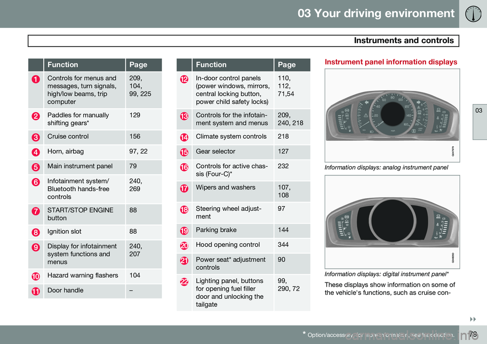
Instrument panel information displays
Information displays: analog instrument panel
Information displays: digital instrument panel* These displays show information on some of the vehicle's functions, such as cruise con-
Page 82 of 408
03 Your driving environment
Instruments and controls
03
80* Option/accessory, for more information, see Introduction.
trol, the trip computer and messages. The information is shown with text and symbols. More detailed information can be found in the descriptions of the functions that use theinformation displays.
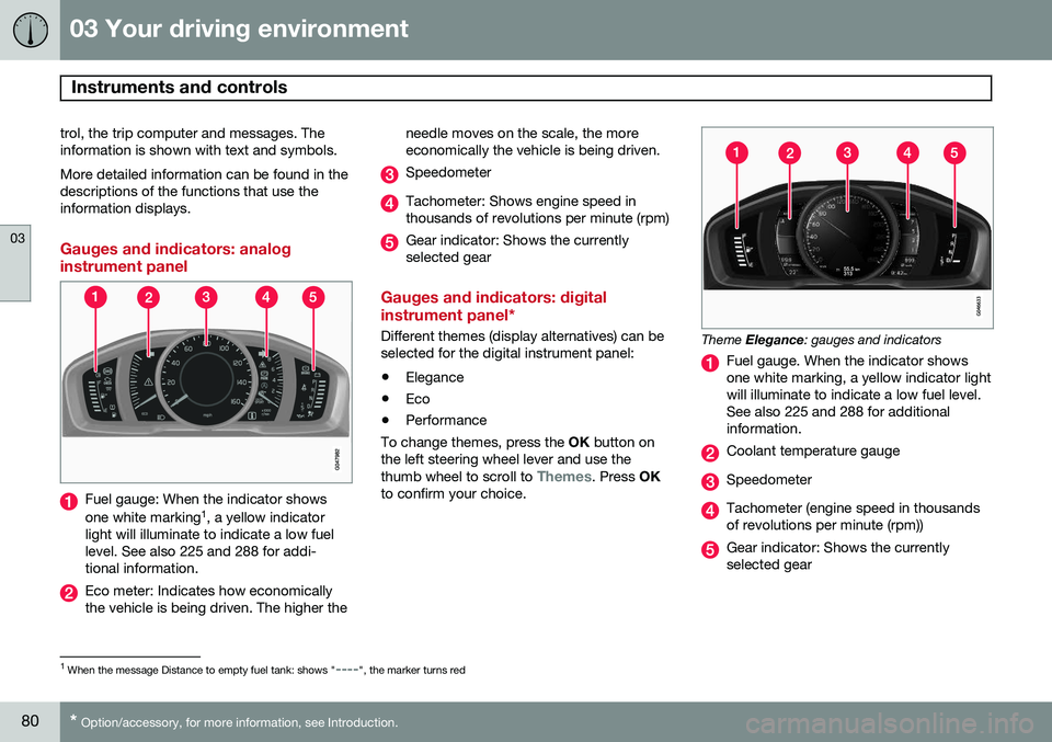
Gauges and indicators: analog instrument panel
Fuel gauge: When the indicator shows one white marking 1
, a yellow indicator
light will illuminate to indicate a low fuel level. See also 225 and 288 for addi-tional information.
Eco meter: Indicates how economically the vehicle is being driven. The higher the needle moves on the scale, the moreeconomically the vehicle is being driven.
Speedometer
Tachometer: Shows engine speed in thousands of revolutions per minute (rpm)
Gear indicator: Shows the currently selected gear
Gauges and indicators: digital instrument panel*
Different themes (display alternatives) can be selected for the digital instrument panel: •
Elegance
• Eco
• Performance
To change themes, press the OK button on
the left steering wheel lever and use the thumb wheel to scroll to
Themes. Press OK
to confirm your choice.
Theme Elegance : gauges and indicators
Fuel gauge. When the indicator shows one white marking, a yellow indicator lightwill illuminate to indicate a low fuel level.See also 225 and 288 for additionalinformation.
Coolant temperature gauge
Speedometer
Tachometer (engine speed in thousands of revolutions per minute (rpm))
Gear indicator: Shows the currently selected gear
1
When the message Distance to empty fuel tank: shows "----", the marker turns red
Page 83 of 408
03 Your driving environment
Instruments and controls
03
}}
81
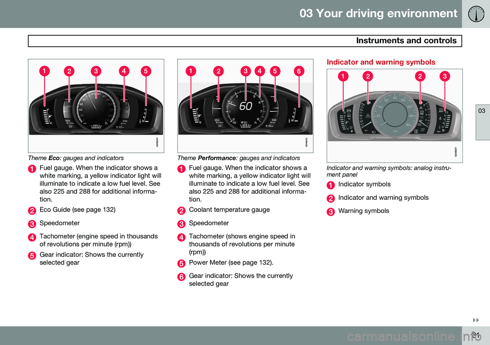
Theme Eco: gauges and indicators
Fuel gauge. When the indicator shows a white marking, a yellow indicator light willilluminate to indicate a low fuel level. Seealso 225 and 288 for additional informa-tion.
Eco Guide (see page 132)
Speedometer
Tachometer (engine speed in thousands of revolutions per minute (rpm))
Gear indicator: Shows the currently selected gear
Theme Performance : gauges and indicators
Fuel gauge. When the indicator shows a white marking, a yellow indicator light willilluminate to indicate a low fuel level. Seealso 225 and 288 for additional informa-tion.
Coolant temperature gauge
Speedometer
Tachometer (shows engine speed in thousands of revolutions per minute(rpm))
Power Meter (see page 132).
Gear indicator: Shows the currently selected gear
Indicator and warning symbols
Indicator and warning symbols: analog instru- ment panel
Indicator symbols
Indicator and warning symbols
Warning symbols
Page 84 of 408
03 Your driving environment
Instruments and controls
03
82* Option/accessory, for more information, see Introduction.
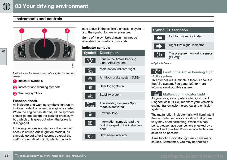
Indicator and warning symbols: digital instrument panel
Indicator symbols
Indicator and warning symbols
Warning symbols
Function checkAll indicator and warning symbols light up in ignition mode II or when the engine is started.
When the engine has started, all the symbolsshould go out except the parking brake sym-bol, which only goes out when the brake isdisengaged. If the engine does not start or if the function check is carried out in ignition mode II, all
symbols go out after 5 seconds except themalfunction indicator light, which may indi- cate a fault in the vehicle's emissions system,and the symbol for low oil pressure. Some of the symbols shown may not be available in all markets or models.
Indicator symbols
SymbolDescription
Fault in the Active Bending Light (ABL)*system
Malfunction indicator light
Anti-lock brake system (ABS)
Rear fog lights on
Stability system
The stability system's Sport mode is activated
Low fuel level
Information symbol, read the text displayed in the instrumentpanel
High beam indicator
SymbolDescription
Left turn signal indicator
Right turn signal indicator
Tire pressure monitoring sensor (TPMS)
A
A
Option in Canada
Fault in the Active Bending Light
(ABL) system
This symbol will illuminate if there is a fault in the ABL system. See page 102 for moreinformation about this system.
Malfunction Indicator Light
As you drive, a computer called On-Board Diagnostics II (OBDII) monitors your vehicle'sengine, transmission, electrical and emissionsystems. The malfunction indicator light will illuminate if the computer senses a condition that poten-tially may need correcting. When this hap-pens, please have your vehicle checked by atrained and qualified Volvo service technicianas soon as possible. A malfunction indicator light may have many causes. Sometimes, you may not notice a
Page 86 of 408
03 Your driving environment
Instruments and controls
03
84
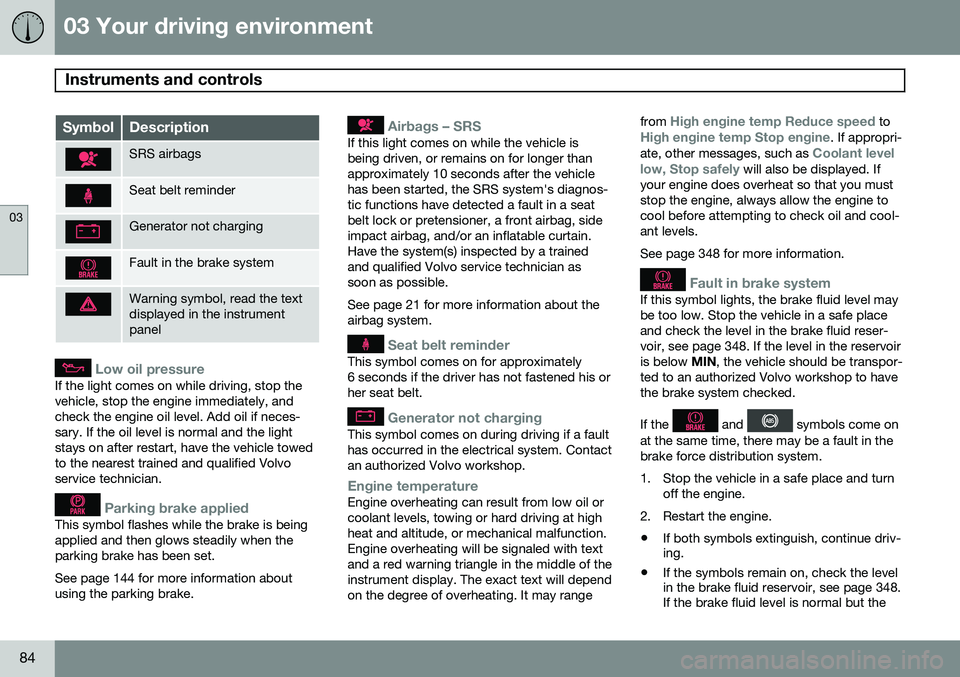
SymbolDescription
SRS airbags
Seat belt reminder
Generator not charging
Fault in the brake system
Warning symbol, read the text displayed in the instrumentpanel
Low oil pressure
If the light comes on while driving, stop the vehicle, stop the engine immediately, andcheck the engine oil level. Add oil if neces-sary. If the oil level is normal and the lightstays on after restart, have the vehicle towedto the nearest trained and qualified Volvoservice technician.
Parking brake applied
This symbol flashes while the brake is being applied and then glows steadily when theparking brake has been set. See page 144 for more information about using the parking brake.
Airbags – SRS
If this light comes on while the vehicle is being driven, or remains on for longer thanapproximately 10 seconds after the vehiclehas been started, the SRS system's diagnos-tic functions have detected a fault in a seatbelt lock or pretensioner, a front airbag, sideimpact airbag, and/or an inflatable curtain.Have the system(s) inspected by a trainedand qualified Volvo service technician assoon as possible. See page 21 for more information about the airbag system.
Seat belt reminder
This symbol comes on for approximately 6 seconds if the driver has not fastened his orher seat belt.
Generator not charging
This symbol comes on during driving if a fault has occurred in the electrical system. Contactan authorized Volvo workshop.
Engine temperatureEngine overheating can result from low oil or coolant levels, towing or hard driving at highheat and altitude, or mechanical malfunction.Engine overheating will be signaled with textand a red warning triangle in the middle of theinstrument display. The exact text will dependon the degree of overheating. It may rangefrom
High engine temp Reduce speed toHigh engine temp Stop engine. If appropri-
ate, other messages, such as Coolant level
low, Stop safely will also be displayed. If
your engine does overheat so that you must stop the engine, always allow the engine tocool before attempting to check oil and cool-ant levels. See page 348 for more information.
Fault in brake system
If this symbol lights, the brake fluid level may be too low. Stop the vehicle in a safe placeand check the level in the brake fluid reser-voir, see page 348. If the level in the reservoiris below MIN, the vehicle should be transpor-
ted to an authorized Volvo workshop to havethe brake system checked. If the
and symbols come on
at the same time, there may be a fault in the brake force distribution system.
1. Stop the vehicle in a safe place and turn off the engine.
2. Restart the engine.
• If both symbols extinguish, continue driv- ing.
• If the symbols remain on, check the levelin the brake fluid reservoir, see page 348.If the brake fluid level is normal but the
Page 87 of 408
03 Your driving environment
Instruments and controls
03
}}
* Option/accessory, for more information, see Introduction.85
symbols are still lit, the vehicle can be driven, with great care, to an authorizedVolvo workshop to have the brake systemchecked.
• If the level in the reservoir is below
MIN,
the vehicle should be transported to anauthorized Volvo workshop to have thebrake system checked.
WARNING
• If the fluid level is below the
MIN mark
in the reservoir or if a warning mes- sage is displayed in the text window:DO NOT DRIVE . Have the vehicle
towed to a trained and qualified Volvoservice technician and have the brakesystem inspected.
• If the
and symbols
are on at the same time, there is a risk of reduced vehicle stability.
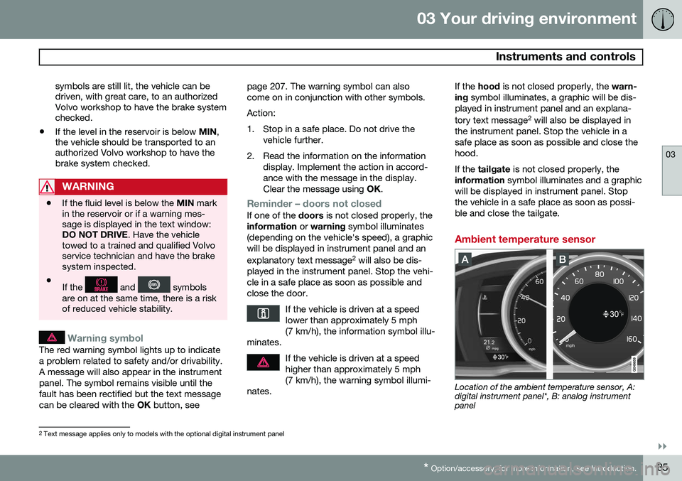
Warning symbol
The red warning symbol lights up to indicate a problem related to safety and/or drivability.A message will also appear in the instrumentpanel. The symbol remains visible until thefault has been rectified but the text messagecan be cleared with the OK button, see page 207. The warning symbol can alsocome on in conjunction with other symbols. Action:
1. Stop in a safe place. Do not drive the
vehicle further.
2. Read the information on the information display. Implement the action in accord- ance with the message in the display.Clear the message using OK.
Reminder – doors not closedIf one of the doors is not closed properly, the
information or warning symbol illuminates
(depending on the vehicle's speed), a graphic will be displayed in instrument panel and an explanatory text message 2
will also be dis-
played in the instrument panel. Stop the vehi- cle in a safe place as soon as possible andclose the door.
If the vehicle is driven at a speedlower than approximately 5 mph(7 km/h), the information symbol illu-
minates.
If the vehicle is driven at a speed higher than approximately 5 mph(7 km/h), the warning symbol illumi-
nates.
If the hood is not closed properly, the warn-
ing symbol illuminates, a graphic will be dis-
played in instrument panel and an explana- tory text message 2
will also be displayed in
the instrument panel. Stop the vehicle in a safe place as soon as possible and close thehood. If the tailgate is not closed properly, the
information symbol illuminates and a graphic
will be displayed in instrument panel. Stop the vehicle in a safe place as soon as possi-ble and close the tailgate.
Ambient temperature sensor
Location of the ambient temperature sensor, A: digital instrument panel*, B: analog instrumentpanel
2 Text message applies only to models with the optional digital instrument panel
Page 88 of 408

03 Your driving environment
Instruments and controls
03
86* Option/accessory, for more information, see Introduction.
NOTE
When the ambient temperature is between 23° and 36 °F (–5° and +2 °C), a snowflakesymbol will be displayed next to the tem-perature. This symbol serves as a warningfor possible slippery road surfaces. Pleasenote that this symbol does not indicate a
fault with your vehicle. At low speeds or when the vehicle is not moving, the temperature readings may beslightly higher than the actual ambienttemperature.
Trip odometers
Trip odometer 3
Odometer display
The trip odometers
T1 and T2 are used to
measure short distances. The distance is shown in the display. Turn the thumb wheel on the left steering wheel lever to display the desired trip odome-ter. Press and hold the RESET button on the left
steering wheel lever for at least 1 second to reset the selected trip odometer 4
.
Clock
Clock, digital instrument panel*
Display 5
Setting the clockThe clock can be set in the
MY CAR menu
system. See page 209 for additional informa- tion about these menus.
1. Go to SettingsSystem optionsTime.
2. The hour box will be selected. Press OK
to activate this box.
3. Turn TUNE to set the correct hour and
press OK to confirm the setting and
deactivate this box.
4. Turn TUNE to select the minute box (A)
and press OK to activate this box (B).
3
The trip odometer will be displayed differently in analog and digital instrument panels
4 Models with a digital information panel: press and hold RESET for more than approximately 4 seconds to reset all trip computer information
5 Models with an analog instrument panel: the time will be displayed in the center of the instrument panel
Page 103 of 408
03 Your driving environment
Lighting
03
}}
101
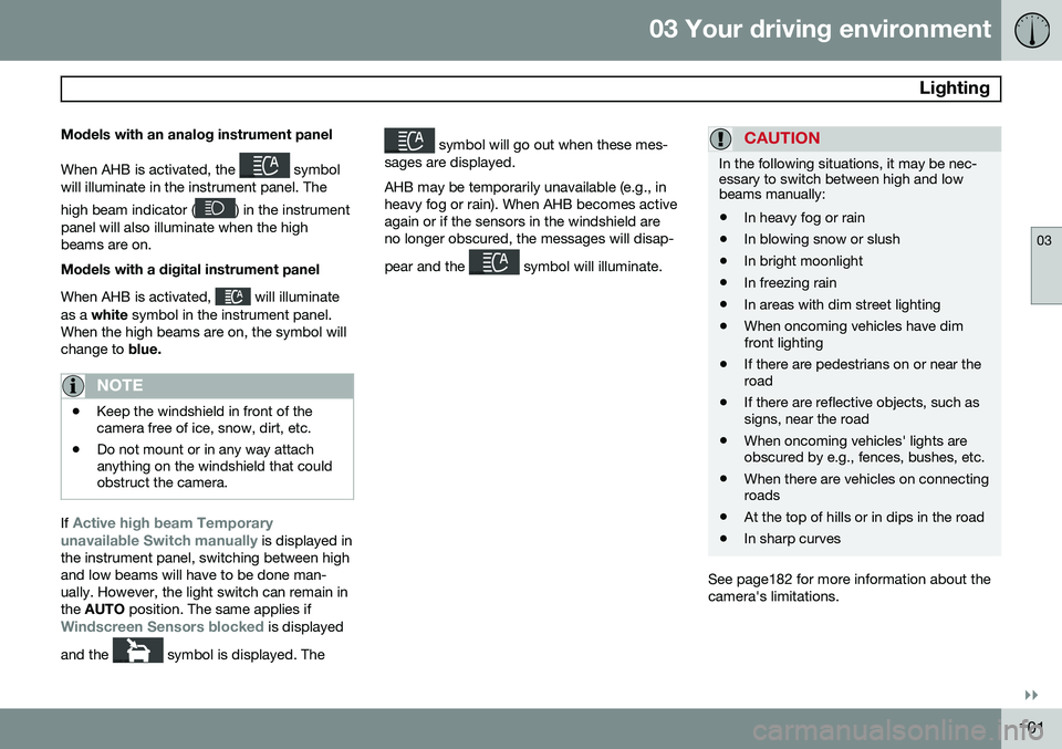
Models with an analog instrument panel When AHB is activated, the
symbol
will illuminate in the instrument panel. The high beam indicator (
) in the instrument
panel will also illuminate when the high beams are on. Models with a digital instrument panel When AHB is activated,
will illuminate
as a white symbol in the instrument panel.
When the high beams are on, the symbol will change to blue.
NOTE
•Keep the windshield in front of the camera free of ice, snow, dirt, etc.
• Do not mount or in any way attachanything on the windshield that couldobstruct the camera.
If Active high beam Temporary
unavailable Switch manually is displayed in
the instrument panel, switching between high and low beams will have to be done man-ually. However, the light switch can remain inthe AUTO position. The same applies if
Windscreen Sensors blocked is displayed
and the
symbol is displayed. The
symbol will go out when these mes-
sages are displayed. AHB may be temporarily unavailable (e.g., in heavy fog or rain). When AHB becomes activeagain or if the sensors in the windshield areno longer obscured, the messages will disap- pear and the
symbol will illuminate.
CAUTION
In the following situations, it may be nec- essary to switch between high and lowbeams manually:
• In heavy fog or rain
• In blowing snow or slush
• In bright moonlight
• In freezing rain
• In areas with dim street lighting
• When oncoming vehicles have dim front lighting
• If there are pedestrians on or near theroad
• If there are reflective objects, such assigns, near the road
• When oncoming vehicles' lights areobscured by e.g., fences, bushes, etc.
• When there are vehicles on connectingroads
• At the top of hills or in dips in the road
• In sharp curves
See page182 for more information about the camera's limitations.
Page 105 of 408
03 Your driving environment
Lighting
03
}}
103
The intensity of the instrument lighting is adjusted with the thumb wheel.
"Theater" lightingWhen the overhead courtesy lighting hasgone out and the engine is running, severalLEDs located near the roof console illuminateto provide faint lighting for the occupants ofthe front seats. This lighting goes out justafter the overhead courtesy lighting when thevehicle is locked.
Parking lights
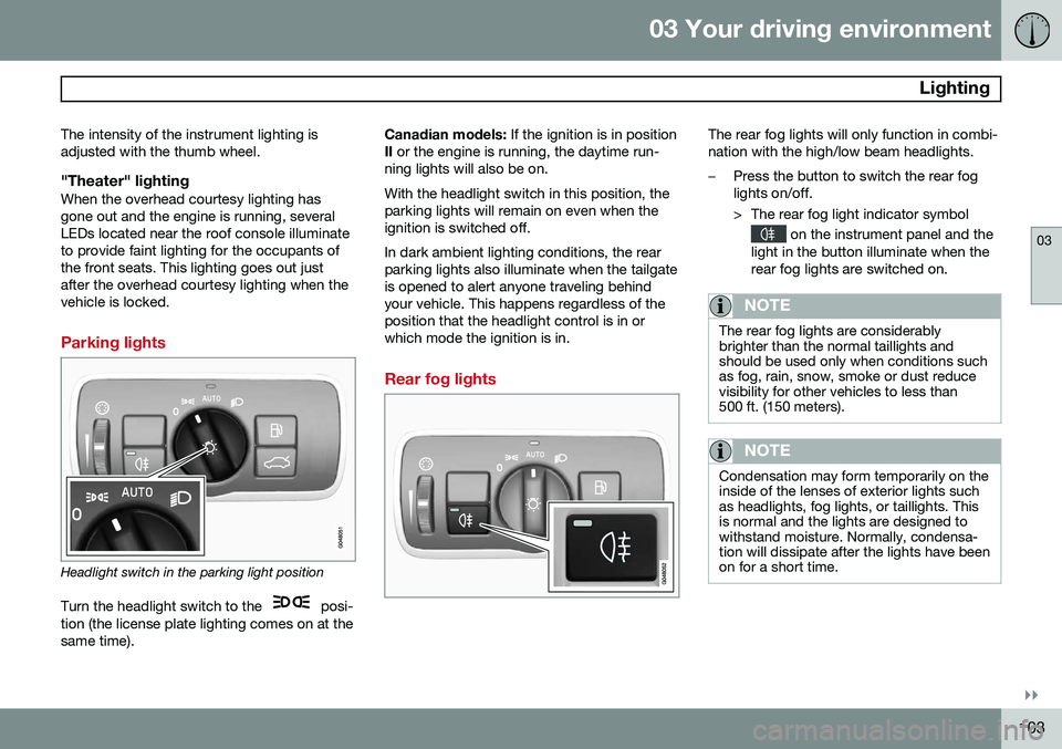
Headlight switch in the parking light position
Turn the headlight switch to the
posi-
tion (the license plate lighting comes on at the same time). Canadian models:
If the ignition is in position
II or the engine is running, the daytime run-
ning lights will also be on. With the headlight switch in this position, the parking lights will remain on even when theignition is switched off. In dark ambient lighting conditions, the rear parking lights also illuminate when the tailgateis opened to alert anyone traveling behindyour vehicle. This happens regardless of theposition that the headlight control is in orwhich mode the ignition is in.
Rear fog lights
The rear fog lights will only function in combi- nation with the high/low beam headlights.
–Press the button to switch the rear fog lights on/off.
> The rear fog light indicator symbol
on the instrument panel and the
light in the button illuminate when the rear fog lights are switched on.
NOTE
The rear fog lights are considerably brighter than the normal taillights andshould be used only when conditions suchas fog, rain, snow, smoke or dust reducevisibility for other vehicles to less than500 ft. (150 meters).
NOTE
Condensation may form temporarily on the inside of the lenses of exterior lights suchas headlights, fog lights, or taillights. Thisis normal and the lights are designed towithstand moisture. Normally, condensa-tion will dissipate after the lights have beenon for a short time.
Page 109 of 408
03 Your driving environment
Wipers and washers
03
}}
* Option/accessory, for more information, see Introduction.107
Windshield wipers/washers
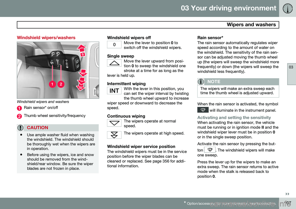
Windshield wipers and washers
Rain sensor* on/off
Thumb wheel sensitivity/frequency
CAUTION
• Use ample washer fluid when washing the windshield. The windshield shouldbe thoroughly wet when the wipers arein operation.
• Before using the wipers, ice and snowshould be removed from the wind-shield/rear window. Be sure the wiperblades are not frozen in place.
Windshield wipers offMove the lever to position
0 to
switch off the windshield wipers.
Single sweepMove the lever upward from posi- tion 0 to sweep the windshield one
stroke at a time for as long as the
lever is held up.
Intermittent wipingWith the lever in this position, you can set the wiper interval by twistingthe thumb wheel upward to increase
wiper speed or downward to decrease thespeed.
Continuous wipingThe wipers operate at normal speed.
The wipers operate at high speed.
Windshield wiper service positionThe windshield wipers must be in the service position before the wiper blades can becleaned or replaced. See page 356 for addi-tional information.
Rain sensor*The rain sensor automatically regulates wiperspeed according to the amount of water onthe windshield. The sensitivity of the rain sen-sor can be adjusted moving the thumb wheelup (the wipers will sweep the windshield morefrequently) or down (the wipers will sweep thewindshield less frequently).
NOTE
The wipers will make an extra sweep each time the thumb wheel is adjusted upward.
When the rain sensor is activated, the symbol
will illuminate in the instrument panel.
Activating and setting the sensitivityWhen activating the rain sensor, the vehicle must be running or in ignition mode II and the
windshield wiper lever must be in position 0
or in the single sweep position. Activate the rain sensor by pressing the but- ton
. The windshield wipers will make
one sweep. Press the lever up for the wipers to make an extra sweep. The rain sensor returns to activemode when the stalk is released back toposition 0.