instrument panel VOLVO XC70 2015 Owner´s Manual
[x] Cancel search | Manufacturer: VOLVO, Model Year: 2015, Model line: XC70, Model: VOLVO XC70 2015Pages: 408, PDF Size: 11.26 MB
Page 230 of 408
05 Comfort and driving pleasure
Trip computer
05
228* Option/accessory, for more information, see Introduction.
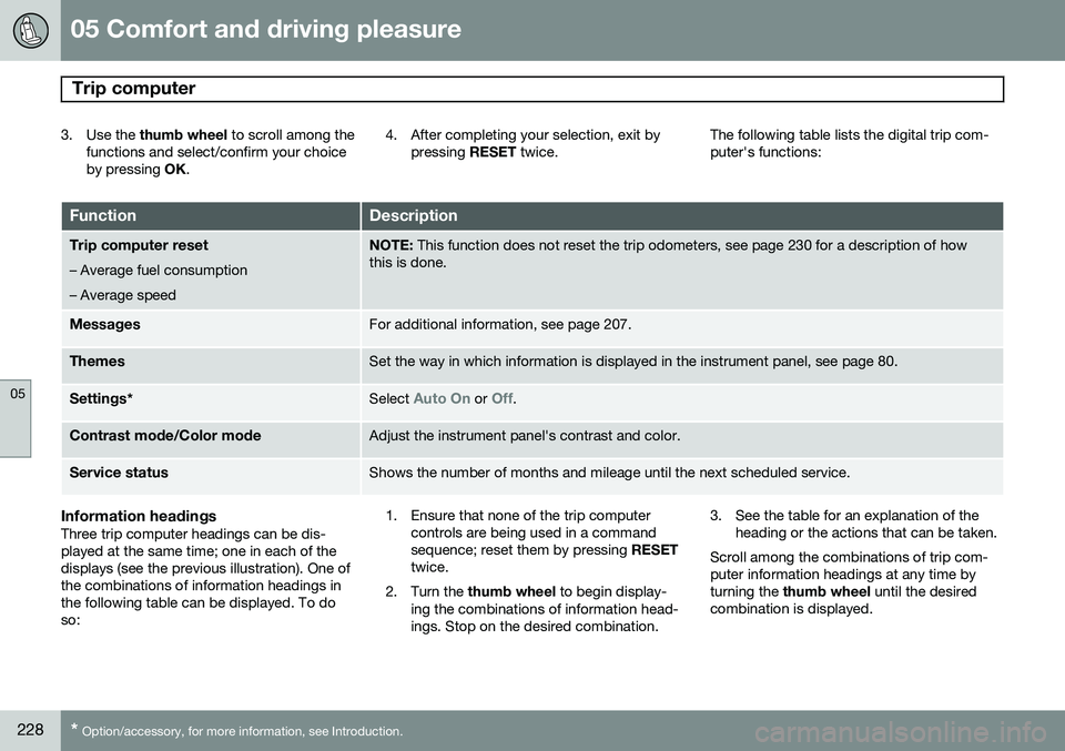
3. Use the thumb wheel to scroll among the
functions and select/confirm your choice by pressing OK. 4. After completing your selection, exit by
pressing RESET twice. The following table lists the digital trip com-puter's functions:
FunctionDescription
Trip computer reset
– Average fuel consumption – Average speedNOTE: This function does not reset the trip odometers, see page 230 for a description of how
this is done.
MessagesFor additional information, see page 207.
ThemesSet the way in which information is displayed in the instrument panel, see page 80.
Settings *Select Auto On or Off.
Contrast mode /Color modeAdjust the instrument panel's contrast and color.
Service statusShows the number of months and mileage until the next scheduled service.
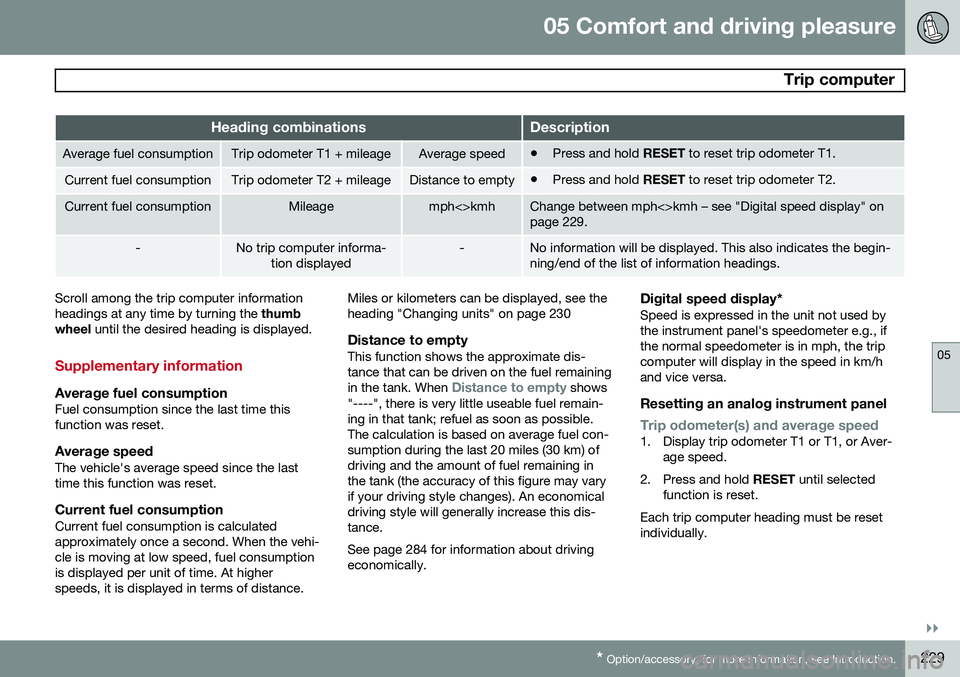
Information headingsThree trip computer headings can be dis- played at the same time; one in each of thedisplays (see the previous illustration). One ofthe combinations of information headings inthe following table can be displayed. To doso: 1. Ensure that none of the trip computer
controls are being used in a commandsequence; reset them by pressing RESET
twice.
2. Turn the thumb wheel to begin display-
ing the combinations of information head-ings. Stop on the desired combination. 3. See the table for an explanation of the
heading or the actions that can be taken.
Scroll among the combinations of trip com-puter information headings at any time byturning the thumb wheel until the desired
combination is displayed.
Page 231 of 408
05 Comfort and driving pleasure
Trip computer
05
}}
* Option/accessory, for more information, see Introduction.229
Heading combinationsDescription
Average fuel consumptionTrip odometer T1 + mileageAverage speed• Press and hold
RESET to reset trip odometer T1.
Current fuel consumptionTrip odometer T2 + mileageDistance to empty•Press and hold
RESET to reset trip odometer T2.
Current fuel consumptionMileagemph<>kmhChange between mph<>kmh – see "Digital speed display" on page 229.
-No trip computer informa-
tion displayed-No information will be displayed. This also indicates the begin- ning/end of the list of information headings.
Scroll among the trip computer information headings at any time by turning the thumb
wheel until the desired heading is displayed.
Supplementary information
Average fuel consumptionFuel consumption since the last time this function was reset.
Average speedThe vehicle's average speed since the lasttime this function was reset.
Current fuel consumptionCurrent fuel consumption is calculatedapproximately once a second. When the vehi-cle is moving at low speed, fuel consumptionis displayed per unit of time. At higherspeeds, it is displayed in terms of distance. Miles or kilometers can be displayed, see theheading "Changing units" on page 230
Distance to emptyThis function shows the approximate dis-tance that can be driven on the fuel remaining in the tank. When
Distance to empty shows
"----", there is very little useable fuel remain- ing in that tank; refuel as soon as possible.The calculation is based on average fuel con-sumption during the last 20 miles (30 km) ofdriving and the amount of fuel remaining inthe tank (the accuracy of this figure may varyif your driving style changes). An economicaldriving style will generally increase this dis-tance. See page 284 for information about driving economically.
Digital speed display*Speed is expressed in the unit not used bythe instrument panel's speedometer e.g., ifthe normal speedometer is in mph, the tripcomputer will display in the speed in km/hand vice versa.
Resetting an analog instrument panel
Trip odometer(s) and average speed1. Display trip odometer T1 or T1, or Aver- age speed.
2. Press and hold RESET until selected
function is reset.
Each trip computer heading must be reset individually.
Page 232 of 408
05 Comfort and driving pleasure
Trip computer
05
230* Option/accessory, for more information, see Introduction.
Resetting a digital instrument panel
Trip odometer1. Turn the thumb wheel to select the com-
bination of headings containing the trip odometer to be reset.
2. Press and hold RESET until selected trip
odometer is reset.
Average speed and fuel consumption1. Select Trip computer reset and press
OK .
2. Select one of the following alternatives using the thumb wheel and press OK:
• mpg
• mph
• Reset both
3. Finish by pressing RESET.
Changing unitsTo change the unit (miles/km) used to meas- ure distance and speed, go to
MY CAR
SettingsSystem optionsDistance
and fuel units.
NOTE
In addition to changing units in the trip computer, this also changes the units usedin the Volvo Navigation System (VNS)*.
Trip statistics*
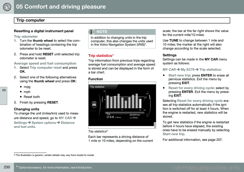
Trip information from previous trips regarding average fuel consumption and average speedis stored and can be displayed in the form ofa bar chart.
Function
Trip statistics 2
Each bar represents a driving distance of 1 mile or 10 miles, depending on the current scale; the bar at the far right shows the valuefor the current mile/10 miles. Use
TUNE to change between 1 mile and
10 miles; the marker at the right will also change according to the scale selected.
SettingsSettings can be made in the MY CAR menu
system as follows:
MY CARMy XC70Trip statistics:
•
Start new trip: press ENTER to erase all
pervious statistics. Exit the menu by pressing EXIT.
•
Reset for every driving cycle: select by
pressing ENTER. Exit the menu by press-
ing EXIT .
Selecting
Reset for every driving cycle era-
ses all trip statistics automatically if the igni- tion is switched off for at least 4 hours. Whenthe engine is restarted, new statistics will bestored. To get new statistics if the engine is restarted before 4 hours have elapsed, the existingones have to be erased manually by selecting
Start new trip.
For additional information, see page 207.
2 The illustration is generic; certain details may vary from model to model
Page 234 of 408
05 Comfort and driving pleasure
Active chassis system–Four C*
05
232* Option/accessory, for more information, see Introduction.
Active chassis (Four C)
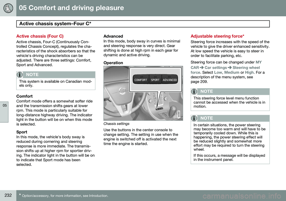
Active chassis, Four-C (Continuously Con- trolled Chassis Concept), regulates the cha-racteristics of the shock absorbers so that thevehicle's driving characteristics can beadjusted. There are three settings: Comfort,Sport and Advanced.
NOTE
This system is available on Canadian mod- els only.
ComfortComfort mode offers a somewhat softer ride and the transmission shifts gears at lowerrpm. This mode is particularly suitable forlong-distance highway driving. The indicatorlight in the button will be on when this modeis selected.
SportIn this mode, the vehicle's body sway isreduced during cornering and steeringresponse is more immediate. The transmis-sion shifts up at higher rpm for sportier driv-ing. The indicator light in the button will be onto indicate that Sport mode has beenselected.
AdvancedIn this mode, body sway in curves is minimaland steering response is very direct. Gearshifting is done at high rpm in each gear fordynamic and active driving.
Operation
Chassis settings
Use the buttons in the center console to change setting. The setting in use when theengine is switched off is activated the nexttime the engine is started.
Adjustable steering force*
Steering force increases with the speed of the vehicle to give the driver enhanced sensitivity.At low speed the vehicle is easy to steer inorder to facilitate parking, etc. Steering force can be changed under
MY
CAR
Car settingsSteering wheel
force
. Select Low, Medium or High. For a
description of the menu system, see page 209.
NOTE
This steering force level menu function cannot be accessed when the vehicle is inmotion.
NOTE
In certain situations, the power steering may become too warm and will have to betemporarily cooled down. While this ishappening, the power steering effect willbe reduced slightly and somewhat moreeffort may be required to turn the steeringwheel. If this occurs, a message will be displayed in the instrument panel.
Page 290 of 408
07 During your trip
Refueling
07
288
Fuel requirements
Deposit control gasoline (detergentadditives)
Volvo recommends the use of detergent gas- oline to control engine deposits. Detergentgasoline is effective in keeping injectors andintake valves clean. Consistent use of depositcontrol gasolines will help ensure good driva-bility and fuel economy. If you are not surewhether the gasoline contains deposit controladditives, check with the service station oper-ator.
NOTE
Volvo does not recommend the use of external fuel injector cleaning systems.
Unleaded fuelEach Volvo has a three-way catalytic con- verter and must use only unleaded gasoline.U.S. and Canadian regulations require thatpumps delivering unleaded gasoline belabeled "UNLEADED". Only these pumpshave nozzles which fit your vehicle's fillerinlet. It is unlawful to dispense leaded fuelinto a vehicle labeled "unleaded gasolineonly". Leaded gasoline damages the three-way catalytic converter and the heated oxy-gen sensor system. Repeated use of leaded gasoline will lessen the effectiveness of theemission control system and could result inloss of emission warranty coverage. Stateand local vehicle inspection programs willmake detection of misfueling easier, possiblyresulting in emission test failure for misfueledvehicles.
NOTE
Some U.S. and Canadian gasolines con- tain an octane enhancing additive calledmethyl-cyclopentadienyl manganese tri-carbonyl (MMT). If such fuels are used,your Emission Control System perform-ance may be affected, and the CheckEngine Light (malfunction indicator light)located on your instrument panel maylight. If this occurs, please return yourvehicle to a trained and qualified Volvoservice technician for service.
Gasoline containing alcohol and ethers, "Oxygenated fuels"
Some fuel suppliers sell gasoline containing "oxygenates" which are usually alcohols orethers. In some areas, state or local lawsrequire that the service pump be marked indi- cating use of alcohols or ethers. However,there are areas in which the pumps areunmarked. If you are not sure whether there isalcohol or ethers in the gasoline you buy,check with the service station operator. Tomeet seasonal air quality standards, someareas require the use of "oxygenated" fuel. Volvo allows the use of the following "oxy- genated" fuels; however, the octane ratingslisted on page 289 must still be met.
Alcohol – EthanolFuels containing up to 10% ethanol by vol- ume may be used. Ethanol may also be refer-red to as Ethyl alcohol, or "Gasohol". Ethers – MTBE: Fuels containing up to 15% MTBE may be used.
MethanolDo not use gasolines containing methanol(methyl alcohol, wood alcohol). This practicecan result in vehicle performance deteriora-tion and can damage critical parts in the fuelsystem. Such damage may not be coveredunder the New Vehicle Limited Warranty.
Page 336 of 408
08 Wheels and tires
Tire Pressure Monitoring System (TPMS)
08
334
Introduction
NOTE
USA – FCC ID: KR5S122780002 This device complies with part 15 of the FCC rules. Operation is subject to the fol-lowing conditions: (1) This device may notcause harmful interference, and (2) thisdevice must accept any interferencereceived, including interference that maycause undesired operation.
The tire pressure monitoring system1
uses
sensors mounted in the tire valves to check inflation pressure levels. When the vehicle ismoving at a speed of approximately 20 mph(30 km/h) or faster, these sensors transmitinflation pressure data to a receiver located inthe vehicle. When low inflation pressure is detected or if a sensor is not functioning properly, TPMS will light up the tire pressure warning light (
)
(also referred to as a telltale) in the instrument panel and will display one of the following messages in the text window:
Tire pressure
low or
Tire needs air now.
NOTE
If a fault occurs in TPMS, the tire pressure warning light will flash for approximately 1 minute and
Tire press. syst Service
required will be displayed.
Each tire, including the spare (if provided), should be checked monthly when cold andinflated to the inflation pressure recom-mended by the vehicle manufacturer on thevehicle placard or tire inflation pressure label.(If your vehicle has tires of a different sizethan the size indicated on the vehicle placardor tire inflation pressure label, you shoulddetermine the proper tire inflation pressure forthose tires.) As an added safety feature, your vehicle has been equipped with a tire pressure monitor-ing system (TPMS) that illuminates a low tirepressure telltale when one or more of yourtires is significantly under-inflated. Accord-ingly, when the low tire pressure telltale illu-minates, you should stop and check yourtires as soon as possible, and inflate them tothe proper pressure. Driving on a significantlyunder-inflated tire causes the tire to overheatand can lead to tire failure. Under-inflationalso reduces fuel efficiency and tire tread life, and may affect the vehicle's handling andstopping ability. Please note that the TPMS is not a substitute for proper tire maintenance, and it is the driv-er's responsibility to maintain correct tirepressure, even if under-inflation has notreached the level to trigger illumination of theTPMS low tire pressure telltale. Your vehicle has also been equipped with a TPMS malfunction indicator to indicate whenthe system is not operating properly. TheTPMS malfunction indicator is combined withthe low tire pressure telltale. When the sys-tem detects a malfunction, the telltale willflash for approximately one minute and thenremain continuously illuminated. Thissequence will continue upon subsequentvehicle start-ups as long as the malfunctionexists. When the malfunction indicator is illu-minated, the system may not be able todetect or signal low tire pressure as intended.TPMS malfunctions may occur for a variety ofreasons, including the installation of replace-ment or alternate tires or wheels on the vehi-cle that prevent the TPMS from functioningproperly. Always check the TPMS malfunc-tion telltale after replacing one or more tiresor wheels on your vehicle to ensure that thereplacement or alternate tires and wheels
1
Not available in all markets or in all models.
Page 371 of 408
09 Maintenance and specifications
Fuses09
}}
* Option/accessory, for more information, see Introduction.369
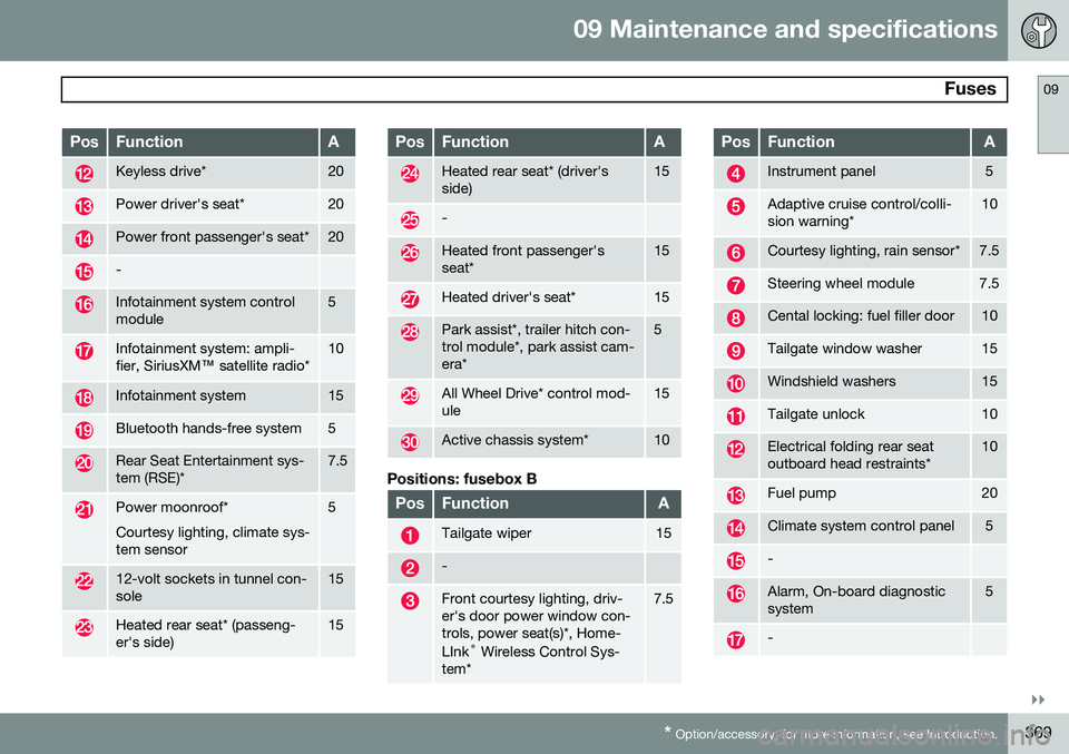
PosFunctionA
Keyless drive*20
Power driver's seat*20
Power front passenger's seat*20
-
Infotainment system control module5
Infotainment system: ampli- fier, SiriusXM ™ satellite radio*10
Infotainment system15
Bluetooth hands-free system5
Rear Seat Entertainment sys- tem (RSE)*7.5
Power moonroof* Courtesy lighting, climate sys- tem sensor5
12-volt sockets in tunnel con- sole15
Heated rear seat* (passeng- er's side)15
PosFunctionA
Heated rear seat* (driver's side)15
-
Heated front passenger's seat*15
Heated driver's seat*15
Park assist*, trailer hitch con- trol module*, park assist cam-era*5
All Wheel Drive* control mod- ule15
Active chassis system*10
Positions: fusebox B
PosFunctionA
Tailgate wiper15
-
Front courtesy lighting, driv- er's door power window con-trols, power seat(s)*, Home- LInk ®
Wireless Control Sys-
tem*7.5
PosFunctionA
Instrument panel5
Adaptive cruise control/colli- sion warning*10
Courtesy lighting, rain sensor*7.5
Steering wheel module7.5
Cental locking: fuel filler door10
Tailgate window washer15
Windshield washers15
Tailgate unlock10
Electrical folding rear seat outboard head restraints*10
Fuel pump20
Climate system control panel5
-
Alarm, On-board diagnostic system5
-
Page 393 of 408
10 Specifications
Overview of information and warning symbols
10
}}
* Option/accessory, for more information, see Introduction.391
Introduction
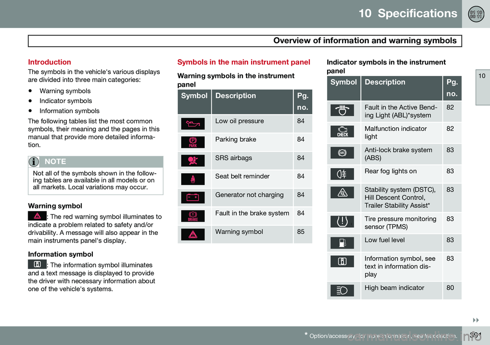
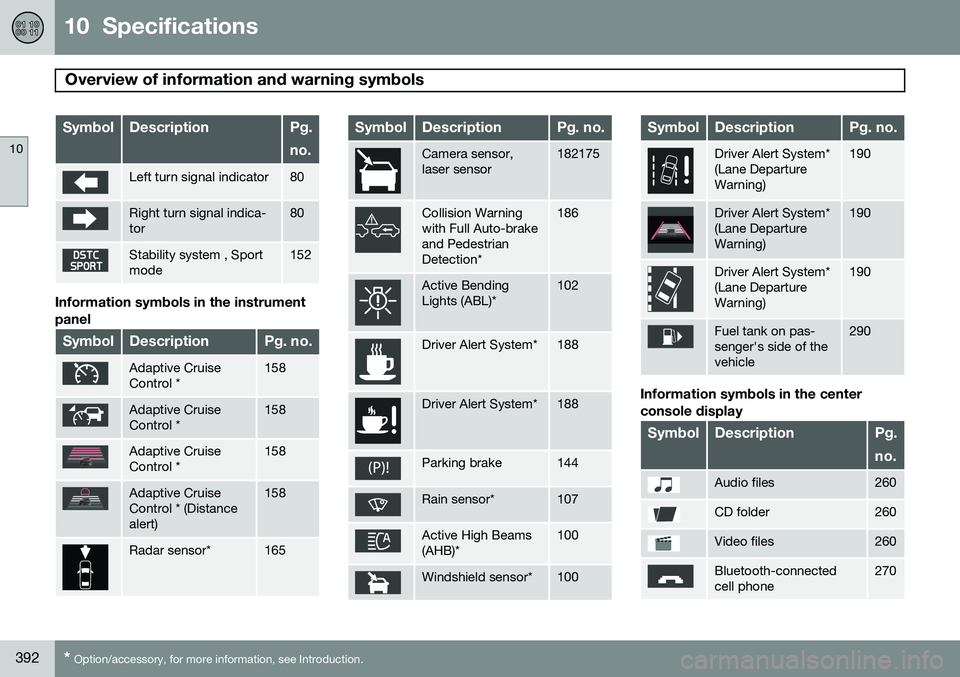
The symbols in the vehicle's various displays are divided into three main categories:
• Warning symbols
• Indicator symbols
• Information symbols
The following tables list the most commonsymbols, their meaning and the pages in thismanual that provide more detailed informa-tion.
NOTE
Not all of the symbols shown in the follow- ing tables are available in all models or onall markets. Local variations may occur.
Warning symbol
: The red warning symbol illuminates to
indicate a problem related to safety and/or drivability. A message will also appear in themain instruments panel's display.
Information symbol
: The information symbol illuminates
and a text message is displayed to provide the driver with necessary information aboutone of the vehicle's systems.
Symbols in the main instrument panel
Warning symbols in the instrument
panel
SymbolDescriptionPg. no.
Low oil pressure84
Parking brake84
SRS airbags84
Seat belt reminder84
Generator not charging84
Fault in the brake system84
Warning symbol85
Indicator symbols in the instrument panel
SymbolDescriptionPg. no.
Fault in the Active Bend- ing Light (ABL)*system82
Malfunction indicator light82
Anti-lock brake system (ABS)83
Rear fog lights on83
Stability system (DSTC), Hill Descent Control,Trailer Stability Assist*83
Tire pressure monitoring sensor (TPMS)83
Low fuel level83
Information symbol, see text in information dis-play83
High beam indicator80
Page 394 of 408
10 Specifications
Overview of information and warning symbols
10
392* Option/accessory, for more information, see Introduction.
SymbolDescriptionPg. no.
Left turn signal indicator80
Right turn signal indica- tor80
Stability system , Sport mode152
Information symbols in the instrument panel
SymbolDescriptionPg. no.
Adaptive Cruise Control *158
Adaptive Cruise Control *158
Adaptive Cruise Control *158
Adaptive Cruise Control * (Distancealert)158
Radar sensor*165
SymbolDescriptionPg. no.
Camera sensor, laser sensor182175
Collision Warning with Full Auto-brakeand PedestrianDetection*186
Active Bending Lights (ABL)*102
Driver Alert System*188
Driver Alert System*188
Parking brake144
Rain sensor*107
Active High Beams (AHB)*100
Windshield sensor*100
SymbolDescriptionPg. no.
Driver Alert System* (Lane DepartureWarning)190
Driver Alert System* (Lane DepartureWarning)190
Driver Alert System* (Lane DepartureWarning)190
Fuel tank on pas- senger's side of thevehicle290
Information symbols in the center console display
SymbolDescriptionPg. no.
Audio files260
CD folder260
Video files260
Bluetooth-connected cell phone270
Page 402 of 408
11 Index
11
400
Inspection readiness................................ 342
Instrument lighting................................... 102"theater" lighting................................. 102
Instrument overview............................ 78, 79
Instrument panel................................ 79, 207
Integrated two-stage booster cushion...... 51
Interior Air Quality System....................... 216
Interior lighting................................. 104, 105iPod ® connector (audio system)............. 264
ISOFIX/LATCH anchors............................. 48
J
Jack attaching............................................. 331
location of........................................... 331
Jump starting........................................... 125
K
Key blade................................. 58, 64, 67, 68 private locking...................................... 67
Keyless drive general description............................... 68
starting the vehicle............................. 122
L
Labels list of................................................... 383
location of........................................... 382
Lane Departure Warning (LDW)............... 190
LATCH anchors......................................... 48
Leather care............................................. 376
Lighting panel............................................ 99
Load anchoring eyelets........................... 295Loading floor rails............................................. 295
hooks for securing loads............ 295, 296
Loading the vehicle.......................... 293, 320 roof loads............................................ 297
Locking...................................................... 71 tailgate.................................................. 72 Locking the vehicle.................................... 61
Locks, child safety..................................... 54
Low beams.............................................. 100
Low oil pressure warning light................... 83
M
Main instrument panel............................. 207
Maintenance............................................ 340
hoisting the vehicle............................. 342
performed by the owner..................... 341
Malfunction indicator light......................... 82
Media player (infotainment system)......... 259
Menu........................................................ 209
Messages in the instrument panel........... 207Mirrors defroster............................................. 113
power door......................................... 112
rearview, auto-dim function................ 113
retractable........................................... 112
vanity.................................................. 235
Moonroof................................................. 117