open VOLVO XC90 2014 Owner´s Manual
[x] Cancel search | Manufacturer: VOLVO, Model Year: 2014, Model line: XC90, Model: VOLVO XC90 2014Pages: 308, PDF Size: 13.31 MB
Page 154 of 308
06 Starting and driving
Jump starting
06
152
G030860
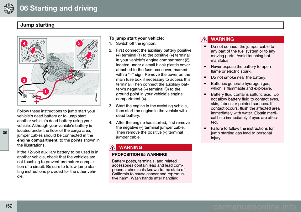
Follow these instructions to jump start your vehicle's dead battery or to jump startanother vehicle's dead battery using yourvehicle. Although your vehicle's battery islocated under the floor of the cargo area,jumper cables should be connected in theengine compartment, to the points shown in
the illustrations. If the 12-volt auxiliary battery to be used is in another vehicle, check that the vehicles arenot touching to prevent premature comple-tion of a circuit. Be sure to follow jump star-ting instructions provided for the other vehi-cle.
To jump start your vehicle:1. Switch off the ignition.
2. First connect the auxiliary battery positive (+) terminal (1) to the positive (+) terminal in your vehicle's engine compartment (2),located under a small black plastic coverattached to the fuse box cover, markedwith a "+" sign. Remove the cover on themain fuse box if necessary to access thisterminal. Then connect the auxiliary bat-tery's negative (–) terminal (3) to theground point in your vehicle's enginecompartment (4).
3. Start the engine in the assisting vehicle, then start the engine in the vehicle withdead battery.
4. After the engine has started, first remove the negative (–) terminal jumper cable.Then remove the positive (+) terminaljumper cable.
WARNING
PROPOSITION 65 WARNING! Battery posts, terminals, and related accessories contain lead and lead com-pounds, chemicals known to the state ofCalifornia to cause cancer and reproduc-tive harm. Wash hands after handling.
WARNING
•Do not connect the jumper cable to any part of the fuel system or to anymoving parts. Avoid touching hotmanifolds.
• Never expose the battery to openflame or electric spark.
• Do not smoke near the battery.
• Batteries generate hydrogen gas,which is flammable and explosive.
• Battery fluid contains sulfuric acid. Donot allow battery fluid to contact eyes,skin, fabrics or painted surfaces. Ifcontact occurs, flush the affected areaimmediately with water. Obtain medi-cal help immediately if eyes are affec-ted.
• Failure to follow the instructions forjump starting can lead to personalinjury.
Page 155 of 308
06 Starting and driving
All Wheel Drive*
06
* Option/accessory, for more information, see Introduction.153
All Wheel Drive (AWD) – general information
Your Volvo can be equipped with an electron- ically controlled All Wheel Drive system*,which means that power is distributed auto-matically between the front and rear wheels.Under normal driving conditions, most of theengine's power is directed to the frontwheels. However, if there is any tendency forthe front wheels to spin, an electronicallycontrolled coupling distributes power to thewheels that have the best traction.
Tire dimensionsVolvo recommends that you always drive ontires of the same brand, size, construction(radial), tread pattern, load-, speed-, traction-,temperature-, and treadwear rating. Neverdrive on mixed tires, except for brief periodswhen the temporary spare tire is in use. Always use properly inflated tires of correct dimensions. Tire size and inflation pressuresare shown on the tire inflation pressure plac-ards, located on the driver's side B-pillar (thestructural member at the side of the vehicle,at the rear of the driver's door opening), or onthe inside of the fuel filler door on Canadianmodels.
Temporary SpareThe temporary spare tire is for temporary,low-speed, short-distance use only. Replaceit with a full-sized tire as soon as possible. Donot drive on the temporary spare at speedsabove 50 m.p.h. (80 km/h).
NOTE
Never install snow chains on a temporary spare.
Page 164 of 308
06 Starting and driving
Towing
06
162
G027042
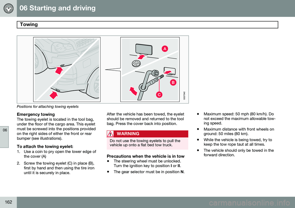
Positions for attaching towing eyelets
Emergency towingThe towing eyelet is located in the tool bag, under the floor of the cargo area. This eyeletmust be screwed into the positions providedon the right sides of either the front or rearbumper (see illustrations).
To attach the towing eyelet:1. Use a coin to pry open the lower edge ofthe cover (A)
2. Screw the towing eyelet (C) in place (B), first by hand and then using the tire ironuntil it is securely in place. After the vehicle has been towed, the eyeletshould be removed and returned to the toolbag. Press the cover back into position.
WARNING
Do not use the towing eyelets to pull the vehicle up onto a flat bed tow truck.
Precautions when the vehicle is in tow
•
The steering wheel must be unlocked. Turn the ignition key to position
I or II.
• The gear selector must be in position
N. •
Maximum speed: 50 mph (80 km/h). Donot exceed the maximum allowable tow-ing speed.
• Maximum distance with front wheels onground: 50 miles (80 km).
• While the vehicle is being towed, try tokeep the tow rope taut at all times.
• The vehicle should only be towed in theforward direction.
Page 180 of 308
07 Wheels and tires
General information
07
178
Introduction
Your vehicle is equipped with tires according to the vehicle's tire information placard on theB-pillar (the structural member at the side ofthe vehicle, at the rear of the driver's dooropening).
CAUTION
Some Volvo models are equipped with an Ultra High Performance tire and wheelcombination designed to provide maxi-mum dry pavement performance with con-sideration for hydroplaning resistance.They may be more susceptible to roadhazard damage and, depending on drivingconditions, may achieve a tread life of lessthan 20,000 miles (30,000 km). Even if thisvehicle is equipped with Volvo’s advancedAWD or DSTC system, these tires are notdesigned for winter driving, and should bereplaced with winter tires when weatherconditions dictate.
The tires have good road holding characteris- tics and offer good handling on dry and wetsurfaces. It should be noted however that thetires have been developed to give these fea-tures on snow/ice-free surfaces. Most models are equipped with "all-season" tires, which provide a somewhat higherdegree of road holding on slippery surfacesthan tires without the "all-season" rating.However, for optimum road holding on icy orsnow-covered roads, we recommend suitablewinter tires on all four wheels. When replacing tires, be sure that the new tires are the same size designation, type(radial) and preferably from the same manu-facturer, on all four wheels. Otherwise there isa risk of altering the car's roadholding andhandling characteristics.
New Tires
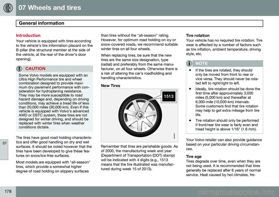
Remember that tires are perishable goods. Asof 2000, the manufacturing week and year(Department of Transportation (DOT) stamp)will be indicated with 4 digits (e.g., 1513means that the tire illustrated was manufac-tured during week 15 of 2013).
Tire rotationYour vehicle has no required tire rotation. Tire wear is affected by a number of factors suchas tire inflation, ambient temperature, drivingstyle, etc.
NOTE
•
If the tires are rotated, they should only be moved from front to rear orvice versa. They should never be rota-ted left to right/right to left.
• Ideally, tire rotation should be done thefirst time after approximately 3,000miles (5,000 km) and thereafter at6,000-mile (10,000-km) intervals.Some customers find that tire rotationmay help to get extra mileage from tirelife.
• Tire rotation should only be performedif front/rear tire wear is fairly even andtread height is above 1/16" (1.6 mm).
Your Volvo retailer can also provide guidance based on your particular driving circumstan-ces.
Tire ageTires degrade over time, even when they arenot being used. It is recommended that tiresgenerally be replaced after 6 years of normalservice. Heat caused by hot climates, fre-
Page 183 of 308
07 Wheels and tires
Tire inflation
07
181
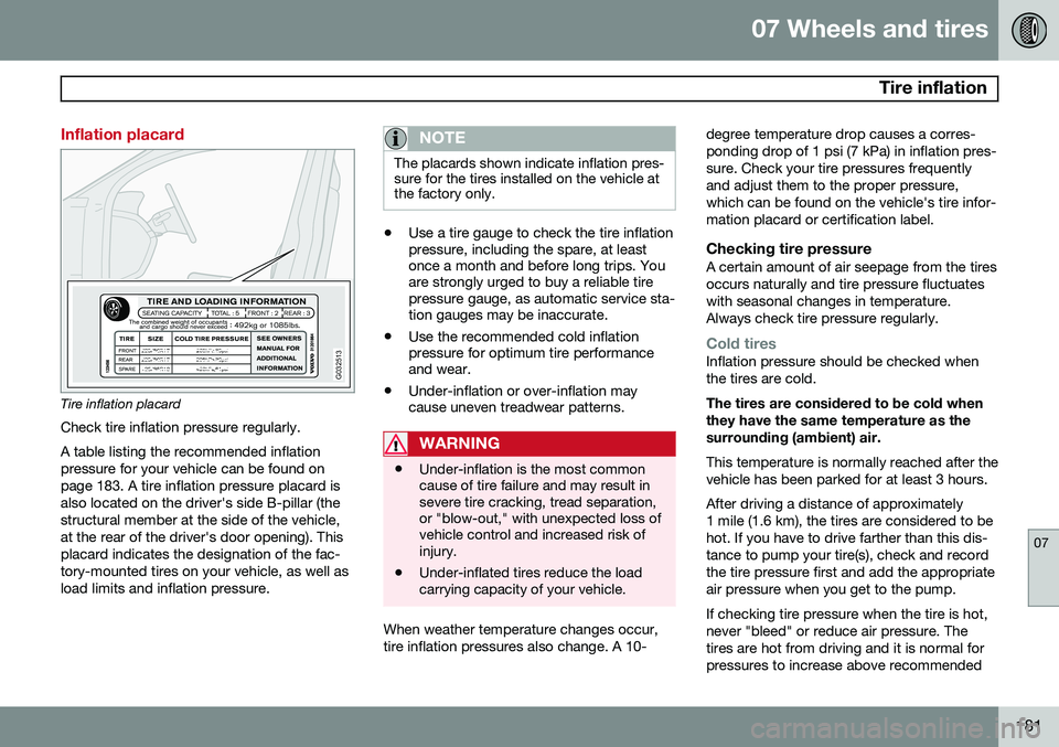
Inflation placard
G032513
Tire inflation placardCheck tire inflation pressure regularly. A table listing the recommended inflation pressure for your vehicle can be found onpage 183. A tire inflation pressure placard isalso located on the driver's side B-pillar (thestructural member at the side of the vehicle,at the rear of the driver's door opening). Thisplacard indicates the designation of the fac-tory-mounted tires on your vehicle, as well asload limits and inflation pressure.
NOTE
The placards shown indicate inflation pres- sure for the tires installed on the vehicle atthe factory only.
• Use a tire gauge to check the tire inflation pressure, including the spare, at leastonce a month and before long trips. Youare strongly urged to buy a reliable tirepressure gauge, as automatic service sta-tion gauges may be inaccurate.
• Use the recommended cold inflationpressure for optimum tire performanceand wear.
• Under-inflation or over-inflation maycause uneven treadwear patterns.
WARNING
•Under-inflation is the most common cause of tire failure and may result insevere tire cracking, tread separation,or "blow-out," with unexpected loss ofvehicle control and increased risk ofinjury.
• Under-inflated tires reduce the loadcarrying capacity of your vehicle.
When weather temperature changes occur, tire inflation pressures also change. A 10- degree temperature drop causes a corres-ponding drop of 1 psi (7 kPa) in inflation pres-sure. Check your tire pressures frequentlyand adjust them to the proper pressure,which can be found on the vehicle's tire infor-mation placard or certification label.
Checking tire pressureA certain amount of air seepage from the tiresoccurs naturally and tire pressure fluctuateswith seasonal changes in temperature.Always check tire pressure regularly.
Cold tiresInflation pressure should be checked when the tires are cold. The tires are considered to be cold when they have the same temperature as thesurrounding (ambient) air. This temperature is normally reached after the vehicle has been parked for at least 3 hours. After driving a distance of approximately 1 mile (1.6 km), the tires are considered to behot. If you have to drive farther than this dis-tance to pump your tire(s), check and recordthe tire pressure first and add the appropriateair pressure when you get to the pump. If checking tire pressure when the tire is hot, never "bleed" or reduce air pressure. Thetires are hot from driving and it is normal forpressures to increase above recommended
Page 194 of 308
07 Wheels and tires
Tire Sealing System
07
192* Option/accessory, for more information, see Introduction.
Introduction
Certain models are equipped with a tire seal- ing system* that enables you to temporarilyseal a hole in the tread surface and re-inflatea flat tire, or to adjust a tire’s inflation pres-sure. The system consists of an air compressor, a container for the sealing compound, wiring toconnect the system to the vehicle’s electricalsystem via one of the 12-volt sockets, and ahose used to connect the system to the tire’sinflation valve.
NOTE
The tire sealing system's compressor has been tested and approved by Volvo.
The 12-volt sockets are located on the rear side of the center console (in the rear seat)and in the cargo area.
Accessing the tire sealing systemThe tire sealing system is stowed under thefloor of the cargo area. To access it:
1. Fold up or remove any protective floor
covering or carpet.
2. Open the floor hatch.
3. Lift out the tire sealing system.
NOTE
• The tire sealing system is only intended to seal holes on the tire’stread area, not the sidewall.
• Tires with large holes or tears cannotbe repaired with the tire sealing sys-tem.
• After use, stow the tire sealing systemproperly to help prevent rattling.
WARNING
•After using the tire sealing system, the vehicle should not be driven fartherthan approximately 120 miles (200km).
• Have the tire inspected by a trainedand qualified Volvo service technicianas soon as possible to determine if itcan be permanently repaired or mustbe replaced.
• The vehicle should not be driven fasterthan 50 mph (80 km/h) while using atire that has been temporarily repairedwith the tire sealing system.
• After using the tire sealing system,drive carefully and avoid abrupt steer-ing maneuvers and sudden stops.
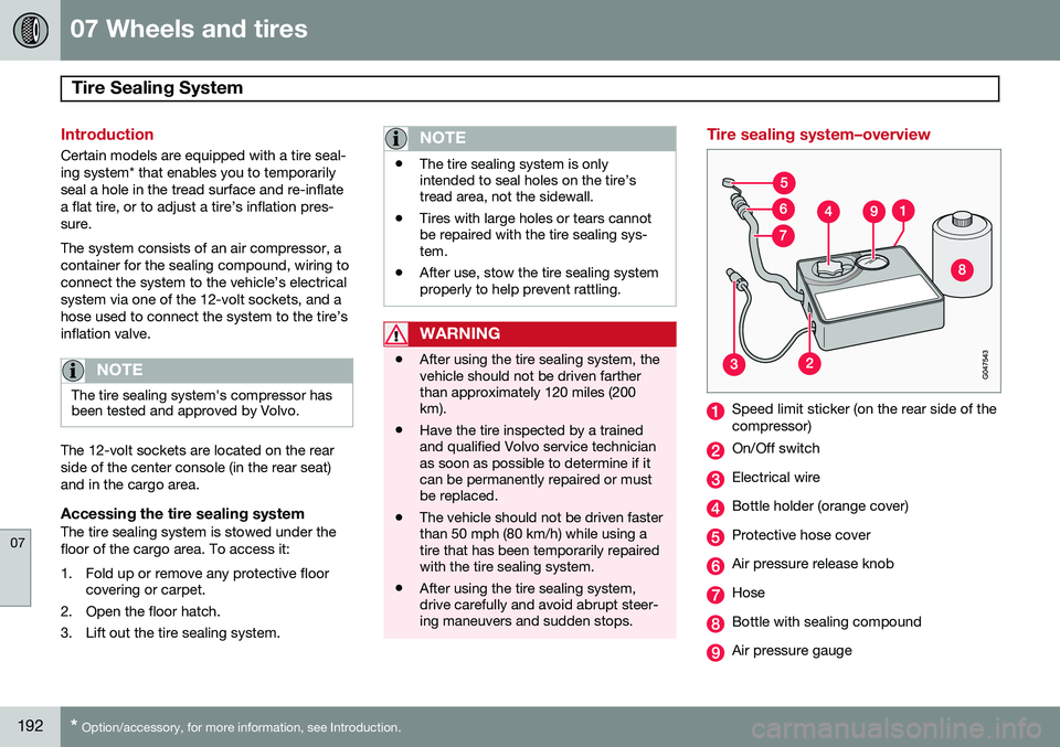
Tire sealing system–overview
Speed limit sticker (on the rear side of the compressor)
On/Off switch
Electrical wire
Bottle holder (orange cover)
Protective hose cover
Air pressure release knob
Hose
Bottle with sealing compound
Air pressure gauge
Page 229 of 308
09 Maintenance and servicing
Battery09
227
Battery maintenance
The battery in your vehicle is located under the floor of the cargo compartment. Driving habits and conditions, climate, the number of starts, etc. all affect the service lifeand function of the battery. In order for yourbattery to perform satisfactorily, keep the fol-lowing in mind:
• Use a screw driver to open the caps or cover and a flashlight to inspect the level.
• If necessary, add distilled water. The levelshould never be above the indicator.
• The fluid level should be checked if thebattery has been recharged.
• After inspection, be sure the cap overeach battery cell or the cover is securelyin place.
• Check that the battery cables are cor-rectly connected and properly tightened.
• Never disconnect the battery when theengine is running, or when the key is inthe ignition. This could damage the vehi-cle's electrical system.
• The battery should be disconnected fromthe vehicle when a battery charger isused directly on the battery.
• To help keep the battery in good condi-tion, the vehicle should be driven for atleast 15 minutes a week or connected to a charger with an automatic chargingfunction.
• If the battery is fully discharged a numberof times, this may shorten its service life.Keeping the battery fully charged helpsprolong its service life.
• The service life of a battery is affected byfactors such as driving conditions and cli-mate. Extreme cold may also furtherdecrease the battery’s starting capacity.
• Because the battery’s starting capacitydecreases with time, it may be necessaryto recharge it if the vehicle is not drivenfor an extended period of time or if thevehicle is usually only driven short dis-tances.
•
WARNING
PROPOSITION 65 WARNING! Battery posts, terminals, and related accessories contain lead and lead com-pounds, chemicals known to the state ofCalifornia to cause cancer and reproduc-tive harm. Wash hands after handling.
WARNING
• Never expose the battery to open flame or electric spark.
• Do not smoke near the battery.
• Battery fluid contains sulfuric acid. Donot allow battery fluid to contact eyes,skin, fabrics or painted surfaces. Ifcontact occurs, flush the affected areaimmediately with water. Obtain medi-cal help immediately if eyes are affec-ted.
NOTE
Used batteries should be properly dis- posed of at a recycling station or similarfacility, or taken to your Volvo retailer.
Page 230 of 308
09 Maintenance and servicing
Battery 09
228
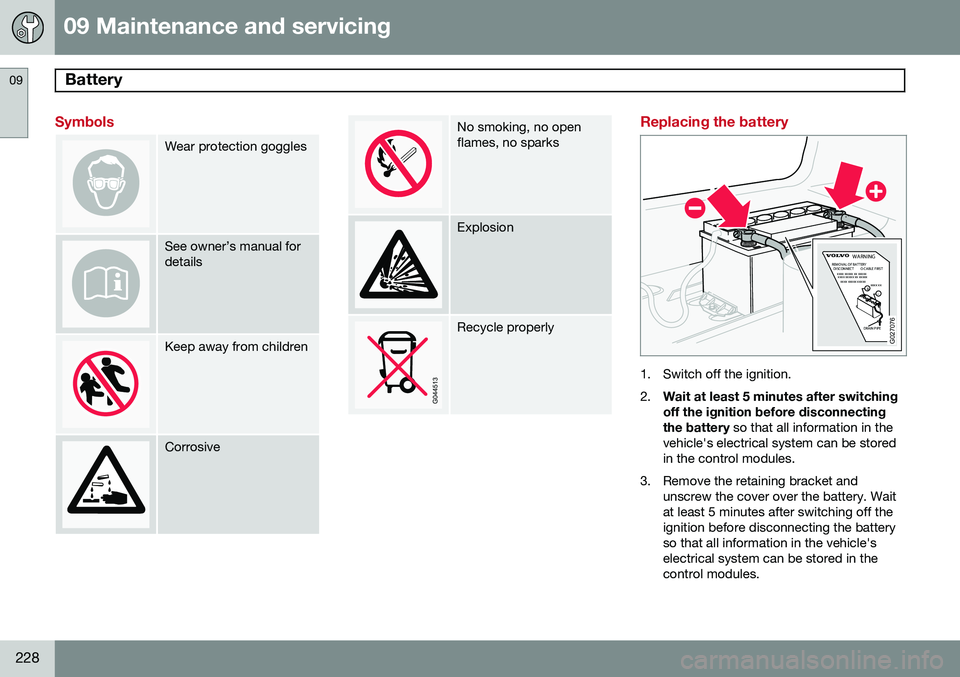
Symbols
Wear protection goggles
See owner’s manual for details
Keep away from children
Corrosive
No smoking, no open flames, no sparks
Explosion
Recycle properly
Replacing the battery
DRAIN PIPE
xxxx xxxxx xx xxxxx
DISCONNECT
REMOVAL OF BATTERYO CABLE FIRSTxxxx xxxxx xxxxxxxxx xx+-
WARNING
xxxx xxxxx xx xxxxx
G027076
1. Switch off the ignition. 2.
Wait at least 5 minutes after switching off the ignition before disconnecting the battery
so that all information in the
vehicle's electrical system can be stored in the control modules.
3. Remove the retaining bracket and unscrew the cover over the battery. Waitat least 5 minutes after switching off theignition before disconnecting the batteryso that all information in the vehicle'selectrical system can be stored in thecontrol modules.
Page 231 of 308
09 Maintenance and servicing
Battery09
229
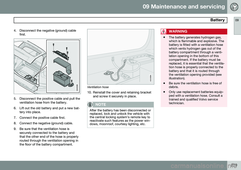
4. Disconnect the negative (ground) cable
first.
5. Disconnect the positive cable and pull theventilation hose from the battery.
6. Lift out the old battery and put a new bat- tery into place.
7. Connect the positive cable first.
8. Connect the negative (ground) cable.
9. Be sure that the ventilation hose is securely connected to the battery and that the other end of the hose is properlyrouted through the ventilation opening inthe floor of the battery compartment.
G030884
Ventilation hose
10. Reinstall the cover and retaining bracket and screw it securely in place.
NOTE
After the battery has been disconnected or replaced, lock and unlock the vehicle withthe central locking system's remote key toreactivate such features as the power win-dows, moonroof, courtesy lighting, etc.
WARNING
•The battery generates hydrogen gas, which is flammable and explosive. Thebattery is fitted with a ventilation hosewhich vents hydrogen gas out of thebattery compartment through a venti-lation opening in the bottom of thiscompartment. If the battery must bereplaced, it is essential that the ventila-tion hose is properly connected to thebattery and that it is routed throughthe ventilation opening provided (seeillustration).
• Be sure the ventilation hose is free ofdebris.
• Only use replacement batteries equip-ped with a ventilation hose. Consult atrained and qualified Volvo servicetechnician.
Page 232 of 308
09 Maintenance and servicing
Replacing bulbs 09
230* Option/accessory, for more information, see Introduction.
When replacing bulbs, keep the following points in mind:
• Never touch the glass of bulbs with your fingers. Grease and oils from your fingersvaporize in the heat and will leave adeposit on the reflector, which will dam-age it.
• The optional Active Bending Light bulbscontain trace amounts of mercury. Thesebulbs should always be disposed of by anauthorized Volvo retailer.
The following bulbs should only be replaced by a trained and qualified Volvo service tech-nician:
• Active Bending Lights (ABL)
• Daytime running lights (DRL) under the front bumper
• Turn signals and courtesy lights in theside door mirrors
• Reading lights and glove compartmentlight
• Courtesy (dome) lighting
• Rear parking lights
• Brake lights
• High-mounted brake lights
If a problem occurs with the daytime running lights (DRL) under the front bumper, the entirelamp housing will have to be replaced. If a problem occurs with the rear parkinglights or the brake lights, the entire taillighthousing will have to be replaced. See page 236 for a list of bulb specifications.
Replacing high/low beams/turn signal/parking light bulbs
WARNING
•
The engine should not be running when changing bulbs.
• If the engine has been running justprior to replacing bulbs in the head-light housing, please keep in mind thatcomponents in the engine compart-ment will be hot.
WARNING
Active Bending Lights* - due to the high voltage used by these headlights, thesebulbs should only be replaced by a trainedand qualified Volvo service technician.
G027081
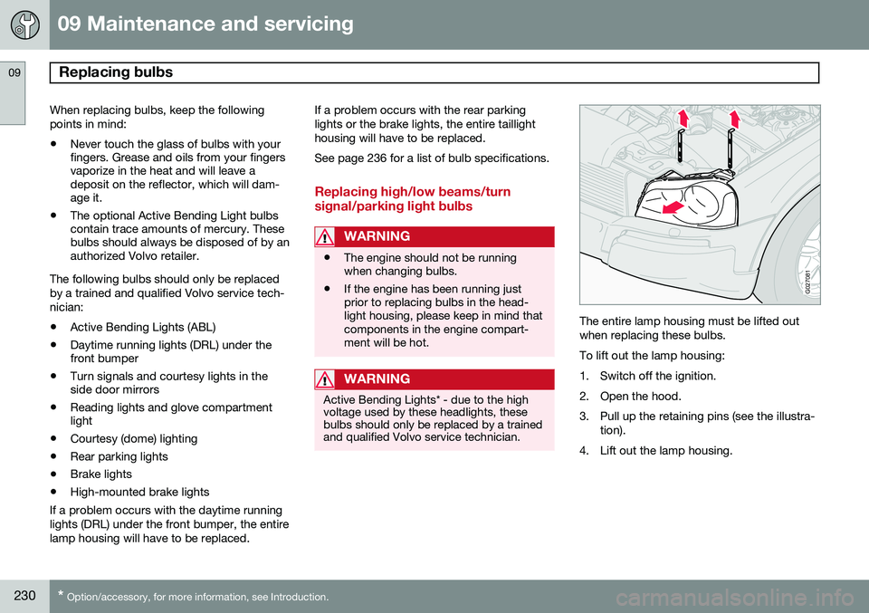
The entire lamp housing must be lifted out when replacing these bulbs. To lift out the lamp housing:
1. Switch off the ignition.
2. Open the hood.
3. Pull up the retaining pins (see the illustra-
tion).
4. Lift out the lamp housing.