VOLVO XC90 2015 Owners Manual
Manufacturer: VOLVO, Model Year: 2015, Model line: XC90, Model: VOLVO XC90 2015Pages: 570, PDF Size: 12.44 MB
Page 211 of 570
LOADING AND STORAGE
* Option/accessory, for more information, see Introduction.209
Grocery bag holder
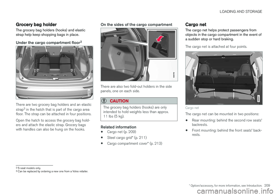
The grocery bag holders (hooks) and elastic strap help keep shopping bags in place.
Under the cargo compartment floor 2
There are two grocery bag holders and an elastic strap
3
in the hatch that is part of the cargo area
floor. The strap can be attached in four positions. Open the hatch to access the grocery bag hold- ers and attach the elastic strap. Grocery bagswith handles can also be hung on the hooks.
On the sides of the cargo compartment
There are also two fold-out holders in the side panels, one on each side.
CAUTION
The grocery bag holders (hooks) are only intended to hold weights less than approx.11 lbs (5 kg).
Related information
• Cargo net (p. 209)
• Steel cargo grid
* (p. 211)
• Cargo compartment cover
* (p. 213)
Cargo net
The cargo net helps protect passengers from objects in the cargo compartment in the event ofa sudden stop or hard braking.
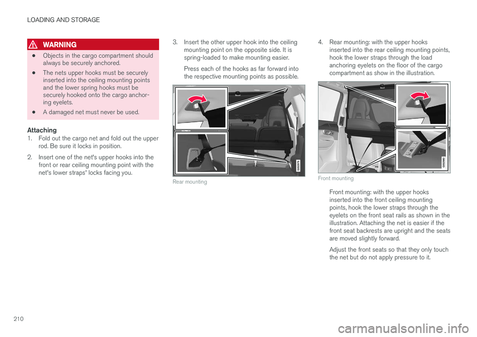
The cargo net is attached at four points.
Cargo net
The cargo net can be mounted in two positions: • Rear mounting: behind the second row seats' backrests.
• Front mounting: behind the front seats' back-rests.
2
5-seat models only.3
Can be replaced by ordering a new one from a Volvo retailer.
Page 212 of 570
LOADING AND STORAGE
210
WARNING
•Objects in the cargo compartment should always be securely anchored.
• The nets upper hooks must be securelyinserted into the ceiling mounting pointsand the lower spring hooks must besecurely hooked onto the cargo anchor-ing eyelets.
• A damaged net must never be used.
Attaching1. Fold out the cargo net and fold out the upper
rod. Be sure it locks in position.
2. Insert one of the net's upper hooks into the front or rear ceiling mounting point with the net's lower straps' locks facing you. 3. Insert the other upper hook into the ceiling
mounting point on the opposite side. It isspring-loaded to make mounting easier. Press each of the hooks as far forward into the respective mounting points as possible.
Rear mounting
4. Rear mounting: with the upper hooks inserted into the rear ceiling mounting points, hook the lower straps through the loadanchoring eyelets on the floor of the cargocompartment as show in the illustration.
Front mounting
Front mounting: with the upper hooks inserted into the front ceiling mountingpoints, hook the lower straps through theeyelets on the front seat rails as shown in theillustration. Attaching the net is easier if thefront seat backrests are upright and the seatsare moved slightly forward. Adjust the front seats so that they only touch the net but do not apply pressure to it.
Page 213 of 570
LOADING AND STORAGE
* Option/accessory, for more information, see Introduction.211
CAUTION
Pressure from the front seats against the cargo net could damage the net and/or itsbrackets.
5. Pull the lower straps taut.
Removing and storing
1. Reduce tension on the net by pressing the
button on the lower straps' respective locks and allow some slack on both sides.
2. Press in the catches and release both of the straps' hooks.
3. Remove the upper hooks from the ceiling mounting points.
4. Press the red button on the upper rod to allow it to fold.
5. Fold and roll up the net. Store the net under the cargo compartment floor.
Related information
• Cargo compartment cover
* (p. 213)
• Load anchoring eyelets (p. 212)
• Steel cargo grid
* (p. 211)
• Loading (p. 207)
Steel cargo grid
*
Your vehicle can be equipped with a steel grid that helps prevent objects in the cargo area frommoving forward into the passenger compart-ment.
The steel grid is made up of the grid itself and two separate mounting brackets. Each of thebrackets has a screw cover and there are twoplastic sleeves for the grid.
WARNING
• No one should ever be allowed to remain in the cargo compartment when the vehi-cle is moving.
• The steel grid may only be used in therear position described in this article. Theceiling attachment points above the front seats are
not intended to anchor the
steel grid.
• The third row of seats (7-seat models
*
only): these seats must be folded down when the steel grid is mounted in thevehicle.
• After being mounted, be sure that thesteel grid is securely anchored in place.
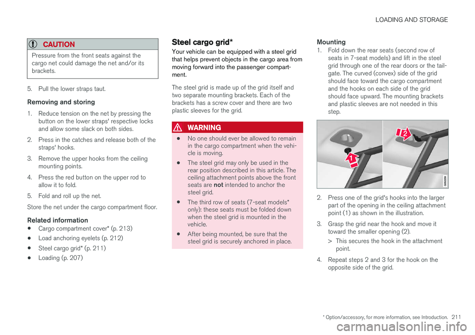
Mounting1. Fold down the rear seats (second row of
seats in 7-seat models) and lift in the steel grid through one of the rear doors or the tail-gate. The curved (convex) side of the gridshould face toward the cargo compartmentand the hooks on each side of the gridshould face upward. The mounting bracketsand plastic sleeves are not needed in thisstep.
2. Press one of the grid's hooks into the largerpart of the opening in the ceiling attachment point (1) as shown in the illustration.
3. Grasp the grid near the hook and move it toward the smaller opening (2).
> This secures the hook in the attachmentpoint.
4. Repeat steps 2 and 3 for the hook on the opposite side of the grid.
Page 214 of 570
LOADING AND STORAGE
* Option/accessory, for more information, see Introduction.
212
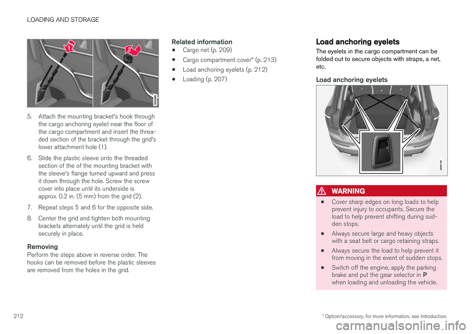
5. Attach the mounting bracket's hook through
the cargo anchoring eyelet near the floor of the cargo compartment and insert the threa-ded section of the bracket through the grid'slower attachment hole (1).
6. Slide the plastic sleeve onto the threaded section of the of the mounting bracket withthe sleeve's flange turned upward and pressit down through the hole. Screw the screwcover into place until its underside isapprox. 0.2 in. (5 mm) from the grid (2).
7. Repeat steps 5 and 6 for the opposite side.
8. Center the grid and tighten both mounting brackets alternately until the grid is held securely in place.
RemovingPerform the steps above in reverse order. Thehooks can be removed before the plastic sleevesare removed from the holes in the grid.
Related information
• Cargo net (p. 209)
• Cargo compartment cover
* (p. 213)
• Load anchoring eyelets (p. 212)
• Loading (p. 207)
Load anchoring eyelets
The eyelets in the cargo compartment can be folded out to secure objects with straps, a net,etc.
Load anchoring eyelets
WARNING
• Cover sharp edges on long loads to help prevent injury to occupants. Secure theload to help prevent shifting during sud-den stops.
• Always secure large and heavy objectswith a seat belt or cargo retaining straps.
• Always secure the load to help prevent itfrom moving in the event of sudden stops.
• Switch off the engine, apply the parking brake and put the gear selector in
P
when loading and unloading the vehicle.
Page 215 of 570
LOADING AND STORAGE
* Option/accessory, for more information, see Introduction.213
Related information
•Loading (p. 207)
Cargo compartment cover
*
The cover can be used to conceal objects in the cargo area.
Installing the cover
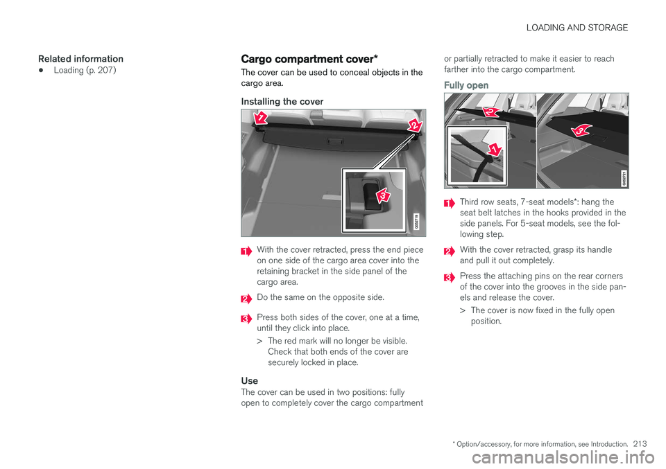
With the cover retracted, press the end piece on one side of the cargo area cover into theretaining bracket in the side panel of thecargo area.
Do the same on the opposite side.
Press both sides of the cover, one at a time, until they click into place.
> The red mark will no longer be visible. Check that both ends of the cover are securely locked in place.
UseThe cover can be used in two positions: fullyopen to completely cover the cargo compartment or partially retracted to make it easier to reachfarther into the cargo compartment.
Fully open
Third row seats, 7-seat models
*: hang the
seat belt latches in the hooks provided in the side panels. For 5-seat models, see the fol-lowing step.
With the cover retracted, grasp its handle and pull it out completely.
Press the attaching pins on the rear corners of the cover into the grooves in the side pan-els and release the cover.
> The cover is now fixed in the fully open position.
Page 216 of 570
LOADING AND STORAGE
* Option/accessory, for more information, see Introduction.
214
Partially retracted
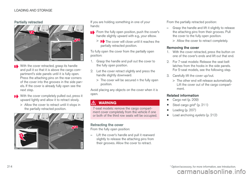
With the cover retracted, grasp its handle and pull it so that it is above the cargo com-partment's side panels until it is fully open.Press the attaching pins on the rear cornersof the cover into the grooves in the side pan-els. If the cover is already fully open see thenext step.
With the cover completely pulled out, press it upward lightly and allow it to retract slowly.
> Allow the cover to retract until it stops in
the partially retracted position.
If you are holding something in one of your hands:
From the fully open position, push the cover's handle slightly upward with e.g., your elbow. >
The cover will close until it reaches the
partially retracted position.
To fully open the cover from the partially open position:
1. Grasp the handle and pull out the cover to the fully open position.
2. Let the cover retract slightly and press the handle slightly downward.
> The cover will be secured n the fully openposition.
Avoid placing any objects on the cover when it is open.
WARNING
7-seat models: remove the cargo compart- ment cover completely from the vehicle if oneor both of the third row seats will be occupied.
Retracting the coverFrom the fully open position:
–Lift the cover's handle and pull it rearward slightly to release the attaching pins fromtheir grooves. Allow the cover to retract. From the partially retracted position:
–Grasp the handle and lift it slightly to release the attaching pins from their grooves. Pullthe cover to the fully open position.
> Allow the cover to retract completely.
Removing the cover1. With the cover retracted, press the button on
one of the cover's ends and lift out that end.
2. For 7-seat models: Release the seat belt latches from the hooks in the side panels. For 5-seat models, see the following step.
3. Carefully lift the cover up/out. > The other end will release automatically.Lift the cover out of the cargo compart-ment.
Related information
• Cargo net (p. 209)
• Steel cargo grid
* (p. 211)
• Loading (p. 207)
• Load anchoring eyelets (p. 212)
Page 217 of 570
L O C K S A N D A L A R M
Page 218 of 570

LOCKS AND ALARM
* Option/accessory, for more information, see Introduction.
216
Locks and remote keys
The vehicle can be locked and unlocked in vari- ous ways and there are several types of remotekeys that can be used. These keys can also belinked to a driver profile, which contains vehicle-related settings that have been stored.
Locking/unlocking/opening/closingThe vehicle can be locked/unlocked from the passenger compartment, using the buttons onthe remote key or by using the optional PassiveEntry system where it is only necessary to have akey in your possession to lock or unlock thedoors. On models equipped with a power tailgate *, the
tailgate can be opened/closed by moving your foot under a sensor * beneath the rear bumper.
If for any reason a remote key does not function properly, it may be necessary to replace its bat-teries but the vehicle can always be locked orunlocked manually using the remote key'sdetachable key blade.
Remote keyThe remote key does not have to be physicallyhandled in order to start the engine because thevehicle is equipped with the standard PassiveStart system (the key only needs to be in thefront part of the passenger compartment). If thevehicle is equipped with the optional PassiveEntry system that enables keyless entry and start, the key can be anywhere in the vehicle when theengine is started. Models with Passive Entry
* also have an extra,
smaller key without buttons called a Key Tag. A special restricted Red Key makes it possible to limit some of the vehicle's functionality, such asby setting a maximum speed or limiting the maxi-mum volume from the infotainment system'sspeakers. The various keys can also be linked to driver pro- files, which make it possible to store differentpersonal preferences (settings) in the vehicle. Additional keys can be ordered from a Volvo retailer.
Related information
• Immobilizer (p. 221)
• Alarm (p. 216)
• Child safety locks (p. 218)
• Remote key (p. 224)
• Restricted key
* (p. 226)
• Foot movement tailgate operation
* (p. 228)
• Locking/unlocking from inside the vehicle (p. 231)
• Locking/unlocking from outside the vehicle(p. 232)
• Locking/unlocking the tailgate (p. 233)
• Starting the engine (p. 356)
Alarm
The alarm system provides a warning if an attempt is made to break into the vehicle.
The following conditions will trigger the alarm:
• a door/hood/tailgate are opened
• the battery is disconnected
• the alarm siren is disconnected
If a problem is detected in the alarm system, a message will be displayed in the instrumentpanel. Do not attempt to repair any of the components in the alarm system yourself; this could affect theinsurance policy on the vehicle. Contact a trainedand qualified Volvo service technician.
NOTE
One of the alarm sensors, which is sensitive to metallic objects, is located under the tunnelconsole cup holders. Avoid leaving coins,keys, etc., in the cup holders because theymay inadvertently trigger the alarm.
Page 219 of 570
LOCKS AND ALARM
* Option/accessory, for more information, see Introduction.217
Arming the alarm
–Lock the vehicle by pressing the remote key's lock button, pressing the outer indenta- tion for locking on one of the door handles1
or by pressing the tailgate's rubberized pres-sure plate 1
.
If the vehicle is equipped with a power tail- gate *, the button on the lower edge of the
tailgate can also be used to lock the vehicle and arm the alarm.
Disarming the alarm
–Unlock the vehicle by pressing the remote key's unlock button, pressing the pressure-sensitive area on the inside of one of the door handles 1
or by pressing the tailgate's
rubberized pressure plate 1
.
Turning off a triggered (sounding) alarm
–Press the remote key's unlock button or put the ignition in mode I by turning the start
knob to START and releasing it.
Alarm signalsThe following occurs if the alarm has been trig- gered:
• A siren will sound for 30 seconds or until the alarm is turned off
• Passenger compartment lighting illuminatesand all turn signals flash for 5 minutes oruntil the alarm is turned off If the door that triggered the alarm is left open,
the alarm cycle will be repeated 10 times.
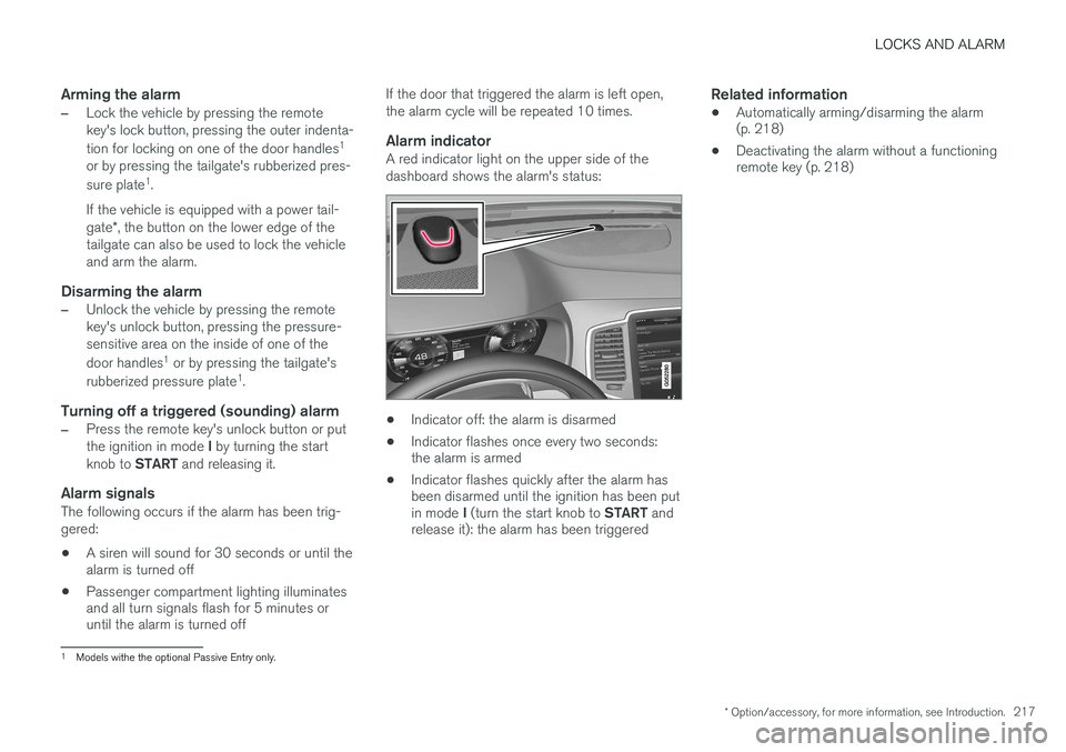
Alarm indicatorA red indicator light on the upper side of the dashboard shows the alarm's status:
• Indicator off: the alarm is disarmed
• Indicator flashes once every two seconds: the alarm is armed
• Indicator flashes quickly after the alarm hasbeen disarmed until the ignition has been put in mode
I (turn the start knob to START and
release it): the alarm has been triggered
Related information
• Automatically arming/disarming the alarm (p. 218)
• Deactivating the alarm without a functioningremote key (p. 218)
1
Models withe the optional Passive Entry only.
Page 220 of 570
LOCKS AND ALARM
* Option/accessory, for more information, see Introduction.
218
Automatically arming/disarming the alarm
Automatically arming the alarm helps prevent inadvertently leaving the vehicle without alarmprotection.
If the vehicle has been unlocked with the remote key (and the alarm has been disarmed) but nodoor or the tailgate has been opened within2 minutes, the vehicle will automatically relockand the alarm will re-arm. In certain markets, the alarm will be re-armed automatically after a slight delay after the driver'sdoor has been opened and closed without beinglocked.
Related information
• Alarm (p. 216)
• Deactivating the alarm without a functioning remote key (p. 218)
Deactivating the alarm without a functioning remote key
If the remote key is not functioning properly, the alarm can be turned off and the vehicle can bestarted as follows:
1. Unlock and open the driver's door with the detachable key blade.
> This will trigger the alarm.
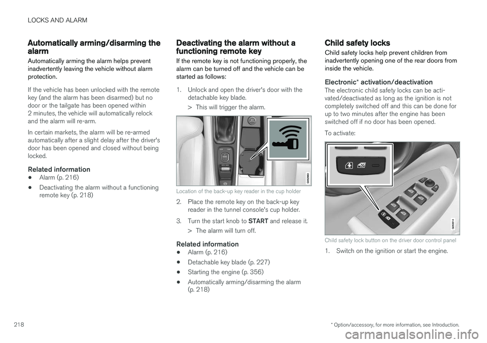
Location of the back-up key reader in the cup holder
2. Place the remote key on the back-up keyreader in the tunnel console's cup holder.
3. Turn the start knob to START and release it.
> The alarm will turn off.
Related information
• Alarm (p. 216)
• Detachable key blade (p. 227)
• Starting the engine (p. 356)
• Automatically arming/disarming the alarm (p. 218)
Child safety locks
Child safety locks help prevent children from inadvertently opening one of the rear doors frominside the vehicle.
Electronic * activation/deactivationThe electronic child safety locks can be acti- vated/deactivated as long as the ignition is notcompletely switched off and this can be done forup to two minutes after the engine has beenswitched off if no door has been opened. To activate:
Child safety lock button on the driver door control panel
1. Switch on the ignition or start the engine.