VOLVO XC90 2015 Owners Manual
Manufacturer: VOLVO, Model Year: 2015, Model line: XC90, Model: VOLVO XC90 2015Pages: 570, PDF Size: 12.44 MB
Page 351 of 570
STARTING AND DRIVING
349
To refuel:
1. Open the fuel filler door. Do not refuel with
the engine running 3
2. Insert the pump's nozzle into the fuel filler pipe's opening as far as possible (see the
illustration).
3. Avoid overfilling the fuel tank. Do not press the handle on the filler nozzle after it has stopped pumping. Too much fuel in the tankin hot weather conditions can cause the fuelto overflow. Overfilling could also cause dam-age to the emission control systems.
CAUTION
Avoid spilling gasoline during refueling. In addition to causing damage to the environ-ment, gasolines containing alcohol can causedamage to painted surfaces, which may notbe covered under the New Vehicle LimitedWarranty.
Related information
• Fuel (p. 346)
• Octane rating (p. 347)
Emission controls
Three-way catalytic converter
•Keep your engine properly tuned. Certain engine malfunctions, particularly involving theelectrical, fuel or distributor ignition systems,may cause unusually high three-way catalyticconverter temperatures. Do not continue tooperate your vehicle if you detect enginemisfire, noticeable loss of power or otherunusual operating conditions, such as engineoverheating or backfiring. A properly tunedengine will help avoid malfunctions thatcould damage the three-way catalytic con-verter.
• Do not park your vehicle over combustiblematerials, such as grass or leaves, which cancome into contact with the hot exhaust sys-tem and cause such materials to ignite undercertain wind and weather conditions.
• Excessive starter cranking (in excess of oneminute), or an intermittently firing or floodedengine can cause three-way catalytic con-verter or exhaust system overheating.
• Remember that tampering or unauthorizedmodifications to the engine, the Engine Con-trol Module, or the vehicle may be illegal andcan cause three-way catalytic converter orexhaust system overheating. This includes:altering fuel injection settings or compo-nents, altering emission system components or location or removing components, and/orrepeated use of leaded fuel.NOTE
Unleaded fuel is required for vehicles with three-way catalytic converters.
Heated oxygen sensorsThe heated oxygen sensors monitor the oxygen content of the exhaust gases. Readings are fedinto a control module that continuously monitorsengine functions and controls fuel injection. Theratio of fuel to air into the engine is continuouslyadjusted for efficient combustion to help reduceharmful emissions.
Related information
•
Octane rating (p. 347)
3
If the engine is running when the vehicle is refueled, the Check Engine Light (malfunction indicator lamp) may indicate a fault. However, your vehicle's performance will not be affected.
Page 352 of 570
STARTING AND DRIVING
350
Jump startingFollow the instructions provided here to jump start your vehicle or to jump start another vehi-cle.
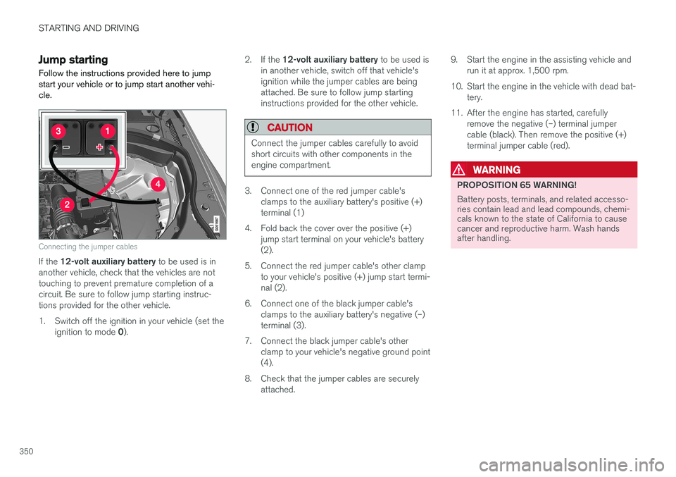
Connecting the jumper cables
If the 12-volt auxiliary battery to be used is in
another vehicle, check that the vehicles are not touching to prevent premature completion of acircuit. Be sure to follow jump starting instruc-tions provided for the other vehicle.
1. Switch off the ignition in your vehicle (set the
ignition to mode 0). 2.
If the 12-volt auxiliary battery to be used is
in another vehicle, switch off that vehicle's ignition while the jumper cables are beingattached. Be sure to follow jump startinginstructions provided for the other vehicle.
CAUTION
Connect the jumper cables carefully to avoid short circuits with other components in theengine compartment.
3. Connect one of the red jumper cable's clamps to the auxiliary battery's positive (+) terminal (1)
4. Fold back the cover over the positive (+) jump start terminal on your vehicle's battery(2).
5. Connect the red jumper cable's other clamp to your vehicle's positive (+) jump start termi-nal (2).
6. Connect one of the black jumper cable's clamps to the auxiliary battery's negative (–)terminal (3).
7. Connect the black jumper cable's other clamp to your vehicle's negative ground point(4).
8. Check that the jumper cables are securely attached. 9. Start the engine in the assisting vehicle and
run it at approx. 1,500 rpm.
10. Start the engine in the vehicle with dead bat- tery.
11. After the engine has started, carefully remove the negative (–) terminal jumpercable (black). Then remove the positive (+)terminal jumper cable (red).
WARNING
PROPOSITION 65 WARNING! Battery posts, terminals, and related accesso- ries contain lead and lead compounds, chemi-cals known to the state of California to causecancer and reproductive harm. Wash handsafter handling.
Page 353 of 570
STARTING AND DRIVING
351
WARNING
•Do not connect the jumper cable to any part of the fuel system or to any movingparts. Avoid touching hot manifolds.
• Batteries generate hydrogen gas, whichis flammable and explosive.
• Battery fluid contains sulfuric acid. Do notallow battery fluid to contact eyes, skin,fabrics or painted surfaces. If contactoccurs, flush the affected area immedi-ately with water. Obtain medical helpimmediately if eyes are affected.
• Never expose the battery to open flameor electric spark.
• Do not smoke near the battery.
• Failure to follow the instructions for jumpstarting can lead to injury.
Related information
• Ignition modes (p. 355)
• Starting the engine (p. 356)
• Turning the engine off (p. 359)
Driving with a trailer
When towing a trailer, always observe the legal requirements of the state/province.
• All Volvo models are equipped with energy- absorbing shock-mounted bumpers. Trailerhitch installation should not interfere with theproper operation of this bumper system.
Trailer towing does not normally present any par- ticular problems, but take into consideration:
• Increase tire pressure to recommended full pressure.
• When your vehicle is new, avoid towing heavytrailers during the first 620 miles (1,000 km).
• Maximum speed when towing a trailer:50 mph (80 km/h).
• Engine and transmission are subject toincreased loads. Therefore, engine coolanttemperature should be closely watched whendriving in hot climates or hilly terrain. Use alower gear and turn off the air conditioner ifthe temperature gauge needle enters the redrange.
• If the automatic transmission begins to over-heat, a message will be displayed in the textwindow.
• Avoid overload and other abusive operation.
• Hauling a trailer affects handling, durability,and economy.
• It is necessary to balance trailer brakes withthe towing vehicle brakes to provide a safe stop (check and observe state/local regula-tions).
• Do not connect the trailer's brake systemdirectly to the vehicle's brake system.
• More frequent vehicle maintenance isrequired.
• Remove the ball holder when the hitch is notbeing used.
NOTE
• When parking the vehicle with a trailer on a hill, apply the parking brake before put- ting the gear selector in
P. Always follow
the trailer manufacturer's recommenda- tions for wheel chocking.
• When starting on a hill, put the gear selector in
D before releasing the parking
brake.
• If you use the manual (Geartronic) shift positions while towing a trailer, make surethe gear you select does not put toomuch strain on the engine (using toohigh a gear).
• The drawbar assembly/trailer hitch maybe rated for trailers heavier than the vehi-cle is designed to tow. Please adhere toVolvo's recommended trailer weights.
• Avoid driving with a trailer on inclines ofmore than 15%.
Page 354 of 570
STARTING AND DRIVING
* Option/accessory, for more information, see Introduction.
352
CAUTION
The maximum trailer weights listed are only applicable for altitudes up to 3,280 ft(1000 m) above sea level. With increasingaltitude the engine power and therefore thecar's climbing ability are impaired because ofthe reduced air density, so the maximumtrailer weight has to be reduced accordingly.The weight of the vehicle and trailer must bereduced by 10% for every further 3,280 ft(1000 m) (or part thereof). When towing5,950 lbs (2,700kg) hill inclination is restric-ted to 14%.
WARNING
• Bumper-attached trailer hitches must not be used on Volvos, nor should safetychains be attached to the bumper.
• Trailer hitches attaching to the vehiclerear axle must not be used.
• Never connect a trailer's hydraulic brakesystem directly to the vehicle brake sys-tem, nor a trailer's lighting system directlyto the vehicle lighting system. Consultyour nearest authorized Volvo retailer forcorrect installation.
• When towing a trailer, the trailer's safetychains or wire must be correctly fastenedto the attachment points provided in thetrailer hitch on the vehicle. The safetychain or wire must never be fastened toor wound around the towing ball.
Trailer cableAn adapter is required if the vehicle's trailer hitch has a 13-pin connector and the trailer has 7 pins.Use an adapter cable approved by Volvo. Makesure the cable does not drag on the ground.
Self-leveling suspension
*With this system, the rear suspension maintains aconstant level, regardless of the load in the cargocompartment (up to the max. permissible load).When the engine is not running, the rear of thevehicle sinks down slightly, which is normal.
Related information
•Detachable trailer hitch (p. 353)
• Trailer Stability Assist (TSA) (p. 354)
• Weights (p. 539)
Page 355 of 570
STARTING AND DRIVING
353
Detachable trailer hitch
Volvo recommends the use of Volvo trailer hitches that are specially designed for the vehi-cle.
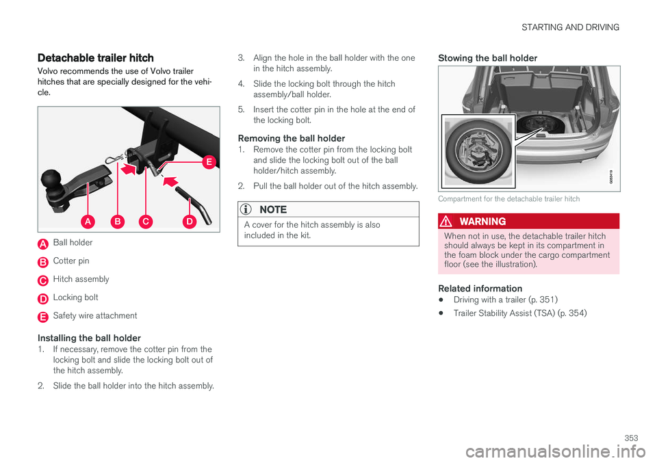
Ball holder
Cotter pin
Hitch assembly
Locking bolt
Safety wire attachment
Installing the ball holder1. If necessary, remove the cotter pin from the locking bolt and slide the locking bolt out of the hitch assembly.
2. Slide the ball holder into the hitch assembly. 3. Align the hole in the ball holder with the one
in the hitch assembly.
4. Slide the locking bolt through the hitch assembly/ball holder.
5. Insert the cotter pin in the hole at the end of the locking bolt.
Removing the ball holder1. Remove the cotter pin from the locking boltand slide the locking bolt out of the ballholder/hitch assembly.
2. Pull the ball holder out of the hitch assembly.
NOTE
A cover for the hitch assembly is also included in the kit.
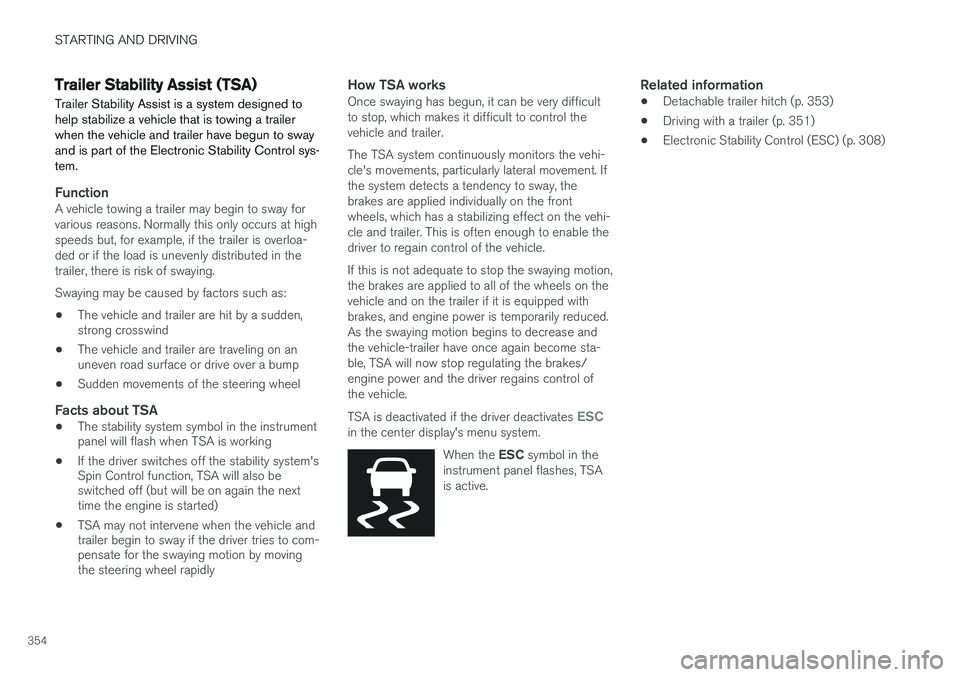
Stowing the ball holder
Compartment for the detachable trailer hitch
WARNING
When not in use, the detachable trailer hitch should always be kept in its compartment inthe foam block under the cargo compartmentfloor (see the illustration).
Related information
• Driving with a trailer (p. 351)
• Trailer Stability Assist (TSA) (p. 354)
Page 356 of 570
STARTING AND DRIVING
354
Trailer Stability Assist (TSA)
Trailer Stability Assist is a system designed to help stabilize a vehicle that is towing a trailerwhen the vehicle and trailer have begun to swayand is part of the Electronic Stability Control sys-tem.
FunctionA vehicle towing a trailer may begin to sway for various reasons. Normally this only occurs at highspeeds but, for example, if the trailer is overloa-ded or if the load is unevenly distributed in thetrailer, there is risk of swaying. Swaying may be caused by factors such as:
• The vehicle and trailer are hit by a sudden, strong crosswind
• The vehicle and trailer are traveling on anuneven road surface or drive over a bump
• Sudden movements of the steering wheel
Facts about TSA
• The stability system symbol in the instrumentpanel will flash when TSA is working
• If the driver switches off the stability system'sSpin Control function, TSA will also beswitched off (but will be on again the nexttime the engine is started)
• TSA may not intervene when the vehicle andtrailer begin to sway if the driver tries to com-pensate for the swaying motion by movingthe steering wheel rapidly
How TSA worksOnce swaying has begun, it can be very difficult to stop, which makes it difficult to control thevehicle and trailer. The TSA system continuously monitors the vehi- cle's movements, particularly lateral movement. Ifthe system detects a tendency to sway, thebrakes are applied individually on the frontwheels, which has a stabilizing effect on the vehi-cle and trailer. This is often enough to enable thedriver to regain control of the vehicle. If this is not adequate to stop the swaying motion, the brakes are applied to all of the wheels on thevehicle and on the trailer if it is equipped withbrakes, and engine power is temporarily reduced.As the swaying motion begins to decrease andthe vehicle-trailer have once again become sta-ble, TSA will now stop regulating the brakes/engine power and the driver regains control ofthe vehicle. TSA is deactivated if the driver deactivates
ESCin the center display's menu system.
When the ESC symbol in the
instrument panel flashes, TSA is active.
Related information
• Detachable trailer hitch (p. 353)
• Driving with a trailer (p. 351)
• Electronic Stability Control (ESC) (p. 308)
Page 357 of 570
STARTING AND DRIVING
* Option/accessory, for more information, see Introduction.355
Ignition modes
The vehicle's ignition can be put in various modes (levels) to make different functions availa-ble.
The vehicle's ignition has 3 modes: 0, I, and II
that can be used to operate various functions without starting the engine. The following tableshows examples of which functions are availablein the respective modes.
ModeFunctions available
0• The odometer, clock and tem- perature gauge are illuminated
• Power seats
* can be adjusted
• The power windows can be oper-ated
• The 12-volt socket in the cargocompartment can be used
• The center display is activatedand can be used
• The infotainment system can beused for a limited time
In this mode, certain functions can only be used for a limited time to helpminimize battery drain
I• The laminated panoramic roof
*,
power seats */windows,12-volt
sockets in the passenger com- partment, Bluetooth, navigation system *, climate system blower,
windshield wipers can be oper- ated
• The infotainment system will start(if it was started when the ignitionwas switched off)
ModeFunctions available
II• The headlights illuminate
• Warning/indicator lights illumi- nate for 5 seconds
• A number of other functions willalso be activated. However, the heated seats
* and heated rear
window functions can only be activated when the engine is run-ning.
This mode should only be used for very short periods to help avoiddraining the battery.
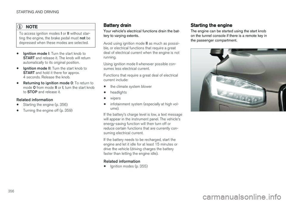
Selecting an ignition mode
Start knob in the tunnel console
• Ignition mode 0
: unlock the vehicle and
keep the remote key in the passenger's com- partment.
Page 358 of 570
STARTING AND DRIVING
356
NOTE
To access ignition modes I or II without star-
ting the engine, the brake pedal must not be
depressed when these modes are selected.
• Ignition mode I
: Turn the start knob to
START and release it. The knob will return
automatically to its original position.
• Ignition mode II
: Turn the start knob to
START and hold it there for approx.
4 seconds. Release the knob.
• Returning to ignition mode 0
: To return to
mode 0 from mode II or I, turn the start knob
to STOP and release it.
Related information
•Starting the engine (p. 356)
• Turning the engine off (p. 359)
Battery drain Your vehicle's electrical functions drain the bat- tery to varying extents.
Avoid using ignition mode
II as much as posssi-
ble, or electrical functions that require a great deal of electrical current when the engine is notrunning. Using ignition mode I whenever possible con-
sumes less electrical current. Functions that require a great deal of electrical current include:
• the climate system blower
• headlights
• wipers
• infotainment system (especially at high vol- ume).
If the battery's charge level is low, a text message will appear in the instrument panel. The vehicle'senergy-saving function will then turn off orreduce certain functions that are currently con-suming electrical current. If the battery needs to be recharged, start the engine and let it idle for at least 15 minutes ordrive the vehicle (driving charges the batteryfaster than letting the engine idle).
Related information
• Ignition modes (p. 355)
Starting the engine
The engine can be started using the start knob on the tunnel console if there is a remote key inthe passenger compartment.
Page 359 of 570
STARTING AND DRIVING
357
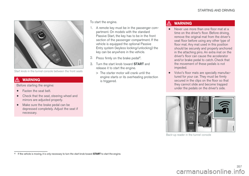
Start knob in the tunnel console between the front seats
WARNING
Before starting the engine:• Fasten the seat belt.
• Check that the seat, steering wheel and mirrors are adjusted properly.
• Make sure the brake pedal can bedepressed completely. Adjust the seat ifnecessary. To start the engine.
1. A remote key must be in the passenger com-
partment. On models with the standard Passive Start, the key has to be in the frontsection of the passenger compartment. If thevehicle is equipped the optional PassiveEntry system (keyless locking/unlocking) thekey can be anywhere in the vehicle.
2. Press firmly on the brake pedal 4
.
3. Turn the start knob toward START and
release it to start the engine.
> The starter motor will crank until the engine starts or its overheating protection is triggered.
WARNING
• Never use more than one floor mat at a time on the driver's floor. Before driving,remove the original mat from the driver'sseat floor before using any other type offloor mat. Any mat used in this positionshould be securely and properly anchoredin the attaching pins. An extra mat on thedriver's floor can cause the acceleratorand/or brake pedal to catch. Check thatthe movement of these pedals is notimpeded.
• Volvo's floor mats are specially manufac-tured for your car. They must be firmlysecured in the clips on the floor so thatthey cannot slide and become trappedunder the pedals on the driver's side.
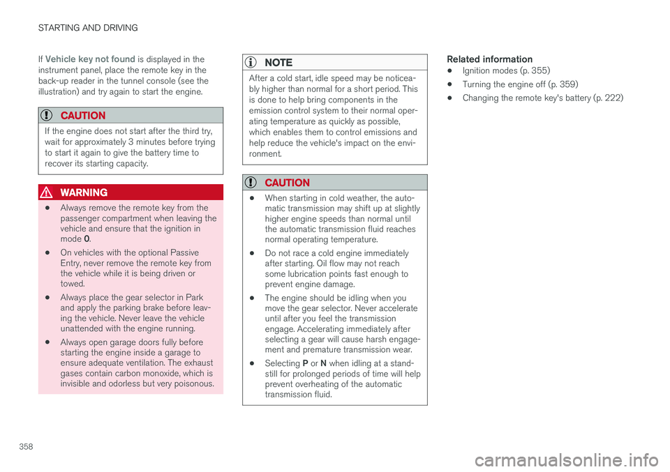
Back-up reader in the tunnel console
4
If the vehicle is moving, it is only necessary to turn the start knob toward START to start the engine.
Page 360 of 570
STARTING AND DRIVING
358If
Vehicle key not found is displayed in the
instrument panel, place the remote key in the back-up reader in the tunnel console (see theillustration) and try again to start the engine.
CAUTION
If the engine does not start after the third try, wait for approximately 3 minutes before tryingto start it again to give the battery time torecover its starting capacity.
WARNING
• Always remove the remote key from the passenger compartment when leaving thevehicle and ensure that the ignition in mode
0.
• On vehicles with the optional Passive Entry, never remove the remote key fromthe vehicle while it is being driven ortowed.
• Always place the gear selector in Parkand apply the parking brake before leav-ing the vehicle. Never leave the vehicleunattended with the engine running.
• Always open garage doors fully beforestarting the engine inside a garage toensure adequate ventilation. The exhaustgases contain carbon monoxide, which isinvisible and odorless but very poisonous.
NOTE
After a cold start, idle speed may be noticea- bly higher than normal for a short period. Thisis done to help bring components in theemission control system to their normal oper-ating temperature as quickly as possible,which enables them to control emissions andhelp reduce the vehicle's impact on the envi-ronment.
CAUTION
•
When starting in cold weather, the auto- matic transmission may shift up at slightlyhigher engine speeds than normal untilthe automatic transmission fluid reachesnormal operating temperature.
• Do not race a cold engine immediatelyafter starting. Oil flow may not reachsome lubrication points fast enough toprevent engine damage.
• The engine should be idling when youmove the gear selector. Never accelerateuntil after you feel the transmissionengage. Accelerating immediately afterselecting a gear will cause harsh engage-ment and premature transmission wear.
• Selecting
P or N when idling at a stand-
still for prolonged periods of time will helpprevent overheating of the automatictransmission fluid.
Related information
• Ignition modes (p. 355)
• Turning the engine off (p. 359)
• Changing the remote key's battery (p. 222)