ECU VOLVO XC90 T8 2017 Owner´s Manual
[x] Cancel search | Manufacturer: VOLVO, Model Year: 2017, Model line: XC90 T8, Model: VOLVO XC90 T8 2017Pages: 580, PDF Size: 10.37 MB
Page 93 of 580
SAFETY
}}}}
91
Related information
•Child restraints (p. 81)
• ISOFIX/LATCH lower anchors (p. 89)
• Occupant weight sensor (p. 73)
Top tether anchors
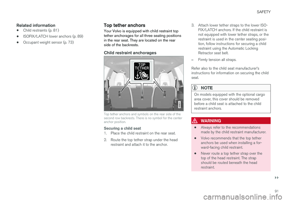
Your Volvo is equipped with child restraint top tether anchorages for all three seating positionsin the rear seat. They are located on the rearside of the backrests.
Child restraint anchorages
Top tether anchors and symbols on the rear side of the second row backrests. There is no symbol for the centeranchor position.
Securing a child seat
1. Place the child restraint on the rear seat.
2. Route the top tether strap under the head restraint and attach it to the anchor. 3. Attach lower tether straps to the lower ISO-
FIX/LATCH anchors. If the child restraint is not equipped with lower tether straps, or therestraint is used in the center seating posi-tion, follow instructions for securing a childrestraint using the Automatic LockingRetractor seat belt.
–Firmly tension all straps.
Refer also to the child seat manufacturer's instructions for information on securing the childseat.
NOTE
On models equipped with the optional cargo area cover, this cover should be removedbefore a child seat is attached to the childrestraint anchors.
WARNING
• Always refer to the recommendations made by the child restraint manufacturer.
• Volvo recommends that the top tetheranchors be used when installing a for-ward-facing child restraint.
• Never route a top tether strap over thetop of the head restraint. The strapshould be routed beneath the headrestraint.
Page 94 of 580
||
SAFETY
* Option/accessory.
92
• Child restraint anchorages are designed to withstand only those loads imposed bycorrectly fitted child restraints. Under nocircumstances are they to be used foradult seat belts or harnesses. The ancho-rages are not able to withstand excessiveforces on them in the event of collision iffull harness seat belts or adult seat beltsare installed to them. An adult who uses abelt anchored in a child restraint anchor-age runs a great risk of suffering severeinjuries should a collision occur.
• Do not install rear speakers that requirethe removal of the top tether anchors orinterfere with the proper use of the toptether strap.
Related information
• Child safety (p. 79)
• Child restraints (p. 81)
Integrated booster cushion
*
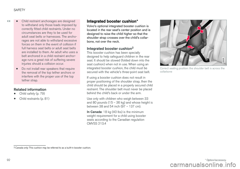
Volvo's optional integrated booster cushion is located in the rear seat's center position and isdesigned to raise the child higher so that theshoulder strap crosses over the child's collar-bone, not over the neck.
Integrated booster cushion 2This booster cushion has been specially designed to help safeguard children in the rearseat. It should be stowed (folded down into theseat cushion) when not in use. When using anintegrated booster cushion, the child must besecured with the vehicle's three-point seat belt. If using a booster cushion does not result in proper positioning of the shoulder strap, then thechild should be placed in a properly secured childrestraint. The shoulder belt must never be placedbehind the child's back or under the arm. Use only with children who weigh between 33 and 80 pounds (15 – 36 kg) and whose height isbetween 38 and 54 inch (97 – 137 cm). In Canada
: 18 kg (40 lbs) is the minimum
weight requirement for a child using booster seats according to the Canadian regulationCMVSS 213.4
Correct seating position: the shoulder belt is across the collarbone
2 Canada only: This cushion may be referred to as a built-in booster cushion.
Page 104 of 580
INSTRUMENTS AND CONTROLS
* Option/accessory.
102
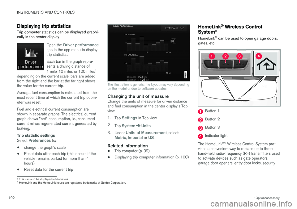
Displaying trip statistics Trip computer statistics can be displayed graphi- cally in the center display.
Open the Driver performanceapp in the app menu to display trip statistics. Each bar in the graph repre- sents a driving distance of 1 mile, 10 miles or 100 miles 1
depending on the current scale; bars are added from the right and the bar at the far right showsthe value for the current trip. Average fuel consumption is calculated from the most recent time at which the current trip odom-eter was reset. Fuel and electrical current consumption are shown in separate graphs. The electrical currentgraph shows "net" consumption, i.e., consumedcurrent minus regenerated current generated bybraking.
Trip statistic settings
Select Preferences to:
• change the graph's scale
• Reset data after each trip (this occurs if the vehicle remains parked for more than 4hours)
• Reset data for the current trip
The illustration is generic; the layout may vary depending on the model or due to software updates
Changing the unit of measureChange the units of measure for driven distance and fuel consumption in the center display's Topview. 1.
Tap
Settings in Top view.
2. Tap
SystemUnits.
3. Under
Units of Measurement, select:Metric, Imperial or US.
Related information
• Trip computer (p. 99)
• Displaying trip computer information (p. 100)
HomeLink ®
Wireless Control
System *
HomeLink ®
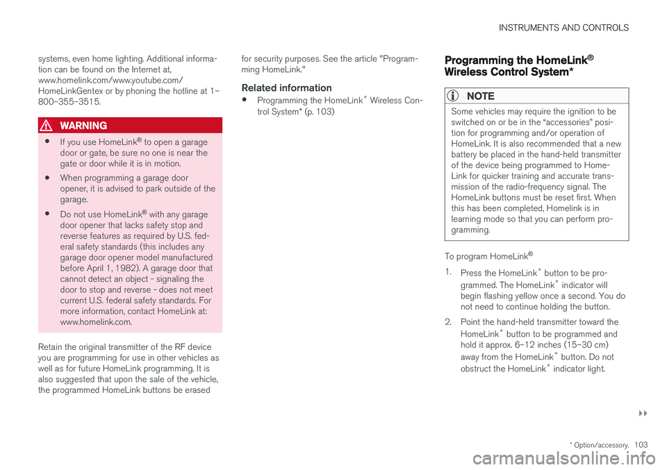
can be used to open garage doors,
gates, etc.
Button 1
Button 2
Button 3
Indicator light
The HomeLink ®
2
Wireless Control System pro-
vides a convenient way to replace up to three hand-held radio-frequency (RF) transmitters usedto activate devices such as gate operators,garage door openers, entry door locks, security
1 This can also be displayed in kilometers.
2 HomeLink and the HomeLink house are registered trademarks of Gentex Corporation.
Page 105 of 580
INSTRUMENTS AND CONTROLS
}}
* Option/accessory.103
systems, even home lighting. Additional informa- tion can be found on the Internet at,www.homelink.com/www.youtube.com/HomeLinkGentex or by phoning the hotline at 1–800–355–3515.
WARNING
•
If you use HomeLink ®
to open a garage
door or gate, be sure no one is near the gate or door while it is in motion.
• When programming a garage dooropener, it is advised to park outside of thegarage.
• Do not use HomeLink ®
with any garage
door opener that lacks safety stop andreverse features as required by U.S. fed-eral safety standards (this includes anygarage door opener model manufacturedbefore April 1, 1982). A garage door thatcannot detect an object - signaling thedoor to stop and reverse - does not meetcurrent U.S. federal safety standards. Formore information, contact HomeLink at:www.homelink.com.
Retain the original transmitter of the RF deviceyou are programming for use in other vehicles aswell as for future HomeLink programming. It isalso suggested that upon the sale of the vehicle,the programmed HomeLink buttons be erased for security purposes. See the article "Program-ming HomeLink."
Related information
•
Programming the HomeLink ®
Wireless Con-
trol System * (p. 103)
Programming the HomeLink ®
Wireless Control System *
NOTE
Some vehicles may require the ignition to be switched on or be in the “accessories” posi-tion for programming and/or operation ofHomeLink. It is also recommended that a newbattery be placed in the hand-held transmitterof the device being programmed to Home-Link for quicker training and accurate trans-mission of the radio-frequency signal. TheHomeLink buttons must be reset first. Whenthis has been completed, Homelink is inlearning mode so that you can perform pro-gramming.
To program HomeLink®
1. Press the HomeLink ®
button to be pro-
grammed. The HomeLink ®
indicator will
begin flashing yellow once a second. You do not need to continue holding the button.
2. Point the hand-held transmitter toward the HomeLink ®
button to be programmed and
hold it approx. 6–12 inches (15–30 cm) away from the HomeLink ®
button. Do not
obstruct the HomeLink ®
indicator light.
Page 107 of 580
INSTRUMENTS AND CONTROLS
}}
105
Gate Operator/Canadian Programming
Canadian radio-frequency laws require transmit- ter signals to “time-out” (or quit) after severalseconds of transmission – which may not be longenough for HomeLink to pick up the signal dur-ing programming. Similar to this Canadian law,some U.S. gate operators are designed to “time-out” in the same manner. If you live in Canada or you are having difficulties programming a gate operator or garage dooropener by using the “Programming” procedures, replace “Programming HomeLink” step 3 with the following:
• Continue to press and hold the HomeLink button while you
press and release - every
two seconds (“cycle”) your hand-held trans-
mitter until the HomeLink indicator light changes from a slow to a rapidly blinkinglight. Now you may release both the Home-Link and hand-held transmitter buttons.
Proceed with “Programming” step 4 to complete.
Using HomeLink ®When programming has been completed, HomeLink
®
can be used instead of the original
remote controls. To operate, press and hold the programmed HomeLink ®
button until the trained device begins
to operate 3
(this may take several seconds). The indicator light will glow steadily or flash when the button has been pressed. Activation will nowoccur for the trained device (i.e., garage dooropener, gate operator, security system, entry doorlock, home/office lighting, etc.).
NOTE
If the ignition is switched off, HomeLink will function for 30 minutes after the driver's doorhas been opened.
For convenience, the hand-held transmitter of the device may also be used at any time. In the event that there are still programming diffi- culties or questions, contact HomeLink at:www.HomeLink.com, www.youtube.com/HomeLinkGentex or by phoning the hotline at 1–800–355–3515.
Resetting HomeLink
®
buttonsUse the following procedure to reset (erase pro- gramming) from the three HomeLink ®
buttons
(individual buttons cannot be reset but can be “reprogrammed” as outlined in the following sec-tion): 1. Press and hold HomeLink ®
buttons 1 and 3
for approx. 10 seconds until the indicator light begins to flash green. 2. Release both buttons.
>HomeLink ®
is now in the training (or
learning) mode and can be programmedat any time beginning with “To program HomeLink ®
" above.
Reprogramming a single HomeLink ®
button
To reprogram an individual HomeLink ®
button:
1. Press and hold the desired HomeLink ®
but-
ton. DO NOT release the button.
2. The yellow indicator light will begin to flash after 20 seconds. Without releasing the HomeLink button, proceed with “To program HomeLink ®
" step 1 above.
For questions or comments, contact HomeLink at: www.HomeLink.com, www.youtube.com/HomeLinkGentex or by phoning the hotline at 1–800–355–3515.
FCC (USA) and IC (Canada)This device complies with FCC rules part 15 andIndustry Canada RSS-210. Operation is subjectto the following two conditions: (1) This devicemay not cause harmful interference, and (2) Thisdevice must accept any interference that may bereceived including interference that may causeundesired operation. WARNING: The transmitterhas been tested and complies with FCC and IC
3 Do not hold the button for more than 20 seconds as this will clear the programming of the button.
Page 135 of 580
INSTRUMENTS AND CONTROLS
}}
133
Related information
•Instrument panel (p. 128)
• Warning symbols in the instrument panel (p. 140)
• Door and seat belt reminders (p. 68)
Hybrid-related information in the instrument panel
Different types of information will be displayed in the instrument panel, depending on the drivemode selected. These drive modes offer uniqueways of helping the driver achieve the best pos-sible driving economy. The vehicle also stores driving statistics that can be viewed in the form of a bar graph.
Hybrid-unique symbolsThe various gauges and indicators in the instru- ment panel show the relationship between theelectric motor's current power consumption andthe remaining power available.
Indicates the currently available outputfrom the electric motor. A solid symbolindicates that the electric motor isbeing used.
Indicates the currently available output from the electric motor. A hollow sym-bol means that the electric motor is not being used.
Indicates the output level when the gasoline engine starts. A solid symbolindicates that the gasoline engine isbeing used.
Indicates the output level when the gasoline engine will start. A hollowsymbol indicates that the gasoline engine is not being used.
Indicates that the hybrid battery is being charged.
Indicates the current charge level in the electric motor's battery. This indica-tor is located by the hybrid batterygauge in the lower right corner.
eDTE (Electrical Distance To Empty) indicator (distance until the hybrid bat-tery is discharged).
The hybrid gauge
Available electric motor output
This hybrid battery indicator is located between the hybrid gauge and the fuel gauge on the lowerright side of the instrument panel. It indicates thecurrent (charge level) remaining in the hybrid bat-tery, which can be used to power the electricmotor or to heat/cool the vehicle.
Page 138 of 580
||
INSTRUMENTS AND CONTROLS
136
BSD 2-clause “Simplified” license
Copyright ©)
reserved. Redistribution and use in source and binary forms, with or without modification, are permittedprovided that the following conditions are met:
1. Redistributions of source code must retain the above copyright notice, this list of conditions and the following disclaimer.
2. Redistributions in binary form must reproduce the above copyright notice, this listof conditions and the following disclaimer inthe documentation and/or other materialsprovided with the distribution.
THIS SOFTWARE IS PROVIDED BY THECOPYRIGHT HOLDERS AND CONTRIBUTORS"AS IS" AND ANY EXPRESS OR IMPLIEDWARRANTIES, INCLUDING, BUT NOT LIMITEDTO, THE IMPLIED WARRANTIES OFMERCHANTABILITY AND FITNESS FOR APARTICULAR PURPOSE ARE DISCLAIMED. INNO EVENT SHALL THE COPYRIGHT OWNEROR CONTRIBUTORS BE LIABLE FOR ANYDIRECT, INDIRECT, INCIDENTAL, SPECIAL,EXEMPLARY, OR CONSEQUENTIAL DAMAGES(INCLUDING, BUT NOT LIMITED TO,PROCUREMENT OF SUBSTITUTE GOODS ORSERVICES; LOSS OF USE, DATA, OR PROFITS;OR BUSINESS INTERRUPTION) HOWEVERCAUSED AND ON ANY THEORY OF LIABILITY,WHETHER IN CONTRACT, STRICT LIABILITY, OR TORT (INCLUDING NEGLIGENCE OROTHERWISE) ARISING IN ANY WAY OUT OFTHE USE OF THIS SOFTWARE, EVEN IFADVISED OF THE POSSIBILITY OF SUCHDAMAGE. The views and conclusions contained in the software and documentation are those of theauthors and should not be interpreted asrepresenting official policies, either expressed orimplied, of the FreeBSD Project.
FreeType Project License1. 1 Copyright 1996-1999 by David Turner,
Robert Wilhelm, and Werner LembergIntroduction The FreeType Project isdistributed in several archive packages; someof them may contain, in addition to theFreeType font engine, various tools andcontributions which rely on, or relate to, theFreeType Project. This license applies to allfiles found in such packages, and which donot fall under their own explicit license. Thelicense affects thus the FreeType fontengine, the test programs, documentationand makefiles, at the very least. This licensewas inspired by the BSD, Artistic, and IJG(Independent JPEG Group) licenses, whichall encourage inclusion and use of freesoftware in commercial and freewareproducts alike. As a consequence, its mainpoints are that: o We don't promise that thissoftware works. However, we are beinterested in any kind of bug reports. (`as is' distribution) o You can use this software forwhatever you want, in parts or full form,without having to pay us. (`royalty-free'usage) o You may not pretend that you wrotethis software. If you use it, or only parts of it,in a program, you must acknowledgesomewhere in your documentation thatyou've used the FreeType code. (`credits')We specifically permit and encourage theinclusion of this software, with or withoutmodifications, in commercial products,provided that all warranty or liability claimsare assumed by the product vendor. LegalTerms 0. Definitions Throughout this license,the terms `package', `FreeType Project', and`FreeType archive' refer to the set of filesoriginally distributed by the authors (DavidTurner, Robert Wilhelm, and WernerLemberg) as the `FreeType project', be theynamed as alpha, beta or final release. `You'refers to the licensee, or person using theproject, where `using' is a generic termincluding compiling the project's source codeas well as linking it to form a `program' or`executable'. This program is referred to as `aprogram using the FreeType engine'. Thislicense applies to all files distributed in theoriginal FreeType archive, including all sourcecode, binaries and documentation, unlessotherwise stated in the file in its original,unmodified form as distributed in the originalarchive. If you are unsure whether or not aparticular file is covered by this license, you
Page 168 of 580
INSTRUMENTS AND CONTROLS
* Option/accessory.
166 •
Moving the second row seats forward/rear- ward (p. 175)
• Adjusting the second row backrest tilt(p. 175)
Manually operated front seats
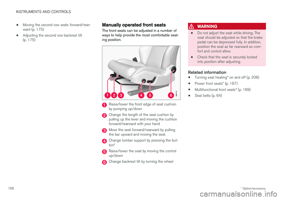
The front seats can be adjusted in a number of ways to help provide the most comfortable seat-ing position.
Raise/lower the front edge of seat cushion by pumping up/down
Change the length of the seat cushion by pulling up the lever and moving the cushionforward/rearward with your hand
Move the seat forward/rearward by pulling the bar upward and moving the seat.
Change lumbar support by pressing the but- ton *
Raise/lower the seat by moving the control up/down
Change backrest tilt by turning the wheel
WARNING
• Do not adjust the seat while driving. The seat should be adjusted so that the brakepedal can be depressed fully. In addition,position the seat as far rearward as com-fort and control allow.
• Check that the seat is securely lockedinto position after adjusting.
Related information
•
Turning seat heating
* on and off (p. 208)
• Power front seats
* (p. 167)
• Multifunctional front seats
* (p. 169)
• Seat belts (p. 64)
Page 177 of 580
INSTRUMENTS AND CONTROLS
}}
175
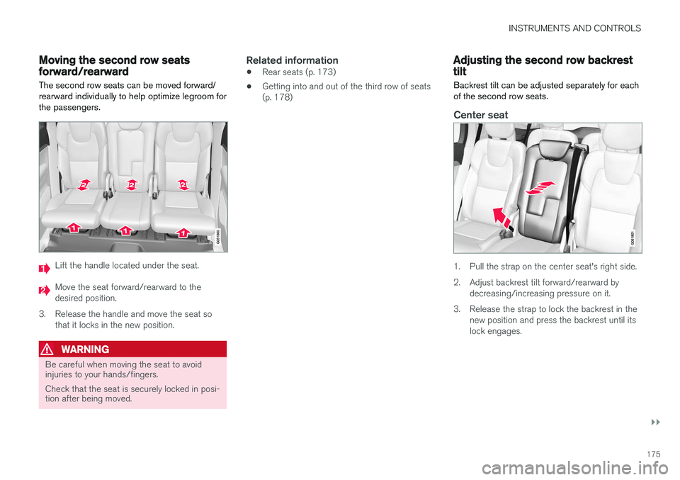
Moving the second row seats forward/rearward
The second row seats can be moved forward/ rearward individually to help optimize legroom forthe passengers.
Lift the handle located under the seat.
Move the seat forward/rearward to the desired position.
3. Release the handle and move the seat so that it locks in the new position.
WARNING
Be careful when moving the seat to avoid injuries to your hands/fingers. Check that the seat is securely locked in posi- tion after being moved.
Related information
• Rear seats (p. 173)
• Getting into and out of the third row of seats (p. 178)
Adjusting the second row backrest tilt
Backrest tilt can be adjusted separately for each of the second row seats.
Center seat
1. Pull the strap on the center seat's right side.
2. Adjust backrest tilt forward/rearward by decreasing/increasing pressure on it.
3. Release the strap to lock the backrest in the new position and press the backrest until its lock engages.
Page 178 of 580
||
INSTRUMENTS AND CONTROLS
* Option/accessory.
176
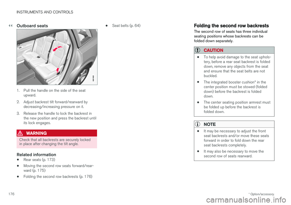
Outboard seats
1. Pull the handle on the side of the seat
upward.
2. Adjust backrest tilt forward/rearward by decreasing/increasing pressure on it.
3. Release the handle to lock the backrest in the new position and press the backrest until its lock engages.
WARNING
Check that all backrests are securely locked in place after changing the tilt angle.
Related information
• Rear seats (p. 173)
• Moving the second row seats forward/rear- ward (p. 175)
• Folding the second row backrests (p. 176) •
Seat belts (p. 64)
Folding the second row backrests
The second row of seats has three individual seating positions whose backrests can befolded down separately.
CAUTION
• To help avoid damage to the seat uphols- tery, before a rear seat backrest is foldeddown, remove any objects from the seatand ensure that the seat belts are notbuckled.
• The integrated booster cushion
* in the
center position must be stowed (foldeddown) before the backrest is foldeddown.
• The center seating position armrest mustbe folded up before the backrest isfolded down.
NOTE
•It may be necessary to adjust the front seat backrests and/or move these seatsforward in order to fold down the rearseat backrests completely.
• It may also be necessary to move thesecond row of seats rearward.