ECO mode VOLVO XC90 TWIN ENGINE 2018 Service Manual
[x] Cancel search | Manufacturer: VOLVO, Model Year: 2018, Model line: XC90 TWIN ENGINE, Model: VOLVO XC90 TWIN ENGINE 2018Pages: 686, PDF Size: 17 MB
Page 333 of 686

DRIVER SUPPORT
* Option/accessory.331
Camera
The camera is used by several driver support
systems to e.g. detect lane marker lines or road
signs. Note: This illustration is general and details may vary
depending on model.
The camera is used by the following functions:
• Adaptive Cruise Control*
• Pilot Assist*
• Lane Keeping Aid*
• Steering assistance at risk of collision
• City Safety
• Driver Alert Control*
• Road Sign Information*
• Active high beams*
Related information
•Camera limitations (p. 332)
• Recommended maintenance for the camera/
radar sensor (p. 335)
Page 366 of 686
DRIVER SUPPORT
364Selecting guidance to a rest area if
the Driver Alert Control warning has
been given
The Rest Stop Guidance function can be
switched on or off. When the guide is activated, it will automatically
display suggestions for a suitable place to take a
break if the DAC warning is given.
To select Rest Stop Guidance:
1. Tap Settings in the center display's Top
view.
2.
Select My Car IntelliSafe Driver Alert
Control .
3. Select/deselect Rest Stop Guidance to
activate/deactivate the function.
Related information
• Driver Alert Control (p. 362) Driver Alert Control limitations
Driver Alert Control (DAC) functionality may be
reduced in certain situations.
In certain situations, the system may provide a
warning even if it has not detected a change in
driving behavior, e.g.:
• in strong crosswinds
• on grooved road surfaces.
WARNING In certain cases, driving behavior might not be
affected despite the driver's fatigue – when
using the Pilot Assist function – resulting in
the driver not getting a warning from DAC.
It is therefore very important to always stop
and take a break at the slightest sign of fati-
gue, regardless of whether the DAC function
has issued a warning or not.
NOTE
The function uses the vehicle's camera unit,
which has some general limitations – see the
section "Camera unit limitations".
Related information
•
Driver Alert Control (p. 362) Lane Keeping Aid
Lane Keeping Aid (LKA 107
) is designed to
actively steer the vehicle on freeways, highways
and other major roads to help the driver reduce
the risk of the vehicle unintentionally veering out
of the lane.
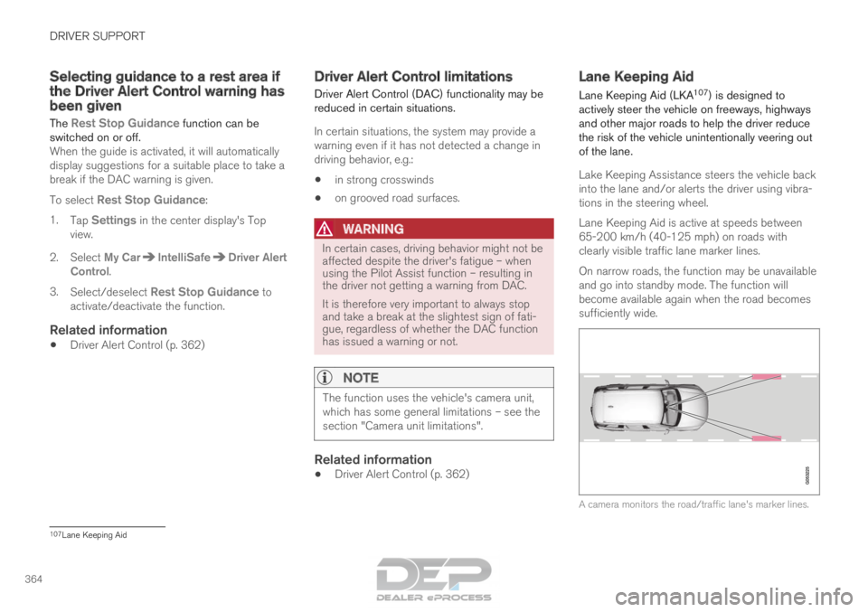
Lake Keeping Assistance steers the vehicle back
into the lane and/or alerts the driver using vibra-
tions in the steering wheel.
Lane Keeping Aid is active at speeds between
65-200 km/h (40-125 mph) on roads with
clearly visible traffic lane marker lines.
On narrow roads, the function may be unavailable
and go into standby mode. The function will
become available again when the road becomes
sufficiently wide. A camera monitors the road/traffic lane's marker lines.
107
Lane Keeping Aid
Page 369 of 686
DRIVER SUPPORT
}}
367
Activating/deactivating Lane
Keeping Aid
The Lane Keeping Aid (LKA
111
) function can be
switched On or Off.
On/OffPress the Lane Keeping Aid
button in the center display's
Function view. •
GREEN button indicator light - LKA is acti-
vated.
• GRAY button indicator light - LKA is deacti-
vated.
Related information
•Lane Keeping Aid (p. 364) Selecting type of assistance for
Lane Keeping Aid
The driver can determine what types of assis-
tance LKA 112
should provide if the vehicle veers
from its lane.
1. Select
Settings My Car IntelliSafe in
the center display's Top view.
2. Under Lane Keeping Aid Mode, select
what assistance LKA should provide:
• Assist the driver will receive steering
assistance but no warning.
• Both - the driver will receive both steering
assistance and a warning.
• Warning - the driver will only receive a
warning.
Related information
• Lane Keeping Aid (p. 364) Lane Keeping Aid limitations
In certain demanding driving conditions, Lane
Keeping Aid may not be able to properly assist
the driver. In these situations, it is recommended
that the function be deactivated. Examples of such situations include:
• road work
• winter driving conditions
• poor road surfaces
• a very sporty driving style
• bad weather with reduced visibility
• roads with indistinct or no lane markings
• sharp edges or lines other than the lane's
side markings
• when the power steering works at reduced
power - e.g. during cooling due to overheat-
ing (see section "Speed-dependent steering
force").
NOTE The function uses the vehicle's camera unit,
which has some general limitations – see the
section "Camera unit limitations".
111
Lane Keeping Aid
112 Lane Keeping Aid
Page 371 of 686
DRIVER SUPPORT
}}
369
Lane Keeping Aid symbols and
messages
A number of symbols and messages related to
Lane Keeping Aid LKA 113
may be displayed in
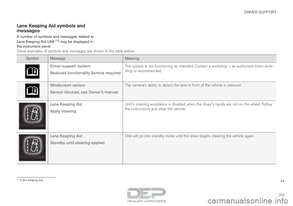
the instrument panel. Some examples of symbols and messages are shown in the table below. Symbol
Message MeaningDriver support system
Reduced functionality Service required
The system is not functioning as intended. Contact a workshop ‒ an authorized Volvo work-
shop is recommended. Windscreen sensor
Sensor blocked, see Owner's manual
The camera's ability to detect the lane in front of the vehicle is re\
duced.Lane Keeping Aid
Apply steering
LKA's steering assistance is disabled when the driver's hands are \
not on the wheel. Follow
the instructions and steer the vehicle.Lane Keeping Aid
Standby until steering applied
LKA will go into standby mode until the driver begins steering the vehic\
le again.113
Lane Keeping Aid
Page 388 of 686

DRIVER SUPPORT
* Option/accessory.
386 Park Assist Camera*
The Park Assist Camera can help provide the
driver when maneuvering in tight spaces by alert-
ing the driver to obstacles using the camera
screen and graphics in the center display.
The Park Assist Camera is a support function
that is automatically activated when reverse gear
is engaged. It can also be started manually from
the center display.
Example camera view
116
. Zoom
117
- zoom in/out 360° view* - activate/deactivate all cameras
PAS* - activate/deactivate Parking Assist
Lines - activate/deactivate trajectory lines Towbar
* - activate/deactivate trajectory lines
for towbar* 118 CTA
* - activate/deactivate Cross Traffic Alert
WARNING
•
The Parking Camera function is supple-
mentary driver support intended to facili-
tate driving and help make it safer – it
cannot handle all situations in all traffic,
weather and road conditions.
• The parking cameras have dead/blind
spots where objects cannot be detected.
• Pay particular attention to people and
animals near the vehicle.
• Objects/obstacles may be closer to the
vehicle than they appear on the screen.
• The parking cameras are not a substitute
for the driver's attention and judgment.
The driver is always responsible for
ensuring the vehicle is driven in a safe
manner, at the appropriate speed, with an
appropriate distance to other vehicles,
and in accordance with current traffic
rules and regulations.
Related information
•Park Assist Camera views (p. 387)
• Park Assist Camera trajectory lines (p. 388)
• Sensor field from Park Assist for Park Assist
Camera (p. 390)
• Starting the Park Assist Camera (p. 391)
• Park Assist Camera limitations (p. 391)
• Recommended maintenance of the Park
Assist Camera (p. 393)
• Recommended maintenance of the Park
Assist Camera (p. 393)
• Park Assist Camera symbols and messages
(p. 394) 116
The illustration is generic - details may vary according to vehicle mode\
l.
117 The trajectory lines will not be displayed when zooming in.
118 Not available in all markets.
Page 408 of 686
HYBRID INFORMATION
406General information about Twin
Engine
Twin Engine vehicles are driven just like any
other vehicle, but certain functions differ from a
vehicle powered exclusively by gasoline. The
electric motor powers the vehicle primarily at low
speeds; the gasoline engine is used at higher
speeds or during more active driving. The instrument panel displays Twin Engine-spe-
cific information - charging information, selected
drive mode, distance to discharged battery and
hybrid battery charge level.
Different drive modes can be selected while driv-
ing, e.g. electric power only or, if more power is
needed, a combination of electric and gasoline
power. The vehicle calculates the optimal combi-
nation of driveability, driving experience, environ-
mental impact and fuel economy for the selected
drive mode.
In order to function optimally, the hybrid battery
(and its electrical drive systems) and the gasoline
engine (and its drive systems) must be at the
correct operating temperature. Battery capacity
can be considerably reduced if the battery is too
cold or too hot. Preconditioning prepares the
vehicle's drive systems and passenger compart-
ment before driving to help reduce both wear and
energy consumption. It also helps increase the
hybrid battery's range.
The hybrid battery, which powers the electric
motor, is recharged using the charging cable. It
can also be recharged during light braking and through engine braking in gear position B. The
combustion engine can also help recharge the
hybrid battery.
Important
No electrical current
Keep in mind that if there is no electrical current
to the vehicle, i.e. the ignition is switched off or
the start battery is discharged, certain functions
such as brakes, power steering, etc. will not work.
WARNING If the vehicle does not have electrical current
and both the electric motor and the gasoline
engine are switched off, the brakes cannot be
used to stop the vehicle.
Towing not permitted
Never tow a Twin Engine vehicle behind another
vehicle, as this could damage the electric motor.
Exterior engine noise
WARNING
Keep in mind that the vehicle does not emit
any engine noise when using the electric
motor and may therefore be difficult to detect
for children, pedestrians, cyclists or animals.
This is especially true at low speeds, e.g. in
parking lots.
High-voltage electrical current
WARNING Several components in the vehicle work with
high voltage that can be hazardous in case of
an incorrect procedure. These components
and any orange wiring in the vehicle may only
be handled by trained and qualified Volvo
service technicians.
Do not touch anything that is not clearly descri-
bed in this Owner's Manual.
Related information
• Charging the hybrid battery (p. 407)
• Hybrid gauge (p. 87)
• Drive modes (p. 445)
• Starting and stopping preconditioning
(p. 231)
• Hybrid battery (p. 619)
• Factors affecting electric motor range
(p. 458)
• Gear selector positions for automatic trans-
missions (p. 439)
• Towing using a towline (p. 476)
Page 410 of 686
||HYBRID INFORMATION
408
released and the hybrid battery is recharged
at the same time.
• The combustion engine can also help
recharge the hybrid battery.
Related information
•Charge cable (p. 409)
• Charging current (p. 408)
• Opening and closing the charging socket
cover (p. 411)
• Initiating hybrid battery charging (p. 412)
• Stopping hybrid battery charging (p. 418)
• Charging status in the charging cable's
charging module (p. 415)
• Charging status in the vehicle's charging
socket (p. 414)
• Charging status in the instrument panel
(p. 416)
• Twin Engine symbols and messages in the
instrument panel (p. 419)
• Gear selector positions for automatic trans-
missions (p. 439)
• Changing drive mode (p. 449)
• Long-term storage of vehicles with hybrid
batteries (p. 421) Charging current
Charging current is used to charge the hybrid
battery and precondition the vehicle. Charging is
performed by connecting a charging cable
between the vehicle's charging socket and a
120/240 V electrical socket (alternating cur-
rent).
When the charging cable is activated, a message
will be displayed in the instrument panel and an
indicator light in the vehicle's charging socket will
illuminate. Charging current is primarily used for
battery charging, but is also used for precondi-
tioning. The vehicle's start battery is charged
along with the hybrid battery.
CAUTION
Never detach the charging cable from the
120/240 V outlet (AC, alternating current)
while charging is in progress – the
120/240 V outlet could be damaged in such
circumstances. Always interrupt charging first
and then disconnect the charging cable – first
from the vehicle's charging socket and then
from the 120/240 V outlet.
NOTE •
In extremely cold or hot weather, part of
the charging current is used to heat/cool
the hybrid battery and the passenger
compartment, resulting in a longer charg-
ing time.
• The charging time is longer if precondi-
tioning has been selected. The time
required depends primarily on the ambi-
ent temperature. There are normally several 120/240 V power
consumers in one fuse circuit, which means that
more than one power consumer (e.g. lighting,
vacuum cleaner, electric drill, etc.) may use the
same fuse.
Related information
•
Charge cable (p. 409)
• Charging status in the instrument panel
(p. 416)
• Charging status in the vehicle's charging
socket (p. 414)
• Starting and stopping preconditioning
(p. 231)
• Stopping hybrid battery charging (p. 418)
Page 427 of 686
STARTING AND DRIVING
}}
425
In some situations, such as in cold weather or if
the hybrid battery's charge level is too low, the
gasoline engine will start instead.
The vehicle should not be started with the charg-
ing cable connected. However, if the cable can-
not be pulled out or if the vehicle incorrectly
detects a cable that is not connected, the vehicle
can be started using an override procedure:
1.
Press the brake pedal and turn the start
knob clockwise.
2. Charge cable Remove before start will
appear in the instrument panel.
3.
Turn the start knob clockwise again.
4. Removed? Turn and hold start knob 7s
will appear. Turn the knob clockwise and hold
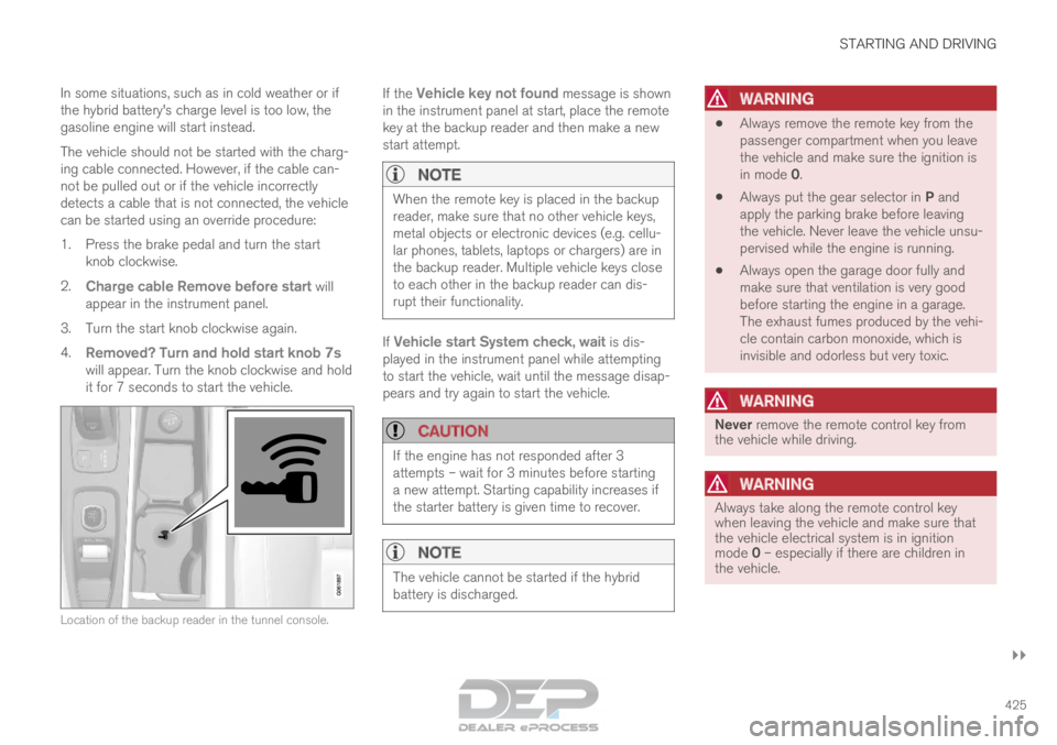
it for 7 seconds to start the vehicle. Location of the backup reader in the tunnel console. If the
Vehicle key not found message is shown
in the instrument panel at start, place the remote
key at the backup reader and then make a new
start attempt.
NOTE When the remote key is placed in the backup
reader, make sure that no other vehicle keys,
metal objects or electronic devices (e.g. cellu-
lar phones, tablets, laptops or chargers) are in
the backup reader. Multiple vehicle keys close
to each other in the backup reader can dis-
rupt their functionality.
If Vehicle start System check, wait is dis-
played in the instrument panel while attempting
to start the vehicle, wait until the message disap-
pears and try again to start the vehicle.
CAUTION If the engine has not responded after 3
attempts – wait for 3 minutes before starting
a new attempt. Starting capability increases if
the starter battery is given time to recover.
NOTE
The vehicle cannot be started if the hybrid
battery is discharged.
WARNING •
Always remove the remote key from the
passenger compartment when you leave
the vehicle and make sure the ignition is
in mode 0.
• Always put the gear selector in P and
apply the parking brake before leaving
the vehicle. Never leave the vehicle unsu-
pervised while the engine is running.
• Always open the garage door fully and
make sure that ventilation is very good
before starting the engine in a garage.
The exhaust fumes produced by the vehi-
cle contain carbon monoxide, which is
invisible and odorless but very toxic.
WARNING Never remove the remote control key from
the vehicle while driving.
WARNING
Always take along the remote control key
when leaving the vehicle and make sure that
the vehicle electrical system is in ignition
mode 0 – especially if there are children in
the vehicle.
Page 430 of 686
||STARTING AND DRIVING
428
Mode
Functions
II •The headlights illuminate.
• Warning/indicator lights illumi-
nate for 5 seconds.
• A number of other systems are
activated. However, seat and rear
window heating can only be acti-
vated when the engine is running.
This ignition mode uses a lot of
current from the battery and
should be avoided whenever pos-
sible! A
Also activated when the door is opened.
Related information
• Starting the vehicle (p. 424)
• Adjusting the steering wheel (p. 199)
• Jump starting using another battery (p. 469)
• Selecting ignition mode (p. 428) Selecting ignition mode
The vehicle's ignition can be put in various
modes (levels) to make different functions availa-
ble.
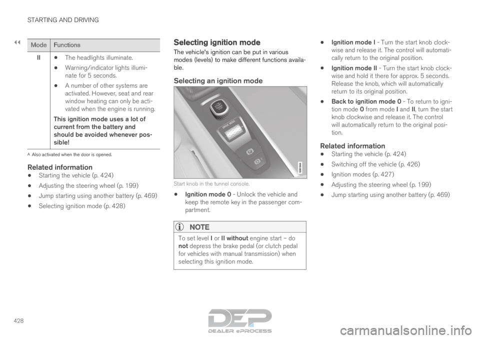
Selecting an ignition mode Start knob in the tunnel console.
•
Ignition mode 0 - Unlock the vehicle and
keep the remote key in the passenger com-
partment.
NOTE To set level I or II without engine start – do
not depress the brake pedal (or clutch pedal
for vehicles with manual transmission) when
selecting this ignition mode. •
Ignition mode I - Turn the start knob clock-
wise and release it. The control will automati-
cally return to the original position.
• Ignition mode II - Turn the start knob clock-
wise and hold it there for approx. 5 seconds.
Release the knob, which will automatically
return to its original position.
• Back to ignition mode 0 - To return to igni-
tion mode 0 from mode I and II, turn the start
knob clockwise and release it. The control
will automatically return to the original posi-
tion.
Related information
• Starting the vehicle (p. 424)
• Switching off the vehicle (p. 426)
• Ignition modes (p. 427)
• Adjusting the steering wheel (p. 199)
• Jump starting using another battery (p. 469)
Page 432 of 686

||STARTING AND DRIVING
430
augment braking. This is indicated in the instru-
ment panel with the pointer down in the red area.
Symbols in the instrument panel
Symbol
Meaning A
B
Check the brake fluid level. If the
level is low, fill brake fluid and
check to determine the reason for
the loss of brake fluid. A
B
Fault in pedal sensor. Symbol
Meaning A
B
Steady glow for 2 seconds after
the engine is started: Automatic
function check.
Steady glow for more than 2 sec-
onds: Fault in the ABS system. The
vehicle's regular brake system is
still working, but without the ABS
function. If the message Brake pedal Cha-
racteristics changed Service
required is displayed, the "Brake-
by-wire" system is not functioning
properly. The brake pedal will go
down further than normal and
greater pressure will be needed on
the pedal to achieve braking effect. A
Canadian models.
B US models.
WARNING •
If both symbols illuminate at the same
time and the brake level is below the MIN
mark in the reservoir or if a brake system-
related message is shown in the instru-
ment panel: DO NOT DRIVE. Have the
vehicle towed to a trained and qualified
Volvo service technician and have the
brake system inspected.
• If both symbols illuminate at the same
time and the brake level is normal (not
below the MIN mark in the reservoir) or if
a brake system-related message is
shown in the instrument panel: drive the
vehicle carefully to an authorized Volvo
workshop and have the brake system
inspected by a trained and qualified Volvo
service technician.
Related information
• Brake Assist System (p. 431)
• Auto-hold brakes (p. 436)
• Hill Start Assist (p. 437)
• Braking on wet roads (p. 431)
• Braking on salted roads (p. 431)
• Maintenance of the brake system (p. 432)
• Brake lights (p. 160)