sensor VOLVO XC90 TWIN ENGINE 2018 Owners Manual
[x] Cancel search | Manufacturer: VOLVO, Model Year: 2018, Model line: XC90 TWIN ENGINE, Model: VOLVO XC90 TWIN ENGINE 2018Pages: 686, PDF Size: 17 MB
Page 4 of 686
2
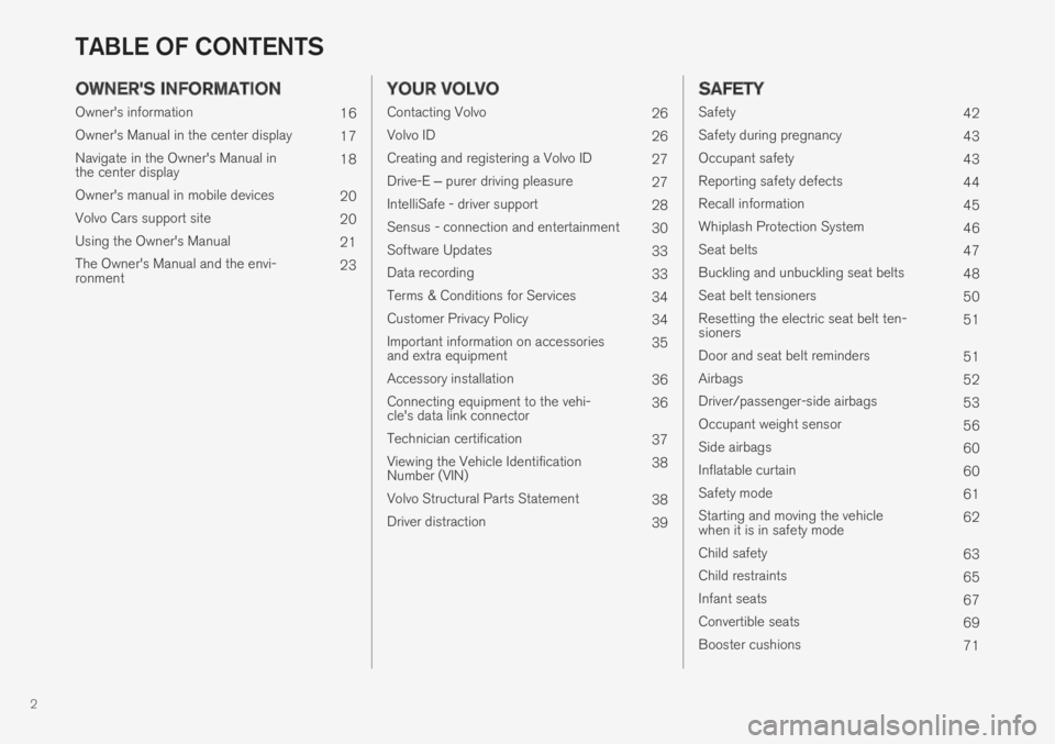
OWNER'S INFORMATION
Owner's information16
Owner's Manual in the center display17
Navigate in the Owner's Manual inthe center display18
Owner's manual in mobile devices20
Volvo Cars support site20
Using the Owner's Manual21
The Owner's Manual and the envi-ronment23
YOUR VOLVO
Contacting Volvo26
Volvo ID26
Creating and registering a Volvo ID27
Drive-E ‒ purer driving pleasure27
IntelliSafe - driver support28
Sensus - connection and entertainment30
Software Updates33
Data recording33
Terms & Conditions for Services34
Customer Privacy Policy34
Important information on accessoriesand extra equipment35
Accessory installation36
Connecting equipment to the vehi-cle's data link connector36
Technician certification37
Viewing the Vehicle IdentificationNumber (VIN)38
Volvo Structural Parts Statement38
Driver distraction39
SAFETY
Safety42
Safety during pregnancy43
Occupant safety43
Reporting safety defects44
Recall information45
Whiplash Protection System46
Seat belts47
Buckling and unbuckling seat belts48
Seat belt tensioners50
Resetting the electric seat belt ten-sioners51
Door and seat belt reminders51
Airbags52
Driver/passenger-side airbags53
Occupant weight sensor56
Side airbags60
Inflatable curtain60
Safety mode61
Starting and moving the vehiclewhen it is in safety mode62
Child safety63
Child restraints65
Infant seats67
Convertible seats69
Booster cushions71
TABLE OF CONTENTS
Page 5 of 686
3
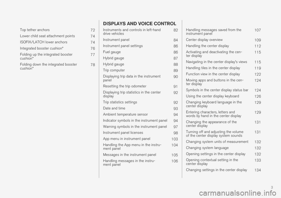
Top tether anchors72
Lower child seat attachment points74
ISOFIX/LATCH lower anchors74
Integrated booster cushion*76
Folding up the integrated boostercushion*77
Folding down the integrated boostercushion*78
DISPLAYS AND VOICE CONTROL
Instruments and controls in left-handdrive vehicles82
Instrument panel84
Instrument panel settings86
Fuel gauge86
Hybrid gauge87
Hybrid gauge88
Trip computer89
Displaying trip data in the instrumentpanel90
Resetting the trip odometer91
Displaying trip statistics in the centerdisplay92
Trip statistics settings92
Date and time93
Ambient temperature sensor94
Indicator symbols in the instrument panel94
Warning symbols in the instrument panel97
Instrument panel licenses98
App menu in instrument panel103
Handling the App menu in the instru-ment panel104
Messages in the instrument panel105
Handling messages in the instru-ment panel106
Handling messages saved from theinstrument panel107
Center display overview109
Handling the center display112
Activating and deactivating the cen-ter display115
Navigating in the center display's views115
Handling tiles in the center display119
Function view in the center display122
Moving apps and buttons in the cen-ter display124
Symbols in the center display status bar124
Using the center display keyboard126
Changing keyboard language in thecenter display129
Entering characters, letters andwords by hand in the center display129
Changing the appearance of thecenter display131
Turning off and adjusting the volumeof the center display system sounds131
Changing system units of measurement132
Changing system language132
Opening settings in the center display132
Opening contextual setting in thecenter display133
Changing settings in the center display134
Page 6 of 686
4
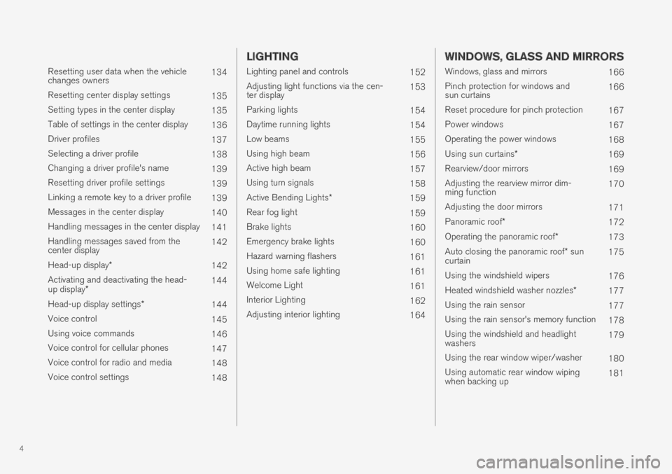
Resetting user data when the vehiclechanges owners134
Resetting center display settings135
Setting types in the center display135
Table of settings in the center display136
Driver profiles137
Selecting a driver profile138
Changing a driver profile's name139
Resetting driver profile settings139
Linking a remote key to a driver profile139
Messages in the center display140
Handling messages in the center display141
Handling messages saved from thecenter display142
Head-up display*142
Activating and deactivating the head-up display*144
Head-up display settings*144
Voice control145
Using voice commands146
Voice control for cellular phones147
Voice control for radio and media148
Voice control settings148
LIGHTING
Lighting panel and controls152
Adjusting light functions via the cen-ter display153
Parking lights154
Daytime running lights154
Low beams155
Using high beam156
Active high beam157
Using turn signals158
Active Bending Lights*159
Rear fog light159
Brake lights160
Emergency brake lights160
Hazard warning flashers161
Using home safe lighting161
Welcome Light161
Interior Lighting162
Adjusting interior lighting164
WINDOWS, GLASS AND MIRRORS
Windows, glass and mirrors166
Pinch protection for windows andsun curtains166
Reset procedure for pinch protection167
Power windows167
Operating the power windows168
Using sun curtains*169
Rearview/door mirrors169
Adjusting the rearview mirror dim-ming function170
Adjusting the door mirrors171
Panoramic roof*172
Operating the panoramic roof*173
Auto closing the panoramic roof* suncurtain175
Using the windshield wipers176
Heated windshield washer nozzles*177
Using the rain sensor177
Using the rain sensor's memory function178
Using the windshield and headlightwashers179
Using the rear window wiper/washer180
Using automatic rear window wipingwhen backing up181
Page 7 of 686
5
SEATS AND STEERING WHEEL
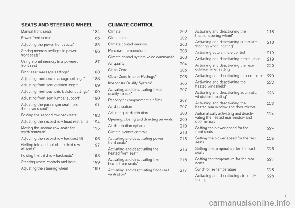
Manual front seats184
Power front seats*185
Adjusting the power front seats*185
Storing memory settings in powerfront seats*186
Using stored memory in a poweredfront seat187
Front seat massage settings*188
Adjusting front seat massage settings*188
Adjusting front seat cushion length189
Adjusting front seat side bolster settings*190
Adjusting front seat lumbar support*190
Adjusting the passenger seat fromthe driver's seat*191
Folding the second row backrests192
Adjusting the second row head restraints194
Moving the second row seats for-ward/rearward*195
Adjusting the second row backrest tilt196
Getting into and out of the third rowof seats*197
Folding the third row backrests* 198
Steering wheel controls and horn199
Adjusting the steering wheel199
CLIMATE CONTROL
Climate202
Climate zones202
Climate control sensors202
Perceived temperature203
Climate control system voice commands203
Air quality204
Clean Zone*205
Clean Zone Interior Package*206
Interior Air Quality System*206
Activating and deactivating the airquality sensor*207
Passenger compartment air filter207
Air distribution207
Adjusting air distribution208
Opening, closing and directing air vents209
Air distribution options210
Climate system controls213
Activating and deactivating powerfront seats*215
Activating and deactivating theheated front seat*216
Activating and deactivating theheated rear seats*216
Activating and deactivating front seatventilation*217
Activating and deactivating theheated steering wheel*218
Activating and deactivating automaticsteering wheel heating*218
Activating auto climate control219
Activating and deactivating recirculation219
Activating and deactivating the recir-culation timer setting220
Activating and deactivating max defroster220
Activating and deactivating theheated windshield*222
Activating and deactivating automaticwindshield heating*223
Activating and deactivating theheated rear window and door mirrors223
Automatically activating and deacti-vating the heated rear window anddoor mirrors
224
Setting the blower speed for thefront seats224
Setting the blower speed for the rearseats225
Setting the temperature for the frontseats226
Setting the temperature for the rearseats227
Synchronize temperature228
Activating and deactivating air condi-tioning228
Page 10 of 686
8
Pilot Assist limitations323
Pilot Assist* symbols and messages324
Radar sensor326
Radar sensor limitations327
Recommended maintenance for theradar sensor330
Radar sensor type approval330
Camera331
Camera limitations332
Recommended maintenance for thecamera/radar sensor335
City Safety™335
City Safety parameters and sub-functions336
Setting a warning distance for City Safety338
Detecting obstacles with City Safety339
City Safety in crossing traffic341
Limitations of City Safety in crossingtraffic342
City Safety and delayed evasivemaneuvers343
City Safety limitations344
City Safety messages346
Rear Collision Warning347
Rear Collision Warning limitations347
BLIS*348
Activating/deactivating BLIS349
BLIS limitations350
Recommended maintenance for BLIS351
BLIS messages352
Cross Traffic Alert*353
Activating/deactivating Cross TrafficAlert354
Cross Traffic Alert limitations354
Recommended maintenance forCross Traffic Alert355
Cross Traffic Alert messages356
Road Sign Information*357
Activating/deactivating Road SignInformation358
Road Sign Information and sign displays358
Road Sign Information and SensusNavigation359
Road Sign Information with SpeedWarning and Settings359
Activating/deactivating Speed Warn-ing in Road Sign Information360
Road Sign Information with speedcamera information361
Road Sign Information limitations361
Driver Alert Control362
Activating/deactivating Driver AlertControl363
Selecting guidance to a rest area ifthe Driver Alert Control warning hasbeen given
364
Driver Alert Control limitations364
Lane Keeping Aid364
Steering assistance with Lane Keep-ing Aid366
Activating/deactivating Lane Keeping Aid367
Selecting type of assistance for LaneKeeping Aid367
Lane Keeping Aid limitations367
Lane Keeping Aid symbols and mes-sages369
Lane Keeping Aid symbols in theinstrument panel371
Steering assistance at risk of collision372
Activating/deactivating steeringassistance during collision risks372
Run-Off Mitigation with steeringassistance373
Run-Off Mitigation with steeringassistance levels373
Activating/deactivating Run-Off Miti-gation with steering assistance374
Limitations of Run-Off Mitigationwith steering assistance374
Steering assistance during collisionrisks from oncoming traffic375
Page 11 of 686
9
Activating/deactivating Steeringassistance during collision risks withoncoming vehicles
376
Limitations of steering assistanceduring collision risks from oncomingtraffic
376
Steering assistance during collisionrisks from behind*377
Activating/deactivating Steeringassistance during collision risks frombehind*
378
Limitations of steering assistanceduring collision risks from behind378
Symbols and messages for steeringassistance during collision risks380
Park Assist*381
Park Assist front, rear and sides382
Activating/deactivating Park Assist383
Park Assist limitations383
Recommended maintenance forPark Assist384
Park Assist symbols and messages385
Park Assist Camera*386
Park Assist Camera views387
Park Assist Camera trajectory lines388
Sensor field from Park Assist forPark Assist Camera390
Starting the Park Assist Camera391
Park Assist Camera limitations391
Recommended maintenance of thePark Assist Camera393
Park Assist Camera symbols andmessages394
Park Assist Pilot* 395
Types of parking with Park Assist Pilot395
Parking with Park Assist Pilot 396
Leaving a parking space with ParkAssist Pilot399
Park Assist Pilot* limitations 400
Recommended maintenance forPark Assist Pilot402
Park Assist Pilot* messages403
HYBRID INFORMATION
General information about Twin Engine406
Charging the hybrid battery407
Charging current408
Charge cable409
Charging cable residual current device410
Charging cable temperature monitoring411
Opening and closing the chargingsocket cover411
Initiating hybrid battery charging412
Charging status in the vehicle'scharging socket414
Charging status in the chargingcable's charging module415
Charging status in the instrument panel416
Stopping hybrid battery charging418
Twin Engine symbols and messagesin the instrument panel419
Long-term storage of vehicles withhybrid batteries421
Page 40 of 686
YOUR VOLVO
38
Viewing the Vehicle IdentificationNumber (VIN)
When contacting a Volvo retailer, about e.g. yourVolvo On Call subscription, your Vehicle Identifi-
cation Number (VIN5) may be needed.1.Tap Settings in the Top view in the centerdisplay.
2.Proceed to SystemSystem Information
Vehicle Identification Number.
> The vehicle identification number will bedisplayed.
Volvo Structural Parts Statement
Volvo is one of the leading companies for carsafety.
Volvo engineers and manufactures vehiclesdesigned to help protect vehicle occupants in theevent of a collision.
Volvos are designed to absorb the impact of acollision. This energy absorption system including,but not limited to, structural components such asbumper reinforcement bars, bumper energyabsorbers, frames, rails, fender aprons, A-pillars,B-pillars and body panels must work together tomaintain cabin integrity and protect the vehicleoccupants.
The supplemental restraint system including butnot limited to air bags, side curtain air bags, anddeployment sensors work together with theabove components to provide proper timing forair bag deployment.
Due to the above, Volvo Car USA does not sup-port the use of aftermarket, alternative or any-thing other than original Volvo parts for collisionrepair.
Volvo Car USA also recommends using Volvo-approved replacement glass. The use of after-market glass, particularly a windshield, can havean adverse effect on collision avoidance andadvanced lighting systems.
In addition Volvo does not support the use or re-use of structural components from an existingvehicle that has been previously damaged.Although these parts may appear equivalent, it isdifficult to tell if the parts have been previouslyreplaced with non-OE parts or if the part hasbeen damaged as a result of a prior collision. Thequality of these used parts may also have beenaffected due to environmental exposure.
Related information
•Data recording (p. 33)
5Vehicle Identification Number
Page 44 of 686
SAFETY
42
Safety
The vehicle is equipped with a number of safetysystems that work together to help protect thevehicle's driver and passengers in the event ofan accident.
The vehicle is equipped with a number of sensorsthat may react in the event of an accident andactivate different safety systems, such as the air-bag system and seat belt tensioners. Dependingon the specific conditions of the accident, e.g.collisions at certain angles, overturning or swerv-ing, the systems react differently to help providethe best protection.
There are also mechanical safety systems suchas the Whiplash Protection System. The vehicleis also built so that a large part of the force of acollision is distributed to the vehicle's members,pillars, floor, roof and other parts of the body.
After an accident, the vehicle's safety mode maybe activated if any important function in the vehi-cle has been damaged.
Warning symbol in the instrument panel
The warning symbol in the instrumentpanel illuminates when the vehicle'selectrical system is in ignition mode II.The symbol will go out after approx. 6seconds if no faults are detected in the vehicle'ssafety systems.
WARNING
If the warning symbol remains illuminated orswitches on while driving and the messageSRS airbag Service urgent Drive toworkshop is displayed in the instrumentpanel, this indicates that something in thesafety system is not functioning properly.Volvo recommends contacting an authorizedVolvo workshop for repairs as soon as possi-ble.
WARNING
Never attempt to alter or repair any of thevehicle's safety systems yourself. Incorrectlyperformed repairs to any system could impairfunction and lead to serious injury. Volvo rec-ommends contacting an authorized Volvoworkshop.
If this dedicated warning symbol is notfunctioning, the general warning sym-bol will illuminate instead and the samemessage will be displayed in the instru-ment panel.
Related information
•Safety during pregnancy (p. 43)
•Occupant safety (p. 43)
•Reporting safety defects (p. 44)
•Recall information (p. 45)
•Seat belts (p. 47)
•Airbags (p. 52)
•Whiplash Protection System (p. 46)
•Safety mode (p. 61)
•Child safety (p. 63)
Page 55 of 686
SAFETY
}}
53
WARNING
If your vehicle has become water-damaged inany way (e.g., soaked floor mats/standingwater on the floor of the vehicle), do notattempt to start the engine. This may causeairbag deployment, which could result in seri-ous injury. Volvo recommends towing thevehicle directly to an authorized Volvo work-shop.
Before attempting to tow the vehicle:
1.Switch off the ignition for at least 10minutes and disconnect the battery.
2. Follow the instructions for manually over-riding the shiftlock system.
Deployed airbags
WARNING
If any of the airbags have deployed:
•Do not attempt to drive the vehicle. Haveit towed to an authorized workshop.
•If necessary, seek medical attention.
Related information
•Safety (p. 42)
•Driver/passenger-side airbags (p. 53)
•Side airbags (p. 60)
•Inflatable curtain (p. 60)
Driver/passenger-side airbags
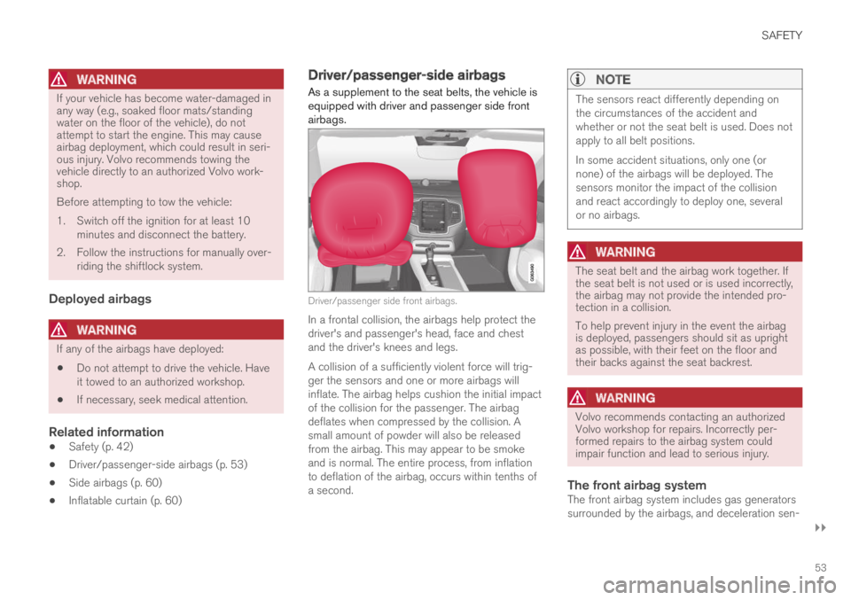
As a supplement to the seat belts, the vehicle isequipped with driver and passenger side frontairbags.
Driver/passenger side front airbags.
In a frontal collision, the airbags help protect thedriver's and passenger's head, face and chestand the driver's knees and legs.
A collision of a sufficiently violent force will trig-ger the sensors and one or more airbags willinflate. The airbag helps cushion the initial impactof the collision for the passenger. The airbagdeflates when compressed by the collision. Asmall amount of powder will also be releasedfrom the airbag. This may appear to be smokeand is normal. The entire process, from inflationto deflation of the airbag, occurs within tenths ofa second.
NOTE
The sensors react differently depending onthe circumstances of the accident andwhether or not the seat belt is used. Does notapply to all belt positions.
In some accident situations, only one (ornone) of the airbags will be deployed. Thesensors monitor the impact of the collisionand react accordingly to deploy one, severalor no airbags.
WARNING
The seat belt and the airbag work together. Ifthe seat belt is not used or is used incorrectly,the airbag may not provide the intended pro-tection in a collision.
To help prevent injury in the event the airbagis deployed, passengers should sit as uprightas possible, with their feet on the floor andtheir backs against the seat backrest.
WARNING
Volvo recommends contacting an authorizedVolvo workshop for repairs. Incorrectly per-formed repairs to the airbag system couldimpair function and lead to serious injury.
The front airbag system
The front airbag system includes gas generatorssurrounded by the airbags, and deceleration sen-
Page 56 of 686

||
SAFETY
54
sors that activate the gas generators, causing theairbags to be inflated with nitrogen gas.
As the movement of the seats' occupants com-presses the airbags, some of the gas is expelledat a controlled rate to provide better cushioning.Both seat belt tensioners also deploy, minimizingseat belt slack. The entire process, from inflationto deflation of the airbag, occurs within tenths ofa second.
The location of the front airbags is indicated bySRS AIRBAG embossed on the steering wheelpad and above the glove compartment, and bydecals on both sun visors and on the front andfar right side of the dash.
The driver's side front airbag is folded andlocated in the steering wheel hub.
The knee airbag is folded on the underside ofthe dashboard on the driver's side. The textAIRBAG is embossed on the panel.
The passenger's side front airbag is foldedbehind a panel located above the glove compart-ment.
WARNING
•The airbags in the vehicle are designed tobe a SUPPLEMENT to-not a replacementfor-the three-point seat belts. For maxi-mum protection, wear seat belts at alltimes. Be aware that no system can pre-vent all possible injuries that may occur inan accident.
•Never drive with your hands on the steer-ing wheel pad/airbag housing.
•The front airbags are designed to helpprevent serious injury. Deployment occursvery quickly and with considerable force.During normal deployment and depend-ing on variables such as seating position,one may experience abrasions, bruises,swellings, or other injuries as a result ofdeployment of one or both of the airbags.
•When installing any accessory equipment,make sure that the front airbag system isnot damaged. Any interference in the sys-tem could cause malfunction.
Front airbag deployment
•The front airbags are designed to deploy dur-ing certain frontal or front-angular collisions,impacts, or decelerations, depending on thecrash severity, angle, speed and objectimpacted. The airbags may also deploy in
certain non-frontal collisions where rapiddeceleration occurs.
•The airbag system sensors, which trigger thefront airbags, are designed to react to boththe impact of the collision and the inertialforces generated by it, and to determine ifthe intensity of the collision is sufficient forthe seat belt tensioners and/or airbags to bedeployed.
However, not all frontal collisions activate thefront airbags.
•If the collision involves a nonrigid object (e.g.,a snow drift or bush), or a rigid, fixed objectat a low speed, the front airbags will not nec-essarily deploy.
•Front airbags do not normally deploy in aside impact collision, in a collision from therear or in a rollover situation.
•The amount of damage to the bodyworkdoes not reliably indicate if the airbagsshould have deployed or not.