VOLVO XC90 TWIN ENGINE 2019 Owners Manual
Manufacturer: VOLVO, Model Year: 2019, Model line: XC90 TWIN ENGINE, Model: VOLVO XC90 TWIN ENGINE 2019Pages: 697, PDF Size: 10.33 MB
Page 401 of 697

DRIVER SUPPORT
}}
399
Park Assist Camera trajectory lines
The Park Assist Camera uses trajectory lines
and fields on the screen to indicate the vehicle's
position in relation to its immediate surround-
ings. Example
119
of trajectory lines.
The trajectory lines show the anticipated trajec-
tory for the vehicle's outermost dimensions based
on the current position of the steering wheel to help simplify parallel parking, backing into tight
spaces or attaching a trailer.
The lines on the screen are projected as if they
were painted lines on the ground behind the
vehicle and are directly affected by the way in
which the steering wheel is turned. This enables
the driver to see path the vehicle will take, even if
he/she turns the steering wheel.
These lines also indicate the outermost limits that
any object (towbar, rearview mirrors, corners of
the body, etc.) extends out from the vehicle.
NOTE
When reversing with a trailer that is not
electrically connected to the vehicle, the
screen guide lines show the path the
vehicle will take – not the trailer.
The screen does not show guide lines
when a trailer is electrically connected to
the vehicle's electrical system.
Guide lines are not shown when zooming
in.
CAUTION
Bear in mind that when the rearward
camera view is selected, the screen only
shows the area behind the vehicle – pay
attention to the sides and front of the
vehicle when steering while reversing.
The same applies to the reverse – pay
attention to what is happening with the
rear parts of the vehicle when the front
camera view is selected.
Note that the guide lines show the short-
est path – pay extra attention to ensure
that the vehicle sides do not come in
contact with/travel over anything when
steering while driving forward or that the
vehicle front moves toward/over anything
when steering while reversing. 119
The illustration is generic - details may vary according to vehicle mode\
l.
Page 402 of 697

||DRIVER SUPPORT
* Option/accessory.
400
Trajectory lines in 360° view* 360° view with trajectory lines
119
.
In the 360° view, trajectory lines are shown
behind, in front of, or to the sides of the vehicle,
depending on the direction of travel.
When driving forward: Front lines
When backing up: Side lines and rear lines.
When the front or rear camera is selected, the
trajectory lines will be shown regardless of the
vehicle's direction of travel.
With a side camera selected, the trajectory lines
will only be shown if the vehicle is backing up.Trajectory lines for a towbar* Towbar with trajectory line
119
. Towbar
- activate trajectory lines for towbar.
Zoom
- zoom in/out.The camera can help make hitching a trailer eas-
ier by showing an anticipated trajectory line for
the towbar's path toward the trailer.
1.
Tap Towbar (1).
>
The trajectory line for the towbar's antici-
pated path toward the vehicle will appear
and the vehicle's trajectory lines will dis-
appear.
Trajectory lines cannot be displayed for
both the vehicle and the towbar at the
same time.
2. Tap Zoom (2) for a close-up view for more
precise maneuvering.
>
The camera will zoom in.
Related information
Park Assist Camera* (p. 396) 119
The illustration is generic - details may vary according to vehicle mode\
l.
Page 403 of 697

DRIVER SUPPORT
}}
401
Sensor field from Park Assist for
Park Assist Camera
If the vehicle is equipped with Park Assist, dis-
tances will be shown in the 360° view with col-
ored fields for each sensor that has detected an
obstacle.
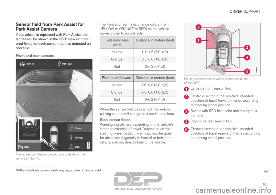
Front and rear sensors The screen can display colored sensor fields on the
vehicle symbol
120
. The front and rear fields change colors (from
YELLOW to ORANGE to RED) as the vehicle
moves closer to an obstacle. Field color rear-
ward Distance in meters (feet)
Yellow
0.6-1.5 (2.0-4.9)
Orange 0,3–0,6 (1,0–2,0)
Red 0-0.3 (0-1.0) Field color forward
Distance in meters (feet)
Yellow
0,6–0,8 (2,0–2,6)
Orange 0,3–0,6 (1,0–2,0)
Red 0-0.3 (0-1.0) When the sensor field color is red, the audible
pulsing sounds will change to a continuous tone.
Side sensor fields
Warning signals vary depending on the vehicle's
intended direction of travel. Depending on the
steering wheel position, warnings may be given
for obstacles diagonally in front of or behind the
vehicle, not only directly behind the vehicle. Parking sensor sectors where obstacles can be
detected
120
. Left-side front sensor field
Obstacle sector in the vehicle's intended
direction of travel forward – varies according
to steering wheel position
Sector with RED field color and rapidly puls-
ing tone
Right-side rear sensor field
Obstacle sector in the vehicle's intended
direction of travel rearward – varies according
to steering wheel position.
120
The illustration is generic - details may vary according to vehicle mode\
l.
Page 404 of 697

||DRIVER SUPPORT
* Option/accessory.
402 The color of the side field changes as the vehicle
moves closer to the object – from YELLOW to
RED.
Side field color
Distance in meters (feet)
Yellow
0,25–0,9 (0,8–3,0)
Red 0–0,25 (0–0,8)When the sensor field is RED, the audible pulsing
signal will become more rapid.
Related information
Park Assist Camera* (p. 396) Starting the Park Assist Camera
The Park Assist Camera starts automatically
when reverse gear is engaged or can be started
manually using one of the center display's func-
tion buttons.
Camera view when backing upWhen reverse gear is engaged, the screen shows
the rear view 121
.
Camera view when manually starting
the camera
Start the Park Assist Camera
using this button in the center
display's Function view.
The screen will first show the
most recently used camera
view. However, each time the
engine is started, the previous side view will be
replaced by the 360° view and a previously dis-
played zoomed-in rear view will be replaced by
the regular rear view.
Automatically deactivating the cameraFront view switches off when the vehicle's speed
reaches 25 km/h (16 mph) to help avoid dis-
tracting the driver. It will be automatically reactiva-
ted if the vehicle's speed falls below 22 km/h
(14 mph) within 1 minute as long as the vehicle's
speed has not exceeded 50 km/h (31 mph). Other camera views switch off at 15 km/h
(9 mph) and are not reactivated.
Related information
Park Assist Camera* (p. 396) 121
In Canada, it is also possible to select the 360° view.
Page 405 of 697

DRIVER SUPPORT
}}
403
Park Assist Camera limitations
The Park Assist Camera may not be able to
detect all conditions in all situations and func-
tionality may therefore be limited.
The driver should be aware of the following limi-
tations for the Park Assist Camera:
WARNING Be extra cautious when
reversing if this symbol is
shown when a trailer, bike
carrier or similar is attached
and electrically connected
to the vehicle.
The symbol indicates that
the rear parking assist sensors are deacti-
vated and will not warn of any obstacles.
NOTE A bike carrier and other accessories mounted
on the rear of the vehicle can obscure the
camera's view.
Blind sectors There are "blind" sectors between the cameras' fields of
vision.
With 360° view selected, objects/obstacles may
not be detected if they are located in the "joints"
where the edges of the individual camera views
meet.
WARNING
Even if it seems as though only a fairly small
section of the screen image is obstructed, this
may mean that a relatively large sector is hid-
den and obstacles there may not be detected
until they are very near the vehicle.
Defective cameraIf a camera sector is dark and
contains this symbol, this indi-
cates that the camera is not
functioning properly.
See the following illustration for
an example. The vehicle's left-side camera is malfunctioning.
Dark camera sector
A dark camera sector may also be displayed in
the following situations, but without the defective
camera symbol:
a door is open
the tailgate is open
a rearview mirror is folded in
Lighting conditionsThe camera image is automatically adjusted
according to the current lighting conditions. This
Page 406 of 697

||DRIVER SUPPORT
* Option/accessory.
404 means that the brightness and quality of the
image may vary slightly. Poor lighting conditions
may result in reduced image quality.
Related information
Park Assist Camera* (p. 396) Recommended maintenance of the
Park Assist Camera
Each of the Park Assist Cameras, located above
the license plate, the grille and in both door mir-
rors, require a certain degree of maintenance.
Clean the camera lenses regularly using luke-
warm water and car washing detergent. Wash
gently to avoid scratching the lens.
NOTE Keep the camera lens free of dirt, snow and
ice to help ensure the best functionality. This
is particularly important in poor light condi-
tions.
Related information
Park Assist Camera* (p. 396)
Page 407 of 697

DRIVER SUPPORT
* Option/accessory.405
Park Assist Camera symbols and
messages
Symbols and messages for the Park Assist
Camera may be displayed in the instrument
panel and/or the center display.
Some examples of symbols and messages are shown in the table below. Symbol
Message Meaning The rear Park Assist sensors are turned off and no acoustic warnings or field markings for obsta-
cles/objects will be provided.
The camera is not functioning properly.
Park Assist System
Sensors blocked, cleaning
needed One or more of the sensors are blocked. Check and clean/remove the obsta\
cle as soon as possible.
Park Assist System
Unavailable Service required The system is not functioning as intended. Contact a workshop ‒ an authorized Volvo workshop is
recommended. A text message can be erased by briefly pressing
the
button in the center of the right-side
steering wheel keypad. If the message persists: Contact a workshop ‒ an
authorized Volvo workshop is recommended.
Related information
Park Assist Camera* (p. 396)
Page 408 of 697

DRIVER SUPPORT
* Option/accessory.
406 Park Assist Pilot*
Park Assist Pilot (
PAP 122
) helps the driver pull
into and out of parking spaces.
PAP first checks whether there
is sufficient space and then
steers the car into the space.
The center display uses sym-
bols, graphics and messages to
inform the driver of what steps
need to be taken and when.
WARNING
The PAP function is supplementary driver
support intended to facilitate driving and
help make it safer – it cannot handle all
situations in all traffic, weather and road
conditions.
Pay particular attention to people and
animals near the vehicle.
PAP is not a substitute for the driver's
attention and judgment. The driver is
always responsible for ensuring the vehi-
cle is driven in a safe manner, at the
appropriate speed, with an appropriate
distance to other vehicles, and in accord-
ance with current traffic rules and regula-
tions.
NOTE The PAP function measures the space and
steers the vehicle – the driver's role is to:
keep close watch of the area around the
vehicle
follow the instructions on the center dis-
play
change gears (reverse/forward) – a
"ping" sound indicates when the driver
should change gears
regulate and maintain a safe speed
apply the brakes and stop.
Related information
Types of parking with Park Assist Pilot
(p. 406)
Parking with Park Assist Pilot (p. 408)
Leaving a parking space with Park Assist
Pilot (p. 410)
Park Assist Pilot* limitations (p. 411)
Recommended maintenance for Park Assist
Pilot (p. 413)
Park Assist Pilot* messages (p. 414) Types of parking with Park Assist
Pilot
Park Assist Pilot (PAP 123
) can be used for the
following types of parking. 122
Park Assist Pilot
123 Park Assist Pilot
Page 409 of 697

DRIVER SUPPORT
* Option/accessory.407
Parallel parkingOverview of parallel parking.
The PAP function helps park the vehicle using
the following steps:
1.
The system searches for and measures
potential parking spaces.
2. The vehicle is steered while it is backing into the parking space.
3. The vehicle's position in the space is adjusted by driving forward/backward.
The Park Out function can be used to receive
assistance from PAP while pulling out of a park-
ing space. See the section “Leaving a parking
space with Park Assist Pilot”.
Perpendicular parking Perpendicular parking overview.
The PAP function helps the vehicle using the fol- lowing steps:
1.
The system searches for and measures
potential parking spaces.
2. The vehicle is steered while it is backing into the space and its position is adjusted by driv-
ing forward/backward.
NOTE The PAP function
Park Out cannot help the
vehicle leave a perpendicular parking space –
the function should only be used for parallel
parking.
Related information
Park Assist Pilot* (p. 406)
Leaving a parking space with Park Assist
Pilot (p. 410)
Page 410 of 697

DRIVER SUPPORT
408Parking with Park Assist Pilot
Park Assist Pilot (PAP 124
) helps the driver park
using three different steps. The function can also
help the driver pull out of a parking space.
NOTE The PAP function measures the space and
steers the vehicle – the driver's role is to:
keep close watch of the area around the
vehicle
follow the instructions on the center dis-
play
change gears (reverse/forward) – a
"ping" sound indicates when the driver
should change gears
regulate and maintain a safe speed
apply the brakes and stop. Information about the actions required by the
driver are provided in the center display using
symbols, graphics and/or text.
PAP can be activated if the following criteria have
been met after the engine is started:
No trailer is hitched to the vehicle
Your vehicle's speed is lower than 30 km/h
(20 mph).
NOTE The distance between the vehicle and parking
spots should be 0.5-1.5 meters (1.6-5.0 ft)
when PAP is looking for parking.
ParkingPAP parks the vehicle using the following steps:
1. The system searches for and measures
potential parking spaces.
2. The vehicle is steered while it is backing into the parking space.
3. The vehicle is positioned in the parking space (the driver may be prompted to shift
gears).
Searching for and measuring potential
parking spots
The function can be activated
in the center display's Function
view.
It can also be accessed from
the camera views. Parallel parking overview.
Perpendicular parking overview.
To do so: 124
Park Assist Pilot