VOLVO XC90 TWIN ENGINE 2020 Owners Manual
Manufacturer: VOLVO, Model Year: 2020, Model line: XC90 TWIN ENGINE, Model: VOLVO XC90 TWIN ENGINE 2020Pages: 693, PDF Size: 13.34 MB
Page 461 of 693

STARTING AND DRIVING
}}
459
Battery drain
The electrical functions in the vehicle drain the battery to varying degrees. Avoid usingignition mode II when the engine is switched
off. Use ignition mode I instead, as this uses
less electrical current.
Note that certain accessories may also drain power from the electrical system. Do not usefunctions that use a lot of electrical currentwhen the engine is turned off. Examples ofsuch functions are: blower
headlights
windshield wipers
audio system (especially at high volume).
If the starter battery voltage is low, a message is shown in the driver display. The vehicle'senergy-saving function will then turn off orreduce certain functions, such as the blowerand/or the audio system.
–Charge the battery by starting the engine and let it run for at least 15 minutes (driv-ing charges the battery faster than lettingthe engine idle).
Related information
Start battery (p. 613)
Ignition modes (p. 415)
Jump starting using another battery If the start battery is discharged, current from another battery can be used to start the vehi-cle.
Jumper cable connecting points.
CAUTION
The charging point of the vehicle is only intended for jump starting the vehicle inquestion. The charging point is notintended for jump-starting another vehicle.Using the charging point to start anothervehicle could cause a fuse to blow, whichwould cause the charging point to stopworking.
If a fuse has blown, 12 V Battery Fuse failure
Service required will be displayed in the instrument panel. Volvo recommends contact- ing an authorized Volvo workshop. To avoid short circuits or other damage, the following steps are recommended when jumpstarting the battery:
Page 462 of 693
||
STARTING AND DRIVING
4601. Put the ignition in mode
0.
2. Make sure the auxiliary battery (the bat- tery used to jump start the discharged battery) has a voltage of 12 volts.
3. If the auxiliary battery is in another vehicle, turn off that vehicle's engine and makesure that the vehicles are not touchingeach other.
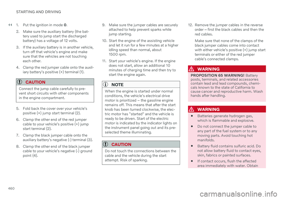
4. Clamp the red jumper cable onto the auxil- iary battery's positive (+) terminal (1).
CAUTION
Connect the jump cable carefully to pre- vent short circuits with other componentsin the engine compartment.
5. Fold back the cover over your vehicle's positive (+) jump start terminal (2).
6. Clamp the other end of the red jumper cable to your vehicle's positive (+) jump start terminal (2).
7. Clamp the black jumper cable onto the auxiliary battery's negative (-) terminal (3).
8. Clamp the other end of the black jumper cable to your vehicle's negative (-) groundpoint (4). 9. Make sure the jumper cables are securely
attached to help prevent sparks whilejump starting.
10. Start the engine of the assisting vehicle and let it run for a few minutes at a higheridling speed than normal, about1500 rpm.
11. Start your vehicle's engine. If the engine does not start, allow an additional 10minutes of charging time and then try tostart the engine again.
NOTE
When the engine is started under normal conditions, the vehicle's electrical drivemotor is prioritized – the gasoline engineremains off. This means that after the startknob has been turned clockwise, the elec-tric motor has "started" and the vehicle isready to be driven. Start of the electricmotor is indicated by the indicator lights onthe instrument panel going out and its pre-selected theme illuminating.
CAUTION
Do not touch the connections between the cable and the vehicle during the startattempt. Risk of sparking.
12. Remove the jumper cables in the reverseorder ‒ first the black cables and then the
red cables. Make sure that none of the clamps of the black jumper cables come into contactwith either vehicle's positive (+) jump startterminals or either of the red jumpercable's connected clamps.
WARNING
PROPOSITION 65 WARNING! Battery
posts, terminals, and related accessories contain lead and lead compounds, chemi-cals known to the state of California tocause cancer and reproductive harm. Washhands after handling.
WARNING
Batteries generate hydrogen gas, which is flammable and explosive.
Do not connect the jumper cable toany part of the fuel system or to anymoving parts. Avoid touching hotmanifolds.
Battery fluid contains sulfuric acid. Donot allow battery fluid to contact eyes,skin, fabrics or painted surfaces.
If contact occurs, flush the affectedarea immediately with water. Obtain
Page 463 of 693

STARTING AND DRIVING
}}
* Option/accessory.461
medical help immediately if eyes are affected.
Never expose the battery to open flameor electric spark. Do not smoke nearthe battery. Failure to follow theinstructions for jump starting can leadto injury.
NOTE
The vehicle cannot be started if the hybrid battery is discharged.
Related information
Starting the vehicle (p. 412)
Ignition modes (p. 415)
Adjusting the steering wheel (p. 206)
Selecting ignition mode (p. 416)
Retractable hitch
*
The retractable hitch is designed to be used to tow a trailer or mount a bicycle holder. Thehitch can be easily retracted or extended asneeded. When retracted, the hitch is com-pletely concealed.
Folding out the hitch1.
Open the tailgate. There is a button for operating the hitch on the right-hand sideat the rear of the cargo compartment.Steady orange illumination from the indi-cator light in the button shows that thefolding function is active. 2. Press the button and release – pressing
too long on the button may prevent thehitch from folding out.
> The hitch will fold out and down to anunlocked position – the indicator lamp will flash orange. The hitch is ready tobe moved to the locked position.
3.
Move the hitch to its end position, where it will lock in place – the indicator lamp willglow steadily orange.
> The hitch is now ready for use.
Page 464 of 693
||
STARTING AND DRIVING
462
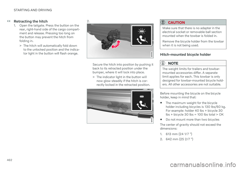
Retracting the hitch1. Open the tailgate. Press the button on therear, right-hand side of the cargo compart- ment and release. Pressing too long onthe button may prevent the hitch fromfolding in.
> The hitch will automatically fold downto the unlocked position and the indica- tor light in the button will flash orange. 2.
Secure the hitch into position by pushing it back to its retracted position under thebumper, where it will lock into place.
> The indicator light in the button will
now glow steadily if the hitch is cor- rectly locked in the retracted position.
CAUTION
Make sure that there is no adapter in the electrical socket or removable ball sectionmounted when the towbar is folded in. Remove the bicycle holder from the towbar when it is not being used.
Hitch-mounted bicycle holder
NOTE
The weight limits for trailers and towbar- mounted accessories differ. A separatelimit applies for each. This towbar is onlydesigned for towbar-mounted bicycle hold-ers. All other accessories are not suitable.
Before mounting the bicycle on the bicycle holder, keep in mind that:
The maximum weight for the bicycleholder including bicycles is 130 lbs/60 kg.For example: holder 40 lbs + bicycle 30lbs + bicycle 30 lbs = 100 lbs total > OK
Do not mount more than two bicycles
The center of gravity should not exceed thedimensions:
1. 613 mm (24 1/7 ")
2. 642 mm (25 2/7 ")
Page 465 of 693

STARTING AND DRIVING
}}
* Option/accessory.463
NOTE
Volvo recommends only using Volvo origi- nal accessories. Follow the instructionssupplied with the product.
CAUTION
Never use towbar adapters or towbar extenders
Only use ball mount for towing. Do notmount accessories directly on the ballmount. Use accessories designed tobe mounted in the towbar's squarebracket. Do not use accessoriesdesigned to be secured around the ballmount.
Loading the bicycle holderThe greater the distance between the load and the bicycle holder, the greater the load on thehitch and on the vehicle. Keep the following points in mind: Mount the heaviest bicycle closest to the vehicle.
If possible, mount the bicycles symmetri-cally, as close as possible to the center ofthe vehicle.
Remove loose objects from the bicycle,such as baskets, batteries or child seats.This will help reduce the load on the hitchand the bicycle holder.
Do not place a cover over the bicycle asthis could lead to increased load on thehitch.
Related information
Detachable towbar
* (p. 463)
Driving with a trailer (p. 465)
Detachable towbar
*
Volvo recommends the use of Volvo towbars that are specially designed for the vehicle.
NOTE
The optional detachable trailer hitch may not be available in all markets or on allmodels. Consult your Volvo retailer.
Ball holder
Cotter pin
Towbar assembly
Locking bolt
Safety wire attachment bracket
Page 466 of 693

||
STARTING AND DRIVING
* Option/accessory.
464
Installing the ball holder1. If necessary, remove the cotter pin from
the locking bolt and slide the locking bolt out of the towbar assembly.
2. Slide the ball holder into the towbar assembly.
3. Align the hole in the ball holder with the one in the towbar assembly.
4. Slide the locking bolt through the towbar assembly/ball holder.
5. Insert the cotter pin in the hole at the end of the locking bolt.
WARNING
Be sure the towbar is securely locked in position before attaching anything toit.
Always attach the trailer's safety wiresecurely to the towbar's safety wireattachment bracket.
Removing the ball holder1. Remove the cotter pin from the locking
bolt and slide the locking bolt out of theball holder/towbar assembly.
2. Pull the ball holder out of the towbar assembly.
WARNING
Damage may occur on the towbar if it is not used correctly or if incorrect or faultyaccessories are used, such as:
Overloading of accessory.
Use of incorrect or faulty accessory.
Accessory used for an incorrect pur- pose.
Use of weight-distributing towing sys-tem.
Incorrectly positioned ball mount; seegeometric limits for the towbar.
Stowing the ball holder
WARNING
When not in use, the detachable ball holder should always be properly stowed in thedesignated location under the floor of thecargo compartment.
Driving with a trailerWhen towing a trailer, the original ball holder or equivalent should be used.
The ball mount must fall within the geometric limits for the towbar, for both distance
and
height
. Geometric limits are described on a
type plate located on the towbar.
Related information
Retractable hitch
* (p. 461)
Driving with a trailer (p. 465)
Towing capacity and tongue weight (p. 667)
Page 467 of 693
STARTING AND DRIVING
}}
* Option/accessory.465
Driving with a trailer
There are a number of things to consider when towing a trailer, such as the towbar, thetrailer and how the load is distributed in thetrailer.
Load-carrying capacity is determined by the vehicle's curb weight. The total weight of allpassengers and any installed accessories, e.g.towbar, reduces the vehicle's load-carryingcapacity by the corresponding amount.
Towbars used on the vehicle must beapproved for the applicable use.
Distribute the load on the trailer so thatthe weight on the towbar complies withthe specified maximum towball weight.The tongue weight is calculated as part ofthe vehicle's payload.
Increase the tire pressure to the recom-mended pressure for a full load.
The engine is subjected to more load thanusual when towing a trailer.
Towing a trailer affects the vehicle's han-dling, durability and driving economy.
Do not drive with a heavy trailer when thevehicle is very new. Wait until the mileagehas reached at least 1000 km (620 miles).
On long and steep downgrades, the vehi-cle's brakes are subjected to much moreload than usual. When manually shifting, downshift and adapt speed accordingly.
Follow applicable regulations regarding permitted speed and weight.
Drive slowly when towing a trailer up along and steep incline.
The maximum trailer weights given onlyapply to altitudes up to 1000 meters(3280 feet) above sea level. At higher alti-tudes, engine power (and thus the vehi-cle's climbing ability) is decreased due tothe reduced air density, and the maximumtrailer weight must therefore be reduced.The weight of the vehicle and trailer mustbe decreased by 10% for each additional1000 m (3280 feet) or part thereof.
Avoid driving with a trailer on inclines ofmore than 12%.
Avoid overloading and other incorrect use.
The trailer's brakes must be balanced withthe vehicle's brakes to help ensure safestops (follow applicable local regulations).
NOTE
To facilitate towing a trailer in a vehicle equipped with pneumatic suspension
*,
select: the
Suspension ControlDynamic setting in Individual drive mode.
CAUTION
Bumper-attached trailer hitches must not be used on Volvos, nor shouldsafety chains be attached to thebumper.
Trailer hitches attaching to the vehiclerear axle must not be used.
Never connect a trailer's hydraulicbrake system directly to the vehiclebrake system, nor a trailer's lightingsystem directly to the vehicle lightingsystem. Consult your nearest author-ized Volvo retailer for correct installa-tion.
When towing a trailer, the trailer'ssafety chains or wire must be correctlyfastened to the attachment points pro-vided in the trailer hitch on the vehicle.The safety chain or wire must never befastened to or wound around the tow-ing ball.
NOTE
The optional detachable trailer hitch may not be available in all markets or on allmodels. Consult your Volvo retailer.
Page 468 of 693
||
STARTING AND DRIVING
* Option/accessory.
466
NOTE
Extreme weather conditions, towing a trailer, high altitude and lower fuel gradethan recommended are factors that cansignificantly increase the vehicle's fuel con-sumption.
Trailer weights
WARNING
Please adhere to the recommendations provided for trailer weight. If the recom-mendations are not followed, the vehicleand trailer may be difficult to control duringevasive maneuvers and braking.
NOTE
The specified maximum trailer weights are those permitted by Volvo. National vehicleregulations may set additional restrictionson trailer weight and speed. The trailerhitches may be certified for higher towingweights than the vehicle is permitted totow.
Self-leveling suspension *The vehicle's self-leveling system attempts to keep the vehicle at a constant level, regardlessof load (up to the maximum permitted weight).When the vehicle is stationary, the rear end of the vehicle will be slightly lowered, which isnormal.
Driving in hilly terrain or hot weatherIn certain conditions, there is a risk of over-heating when driving with a trailer. If overheat-ing of the engine and drive system is detected,a warning symbol will illuminate in the instru-ment panel and a message will appear. The automatic transmission selects the opti- mal gear for the current load and enginespeed.
Steep inclines
Do not lock the automatic transmission into a higher gear than what the engine can handle
‒
it is not always preferable to drive in highgears at low rpm.
Parking on a hill
1. Depress the brake pedal.
2. Apply the parking brake.
3. Put the gear selector in P.
4. Release the brake pedal.Put chocks behind the wheels when the vehi- cle is parked on a hill with a trailer attached.
Starting on a hill
1. Depress the brake pedal.
2. Put the gear selector in D.
3. Release the parking brake.
4. Release the brake pedal and start driving.
Related information
Trailer Stability Assist
* (p. 467)
Checking trailer lights (p. 468)
Towing capacity and tongue weight (p. 667)
Overheating of engine and transmission(p. 458)
Retractable hitch
* (p. 461)
Page 469 of 693
STARTING AND DRIVING
* Option/accessory.467
Trailer Stability Assist *
Trailer Stability Assist (TSA 16
) is a function
designed to help stabilize a vehicle that is towing a trailer when the vehicle and trailerhave begun to sway. The function is part of the Electronic Stability Control system ESC 17
.
Reasons for swayingA vehicle towing a trailer may begin to sway for various reasons. Normally this only occursat high speeds. However, if the trailer is over-loaded or unevenly distributed, e.g. too farback, there is a risk of swaying even at lowspeeds. Swaying may be caused by factors such as:
The vehicle and trailer are hit by a sudden, strong crosswind.
The vehicle and trailer are traveling on anuneven road or over a bump.
Sudden movements of the steering wheel.
Once swaying has begun, it can be difficult orimpossible to stop it. This makes the vehicleand trailer difficult to control and there is a riskof swerving into oncoming traffic or driving offthe road.
Trailer Stability Assist functionTrailer Stability Assist continuously monitorsthe vehicle's movements, particularly lateral movements. If swaying is detected, the brakesare applied individually on the front wheels,which has a stabilizing effect on the vehicleand trailer. This is often enough to enable thedriver to regain control of the vehicle. If the Trailer Stability Assist function's first attempt is not adequate to stop the swayingmotion, the brakes are applied on all wheelsand engine power is temporarily reduced. Asthe swaying motion begins to decrease andthe vehicle and trailer have once againbecome stable, TSA stops regulating thebrakes/engine power and the driver regainscontrol of the vehicle.
NOTE
Trailer Stability Assist is deactivated if the driver selects the sport mode by deactivat- ing
ESC in the center display's menu sys-
tem.
Trailer Stability Assist may not intervene if the driver tries to compensate for the swayingmotion by moving the steering wheel rapidly,because the system will then not be able todetermine if it is the trailer or the driver caus-ing the swaying. When Trailer Stability Assistis activated, the ESC symbolis displayed in the instrumentpanel.
Related information
Driving with a trailer (p. 465)
Electronic Stability Control (p. 281)
16
Trailer Stability Assist
17 Electronic Stability Control
Page 470 of 693

STARTING AND DRIVING
* Option/accessory.
468
Checking trailer lights
When connecting a trailer, make sure that all of the lights on the trailer are functioningbefore starting to drive.
Trailer turn signals and brake lightsIf one or more of the turn signals or brake lights on the trailer is not working, a symboland message will be displayed in the instru-ment panel. The other lights on the trailermust be checked manually by the driver beforethe vehicle is driven.
Symbol Message
Trailer turn indicator Right
turn indicator malfunction
Trailer turn indicator Left
turn indicator malfunction
Trailer brake light Malfunc-
tion
If any of the trailer's turn signal lights is not working, the turn signal symbol in the instru-ment panel will also flash more quickly thannormal.
Trailer rear fog lightWhen a trailer is connected, the vehicle's rearfog light may not illuminate and rear fog lightfunctionality is instead transferred to the trailer. If this is the case, check to see if thetrailer is equipped with a rear fog light beforeactivating the vehicle's fog lights when drivingwith a trailer to help ensure safe operation.
Checking trailer lights
*
Automatic check
When the trailer has been connected to the vehicle's electrical system, its lights can bechecked by automatically activating them.This function helps the driver check that thetrailer's lights are functioning correctly beforestarting to drive. In order to perform this check, the vehicle must be switched off.
1. When a trailer is connected to the towbar,
the message
Automatic Trailer Lamp
Check will appear in the instrument panel.
2. Acknowledge the message by pressing the O button on the right-side steering
wheel keypad.
> The light check will begin.
3. Get out of the vehicle to perform the check.
> All of the lights on the trailer will beginflashing, and then illuminate separately one at a time.
4. Visually check that all of the trailer's lights are functioning correctly. 5. After a short time, all of the trailer's lights
will start flashing again.
> The light check is completed.
Disabling the automatic check
The automatic light check can be disabled in the center display. 1.Tap
Settings in the Top view.
2. Tap
My CarLights and Lighting.
3. Deselect
Automatic Trailer Lamp
Check.
Manual check
If the automatic check has been disabled, the check can be started manually. 1. Tap
Settings in the Top view.
2. Tap
My CarLights and Lighting.
3. Select
Manual Trailer Lamp Check.
> The light check will begin. Get out of the vehicle to perform the check.
Related information
Driving with a trailer (p. 465)