sensor VOLVO XC90 TWIN ENGINE HYBRID 2017 Owners Manual
[x] Cancel search | Manufacturer: VOLVO, Model Year: 2017, Model line: XC90 TWIN ENGINE HYBRID, Model: VOLVO XC90 TWIN ENGINE HYBRID 2017Pages: 584, PDF Size: 14.2 MB
Page 4 of 584
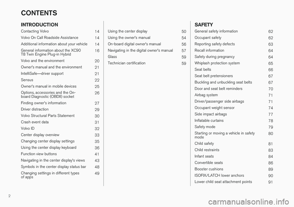
2
INTRODUCTION
Contacting Volvo14
Volvo On Call Roadside Assistance14
Additional information about your vehicle14
General information about the XC90T8 Twin Engine Plug-in Hybrid16
Volvo and the environment20
Owner's manual and the environment21
IntelliSafe—driver support21
Sensus22
Owner's manual in mobile devices25
Options, accessories and the On-board Diagnostic (OBDII) socket 26
Finding owner's information27
Driver distraction29
Volvo Structural Parts Statement30
Crash event data31
Volvo ID32
Center display overview33
Changing center display settings35
Using the center display keyboard36
Function view buttons41
Navigating in the center display's views43
Symbols in the center display status bar48
Changing settings in different typesof apps49
Using the center display50
Using the owner's manual54
On-board digital owner's manual56
Navigating in the digital owner's manual57
Glass59
Technician certification59
SAFETY
General safety information62
Occupant safety62
Reporting safety defects63
Recall information64
Safety during pregnancy64
Whiplash protection system65
Seat belts66
Seat belt pretensioners67
Buckling and unbuckling seat belts67
Door and seat belt reminders70
Airbag system71
Driver/passenger side airbags71
Occupant weight sensor74
Side impact airbags77
Inflatable curtains78
Safety mode79
Starting or moving a vehicle in safetymode80
Child safety81
Child restraints83
Infant seats84
Convertible seats86
Booster cushions89
ISOFIX/LATCH lower anchors90
Lower child seat attachment points91
CONTENTS
Page 5 of 584
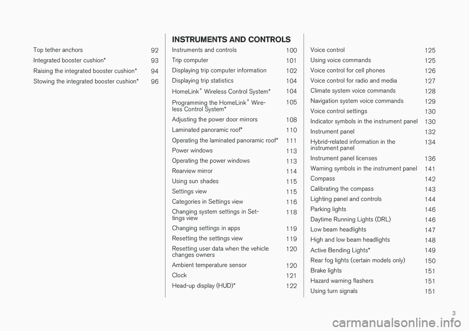
3
Top tether anchors92
Integrated booster cushion*93
Raising the integrated booster cushion*94
Stowing the integrated booster cushion*96
INSTRUMENTS AND CONTROLS
Instruments and controls100
Trip computer101
Displaying trip computer information102
Displaying trip statistics104
HomeLink® Wireless Control System*104
Programming the HomeLink® Wire-less Control System*105
Adjusting the power door mirrors108
Laminated panoramic roof*110
Operating the laminated panoramic roof*111
Power windows113
Operating the power windows113
Rearview mirror114
Using sun shades115
Settings view115
Categories in Settings view116
Changing system settings in Set-tings view118
Changing settings in apps119
Resetting the settings view119
Resetting user data when the vehiclechanges owners120
Ambient temperature sensor120
Clock121
Head-up display (HUD)*122
Voice control125
Using voice commands125
Voice control for cell phones126
Voice control for radio and media127
Climate system voice commands128
Navigation system voice commands129
Voice control settings130
Indicator symbols in the instrument panel130
Instrument panel132
Hybrid-related information in theinstrument panel134
Instrument panel licenses136
Warning symbols in the instrument panel141
Compass142
Calibrating the compass143
Lighting panel and controls144
Parking lights146
Daytime Running Lights (DRL)146
Low beam headlights147
High and low beam headlights148
Active Bending Lights*149
Rear fog lights (certain models only)150
Brake lights151
Hazard warning flashers151
Using turn signals151
Page 6 of 584
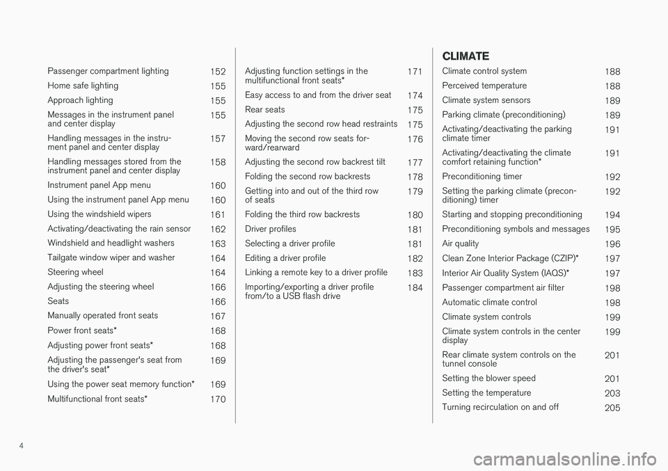
4
Passenger compartment lighting152
Home safe lighting155
Approach lighting155
Messages in the instrument paneland center display155
Handling messages in the instru-ment panel and center display157
Handling messages stored from theinstrument panel and center display158
Instrument panel App menu160
Using the instrument panel App menu160
Using the windshield wipers161
Activating/deactivating the rain sensor162
Windshield and headlight washers163
Tailgate window wiper and washer164
Steering wheel164
Adjusting the steering wheel166
Seats166
Manually operated front seats167
Power front seats*168
Adjusting power front seats*168
Adjusting the passenger's seat fromthe driver's seat*169
Using the power seat memory function*169
Multifunctional front seats*170
Adjusting function settings in themultifunctional front seats*171
Easy access to and from the driver seat174
Rear seats175
Adjusting the second row head restraints175
Moving the second row seats for-ward/rearward176
Adjusting the second row backrest tilt177
Folding the second row backrests178
Getting into and out of the third rowof seats179
Folding the third row backrests180
Driver profiles181
Selecting a driver profile181
Editing a driver profile182
Linking a remote key to a driver profile183
Importing/exporting a driver profilefrom/to a USB flash drive184
CLIMATE
Climate control system188
Perceived temperature188
Climate system sensors189
Parking climate (preconditioning)189
Activating/deactivating the parkingclimate timer191
Activating/deactivating the climatecomfort retaining function*191
Preconditioning timer192
Setting the parking climate (precon-ditioning) timer192
Starting and stopping preconditioning194
Preconditioning symbols and messages195
Air quality196
Clean Zone Interior Package (CZIP)*197
Interior Air Quality System (IAQS)*197
Passenger compartment air filter198
Automatic climate control198
Climate system controls199
Climate system controls in the centerdisplay199
Rear climate system controls on thetunnel console201
Setting the blower speed201
Setting the temperature203
Turning recirculation on and off205
Page 9 of 584
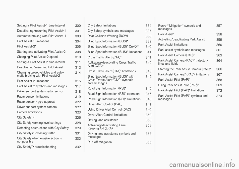
7
Setting a Pilot Assist-1 time interval300
Deactivating/resuming Pilot Assist-1301
Automatic braking with Pilot Assist-1303
Pilot Assist-1 limitations304
Pilot Assist-2*305
Starting and activating Pilot Assist-2308
Changing Pilot Assist-2 speed310
Setting a Pilot Assist-2 time interval311
Deactivating/resuming Pilot Assist312
Changing target vehicles and auto-matic braking with Pilot Assist-2314
Pilot Assist-2 limitations315
Pilot Assist-2 symbols and messages317
Driver support system radar sensor318
Radar sensor limitations319
Radar sensor - type approval322
Driver support system camera322
Camera limitations323
City Safety™326
City Safety warning level settings328
Detecting obstructions with City Safety329
City Safety in crossing traffic331
City Safety when evasive action isnot possible332
City Safety™ troubleshooting332
City Safety limitations334
City Safety symbols and messages337
Rear Collision Warning (RCW)338
Blind Spot Information (BLIS)*339
Blind Spot Information (BLIS)* On/Off340
Blind Spot Information (BLIS)* limitations341
Cross Traffic Alert (CTA)*341
Activating/deactivating Cross TrafficAlert (CTA)*342
Cross Traffic Alert (CTA)* limitations343
Blind Spot Information (BLIS)* withCross Traffic Alert (CTA)* symbolsand messages
345
Road Sign Information (RSI)*346
Road Sign Information (RSI)* operation346
Road Sign Information (RSI)* limitations348
Driver Alert Control (DAC)348
Using Driver Alert Control (DAC)349
Driver Alert Control limitations350
Driving lane assistance350
Activating/deactivating LaneKeeping Aid (LKA)352
Driving lane assistance symbols andmessages353
Run-off Mitigation355
Run-off Mitigation* symbols andmessages357
Park Assist*358
Activating/deactivating Park Assist359
Park Assist limitations360
Park assist symbols and messages361
Park Assist Camera (PAC)*362
Park Assist Camera (PAC)* trajectorylines and fields364
Starting the Park Assist Camera (PAC)*366
Park Assist Camera* (PAC) limitations367
Park Assist Pilot (PAP)*368
Using Park Assist Pilot (PAP)*369
Park Assist Pilot (PAP)* limitations372
Park Assist Pilot (PAP)* symbols andmessages374
Page 32 of 584
||
INTRODUCTION
30
WARNING
The driver is always responsible for operatingthe vehicle in a safe manner and for comply-ing with current statutes and regulations.
It is also essential to maintain and service thevehicle according to Volvo's recommendationsas stated in the owner's information and theservice and warranty booklet.
If the on-board information differs from theprinted owner's manual, the printed informa-tion always takes precedence.
Related information
•Volvo Structural Parts Statement (p. 30)
Volvo Structural Parts Statement
Volvo has always been and continues to be aleader in automotive safety.
Volvo engineers and manufactures vehiclesdesigned to help protect vehicle occupants in theevent of a collision.
Volvos are designed to absorb the impact of acollision. This energy absorption system including,but not limited to, structural components such asbumper reinforcement bars, bumper energyabsorbers, frames, rails, fender aprons, A-pillars,B-pillars and body panels must work together tomaintain cabin integrity and protect the vehicleoccupants.
The supplemental restraint system including butnot limited to air bags, side curtain air bags, anddeployment sensors work together with theabove components to provide proper timing forair bag deployment.
Due to the above, Volvo Car USA does not sup-port the use of aftermarket, alternative or any-thing other than original Volvo parts for collisionrepair.
Volvo Car USA also recommends using Volvo-approved replacement glass. The use of after-market glass, particularly a windshield, can havean adverse effect on collision avoidance andadvanced lighting systems.
In addition Volvo does not support the use or re-use of structural components from an existing
vehicle that has been previously damaged.Although these parts may appear equivalent, it isdifficult to tell if the parts have been previouslyreplaced with non-OE parts or if the part hasbeen damaged as a result of a prior collision. Thequality of these used parts may also have beenaffected due to environmental exposure.
Related information
•Crash event data (p. 31)
•Contacting Volvo (p. 14)
Page 61 of 584
INTRODUCTION
* Option/accessory, for more information, see Introduction.59
Using the search function
1.Tap the magnifying glass icon () in theowner's manual's upper menu. A keyboardwill appear at the bottom of the screen.
2.Enter a word, e.g., "seat belt."
> Suggested articles will be displayed asmore characters are entered.
3. Confirm by tapping the article. To leavesearch mode tap the up-arrow next to thesearch box.
Related information
•On-board digital owner's manual (p. 56)
•Using the center display keyboard (p. 36)
Glass
Laminated glass
The windshield and panoramic roof* are made oflaminated glass, which is reinforced to help pre-vent break-ins and to provide additional sound-proofing. Laminated glass is optional for theother side windows.
Laminated glass symbol5
Related information
•Laminated panoramic roof* (p. 110)
•Power windows (p. 113)
•Defrosting windows and mirrors (p. 206)
•Using sun shades (p. 115)
•Rearview mirror (p. 114)
•Power windows (p. 113)
•Head-up display (HUD)* (p. 122)
•Activating/deactivating the rain sensor(p. 162)
•Windshield and headlight washers (p. 163)
•Tailgate window wiper and washer (p. 164)
•Defrosting windows and mirrors (p. 206)
Technician certification
In addition to Volvo factory training, Volvo sup-ports certification by the National Institute forAutomotive Service Excellence (A.S.E.).
Certified technicians have demonstrated a highdegree of competence in specific areas. Besidespassing exams, each technician must also haveworked in the field for two or more years before acertificate is issued. These professional techni-cians are best able to analyze vehicle problemsand perform the necessary maintenance proce-dures to keep your Volvo at peak operating con-dition.
XC90 T8 Twin Engine Plug-in Hybrid
Technicians performing work on a vehicle withelectrification should also have the necessarytraining and specialized certification required forperforming repairs and/or maintenance on avehicle with electrification.
WARNING
A number of electrical components in theXC90 T8 Twin Engine Plug-in Hybrid usehigh-voltage current and can be extremelydangerous if handled incorrectly. These com-ponents and any orange wiring in the vehiclemay only be handled by trained and qualifiedVolvo service technicians.
5This symbol is not shown on the windshield or moon roof/panoramic roof.
Page 64 of 584
SAFETY
62
General safety information
The vehicle is equipped with a number of safetysystems for the driver and passengers.
In the event of an accident, there are a number ofsensors in the vehicle that react and triggersafety systems such as Roll Stability Control, air-bags, seat belt pretensioners, etc., depending onthe severity of the collision. There are alsomechanical systems such as the WhiplashProtection System.
Warning symbol in the instrument panel
The warning symbol in the instrumentpanel illuminates when the ignition is inmode II or higher. It will go out afterapprox. 6 seconds if no faults aredetected in the airbag system.
WARNING
•If the SRS warning light stays on after theengine has started or if it illuminateswhile you are driving, have the vehicleinspected by a trained and qualified Volvoservice technician as soon as possible.
•Never try to repair any component or partof the SRS yourself. Any interference inthe system could cause malfunction andserious injury. All work on these systemsshould be performed by a trained andqualified Volvo service technician.
If the dedicated warning symbol is notfunctioning, the general warning sym-bol will illuminate instead and the samemessage will be displayed in the instru-ment panel.
Related information
•Safety during pregnancy (p. 64)
•Seat belts (p. 66)
•Airbag system (p. 71)
•Safety mode (p. 79)
•Whiplash protection system (p. 65)
•Child safety (p. 81)
Occupant safety
Safety is Volvo's cornerstone.
Volvo's concern for safety
Our concern for safety dates back to 1927 whenthe first Volvo rolled off the production line.Three-point seat belts (a Volvo invention), safetycages, and energy-absorbing impact zones weredesigned into Volvo vehicles long before it wasfashionable or required by government regulation.
We will not compromise our commitment tosafety. We continue to seek out new safety fea-tures and to refine those already in our vehicles.You can help. We would appreciate hearing yoursuggestions about improving automobile safety.We also want to know if you ever have a safetyconcern with your vehicle. Call us in the U.S. at:1-800-458-1552 or in Canada at:1-800-663-8255.
Page 74 of 584
||
SAFETY
72
The location of the front airbags is indicated bySRS AIRBAG embossed on the steering wheelpad and above the glove compartment, and bydecals on both sun visors and on the front andfar right side of the dash.
The driver's side front airbag is folded andlocated in the steering wheel hub.
The knee airbag is folded on the underside ofthe dashboard on the driver's side. The textAIRBAG is embossed on the panel.
The passenger's side front airbag is foldedbehind a panel located above the glove compart-ment.
WARNING
•The airbags in the vehicle are designed tobe a SUPPLEMENT to–not a replace-ment for–the three-point seat belts. Formaximum protection, wear seat belts at alltimes. Be aware that no system can pre-vent all possible injuries that may occur inan accident.
•Never drive with your hands on the steer-ing wheel pad/airbag housing.
•The front airbags are designed to helpprevent serious injury. Deployment occursvery quickly and with considerable force.During normal deployment and depend-ing on variables such as seating position,one may experience abrasions, bruises,swellings, or other injuries as a resultfrom deployment of one or both of theairbags.
•When installing any accessory equipment,make sure that the front airbag system isnot damaged. Any interference in the sys-tem could cause malfunction.
Front airbag deployment
•The front airbags are designed to deploy dur-ing certain frontal or front-angular collisions,impacts, or decelerations, depending on thecrash severity, angle, speed and objectimpacted. The airbags may also deploy in
certain non-frontal collisions where rapiddeceleration occurs.
•The airbag system sensors, which trigger thefront airbags, are designed to react to boththe impact of the collision and the inertialforces generated by it, and to determine ifthe intensity of the collision is sufficient forthe seat belt pretensioners and/or airbags tobe deployed.
However, not all frontal collisions activate thefront airbags.
•If the collision involves a nonrigid object (e.g.,a snow drift or bush), or a rigid, fixed objectat a low speed, the front airbags will not nec-essarily deploy.
•Front airbags do not normally deploy in aside impact collision, in a collision from therear or in a rollover situation.
•The amount of damage to the bodyworkdoes not reliably indicate if the airbagsshould have deployed or not.
Page 75 of 584
SAFETY
}}
73
NOTE
•Deployment of front airbags occurs onlyone time during an accident. In a collisionwhere deployment occurs, the airbagsand seat belt pretensioners activate.Some noise occurs and a small amountof powder is released. The release of thepowder may appear as smoke-like matter.This is a normal characteristic and doesnot indicate fire.
•Volvo's front airbags use special sensorsthat are integrated with the front seatbuckles. The point at which the airbagdeploys is determined by whether or notthe seat belt is being used, as well as theseverity of the collision.
•Collisions can occur where only one ofthe airbags deploys. If the impact is lesssevere, but severe enough to present aclear injury risk, the airbags are triggeredat partial capacity. If the impact is moresevere, the airbags are triggered at fullcapacity.
WARNING
•Do not use child safety seats or childbooster cushions/backrests in the frontpassenger's seat. We also recommendthat occupants under 4 feet 7 inches(140 cm) in height who have outgrownthese devices sit in the rear seat with theseat belt fastened. See also the Occu-pant Weight Sensor information,.
•Never drive with the airbags deployed.The fact that they hang out can impair thesteering of your vehicle. Other safety sys-tems can also be damaged.
•The smoke and dust formed when theairbags are deployed can cause skin andeye irritation in the event of prolongedexposure.
Should you have questions about any componentin the SRS system, please contact a trained andqualified Volvo service technician or Volvo cus-tomer support:
In the USA
Volvo Car USA, LLC
Customer Care Center
1 Volvo Drive
P.O. Box 914
Rockleigh, New Jersey 07647
1-800-458-1552
www.volvocars.com/us
In Canada
Volvo Cars of Canada Corp.
National Customer Service
9130 Leslie Street, Suite 101
Richmond Hill, Ontario L4B 0B9
1-800-663-8255
www.volvocars.com/ca
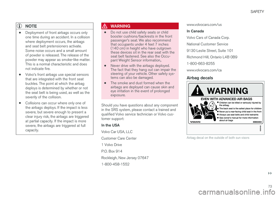
Airbag decals
Airbag decal on the outside of both sun visors
Page 76 of 584
||
SAFETY
74
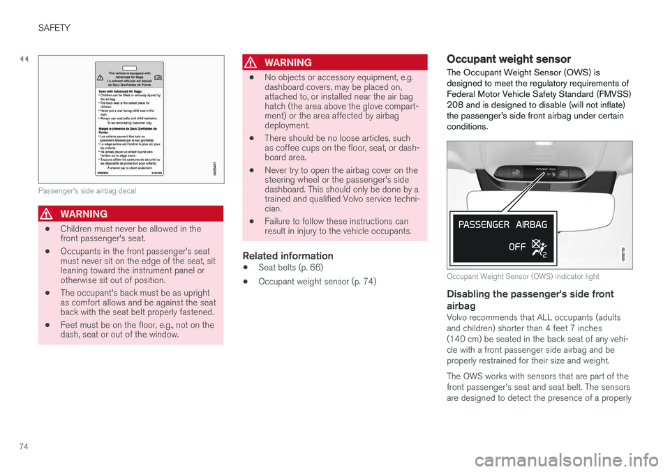
Passenger's side airbag decal
WARNING
•Children must never be allowed in thefront passenger's seat.
•Occupants in the front passenger's seatmust never sit on the edge of the seat, sitleaning toward the instrument panel orotherwise sit out of position.
•The occupant's back must be as uprightas comfort allows and be against the seatback with the seat belt properly fastened.
•Feet must be on the floor, e.g., not on thedash, seat or out of the window.
WARNING
•No objects or accessory equipment, e.g.dashboard covers, may be placed on,attached to, or installed near the air baghatch (the area above the glove compart-ment) or the area affected by airbagdeployment.
•There should be no loose articles, suchas coffee cups on the floor, seat, or dash-board area.
•Never try to open the airbag cover on thesteering wheel or the passenger's sidedashboard. This should only be done by atrained and qualified Volvo service techni-cian.
•Failure to follow these instructions canresult in injury to the vehicle occupants.
Related information
•Seat belts (p. 66)
•Occupant weight sensor (p. 74)
Occupant weight sensor
The Occupant Weight Sensor (OWS) isdesigned to meet the regulatory requirements ofFederal Motor Vehicle Safety Standard (FMVSS)208 and is designed to disable (will not inflate)the passenger's side front airbag under certainconditions.
Occupant Weight Sensor (OWS) indicator light
Disabling the passenger's side front
airbag
Volvo recommends that ALL occupants (adultsand children) shorter than 4 feet 7 inches(140 cm) be seated in the back seat of any vehi-cle with a front passenger side airbag and beproperly restrained for their size and weight.
The OWS works with sensors that are part of thefront passenger's seat and seat belt. The sensorsare designed to detect the presence of a properly