YAMAHA AEROX50 2014 Service Manual
Manufacturer: YAMAHA, Model Year: 2014, Model line: AEROX50, Model: YAMAHA AEROX50 2014Pages: 78, PDF Size: 4.05 MB
Page 41 of 78
PERIODIC MAINTENANCE AND ADJUSTMENT
6-6
6
EAU18742
Removing and installing the
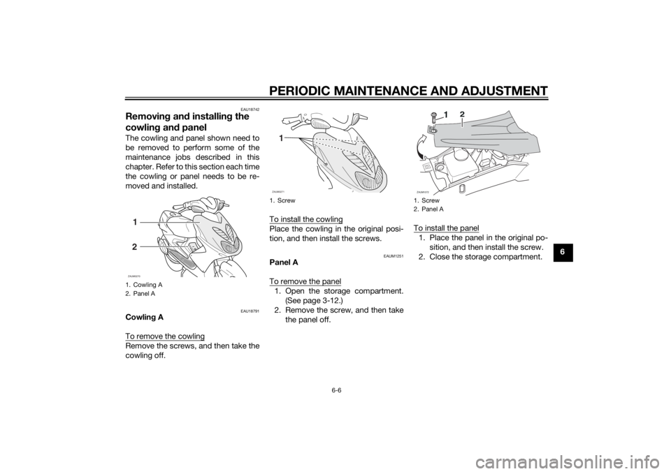
cowling and panelThe cowling and panel shown need to
be removed to perform some of the
maintenance jobs described in this
chapter. Refer to this section each time
the cowling or panel needs to be re-
moved and installed.
EAU18791
Cowling A
To remove the cowlingRemove the screws, and then take the
cowling off.To install the cowling
Place the cowling in the original posi-
tion, and then install the screws.
EAUM1251
Panel A
To remove the panel1. Open the storage compartment.
(See page 3-12.)
2. Remove the screw, and then take
the panel off.To install the panel
1. Place the panel in the original po-
sition, and then install the screw.
2. Close the storage compartment.
1. Cowling A
2. Panel A1
2ZAUM0270
1. Screw
1ZAUM0271
1. Screw
2. Panel AZAUM1072
1
2
U1GBE0E0.book Page 6 Wednesday, June 26, 2013 4:04 PM
Page 42 of 78
PERIODIC MAINTENANCE AND ADJUSTMENT
6-7
6
EAUM3251
Checking the spark plugThe spark plug is an important engine
component, which is easy to check.
Since heat and deposits will cause any
spark plug to slowly erode, the spark
plug should be removed and checked
in accordance with the periodic main-
tenance and lubrication chart. In addi-
tion, the condition of the spark plug
can reveal the condition of the engine.
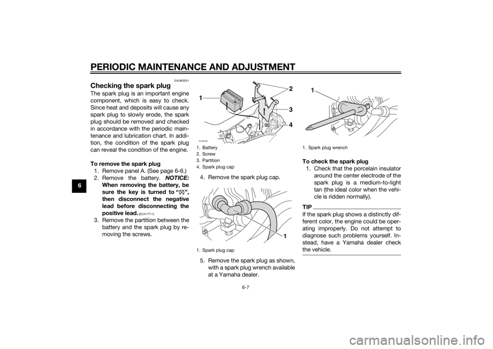
To remove the spark plug
1. Remove panel A. (See page 6-6.)
2. Remove the battery. NOTICE:
When removing the battery, be
sure the key is turned to “ ”,
then disconnect the negative
lead before disconnecting the
positive lead.
[ECA17711]
3. Remove the partition between the
battery and the spark plug by re-
moving the screws.4. Remove the spark plug cap.
5. Remove the spark plug as shown,
with a spark plug wrench available
at a Yamaha dealer.To check the spark plug
1. Check that the porcelain insulator
around the center electrode of the
spark plug is a medium-to-light
tan (the ideal color when the vehi-
cle is ridden normally).
TIPIf the spark plug shows a distinctly dif-
ferent color, the engine could be oper-
ating improperly. Do not attempt to
diagnose such problems yourself. In-
stead, have a Yamaha dealer check
the vehicle.
1. Battery
2. Screw
3. Partition
4. Spark plug cap
1. Spark plug capZAUM1080
3 142
1. Spark plug wrench
U1GBE0E0.book Page 7 Wednesday, June 26, 2013 4:04 PM
Page 43 of 78
PERIODIC MAINTENANCE AND ADJUSTMENT
6-8
6 2. Check the spark plug for electrode
erosion and excessive carbon or
other deposits, and replace it if
necessary.
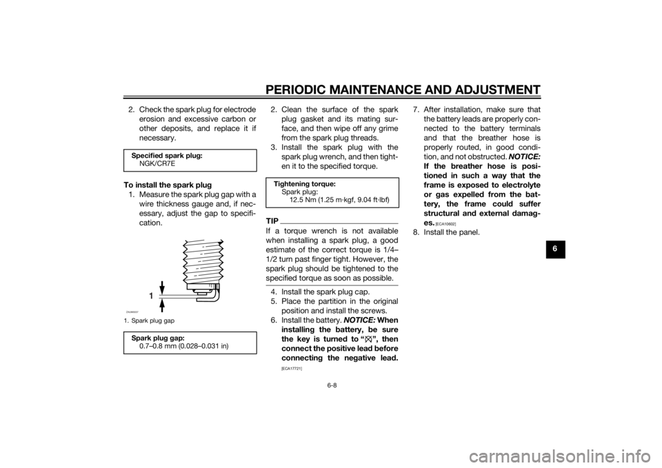
To install the spark plug
1. Measure the spark plug gap with a
wire thickness gauge and, if nec-
essary, adjust the gap to specifi-
cation.2. Clean the surface of the spark
plug gasket and its mating sur-
face, and then wipe off any grime
from the spark plug threads.
3. Install the spark plug with the
spark plug wrench, and then tight-
en it to the specified torque.
TIPIf a torque wrench is not available
when installing a spark plug, a good
estimate of the correct torque is 1/4…
1/2 turn past finger tight. However, the
spark plug should be tightened to the
specified torque as soon as possible.4. Install the spark plug cap.
5. Place the partition in the original
position and install the screws.
6. Install the battery. NOTICE: When
installing the battery, be sure
the key is turned to “ ”, then
connect the positive lead before
connecting the negative lead.
[ECA17721]
7. After installation, make sure that
the battery leads are properly con-
nected to the battery terminals
and that the breather hose is
properly routed, in good condi-
tion, and not obstructed. NOTICE:
If the breather hose is posi-
tioned in such a way that the
frame is exposed to electrolyte
or gas expelled from the bat-
tery, the frame could suffer
structural and external damag-
es.
[ECA10602]
8. Install the panel.
Specified spark plug:
NGK/CR7E1. Spark plug gapSpark plug gap:
0.7–0.8 mm (0.028–0.031 in)
1
ZAUM0037
Tightening torque:
Spark plug:
12.5 Nm (1.25 m·kgf, 9.04 ft·lbf)
U1GBE0E0.book Page 8 Wednesday, June 26, 2013 4:04 PM
Page 44 of 78
PERIODIC MAINTENANCE AND ADJUSTMENT
6-9
6
EAUM3170
Engine oil and oil strainerThe engine oil level should be checked
before each ride. In addition, the oil
must be changed and the oil strainer
cleaned at the intervals specified in the
periodic maintenance and lubrication
chart.
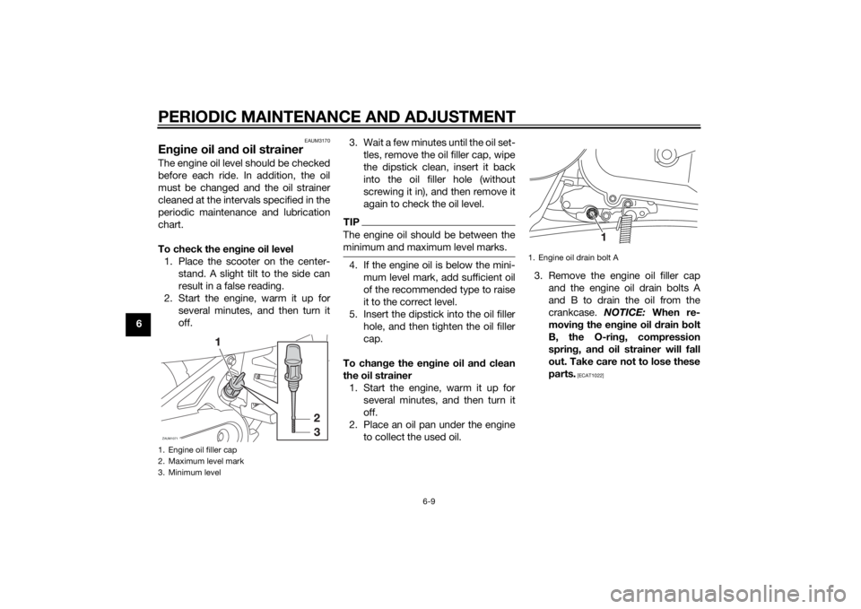
To check the engine oil level
1. Place the scooter on the center-
stand. A slight tilt to the side can
result in a false reading.
2. Start the engine, warm it up for
several minutes, and then turn it
off.3. Wait a few minutes until the oil set-
tles, remove the oil filler cap, wipe
the dipstick clean, insert it back
into the oil filler hole (without
screwing it in), and then remove it
again to check the oil level.
TIPThe engine oil should be between the
minimum and maximum level marks.4. If the engine oil is below the mini-
mum level mark, add sufficient oil
of the recommended type to raise
it to the correct level.
5. Insert the dipstick into the oil filler
hole, and then tighten the oil filler
cap.
To change the engine oil and clean
the oil strainer
1. Start the engine, warm it up for
several minutes, and then turn it
off.
2. Place an oil pan under the engine
to collect the used oil.3. Remove the engine oil filler cap
and the engine oil drain bolts A
and B to drain the oil from the
crankcase. NOTICE: When re-
moving the engine oil drain bolt
B, the O-ring, compression
spring, and oil strainer will fall
out. Take care not to lose these
parts.
[ECAT1022]
1. Engine oil filler cap
2. Maximum level mark
3. Minimum levelZAUM1071
1. Engine oil drain bolt A
U1GBE0E0.book Page 9 Wednesday, June 26, 2013 4:04 PM
Page 45 of 78
PERIODIC MAINTENANCE AND ADJUSTMENT
6-10
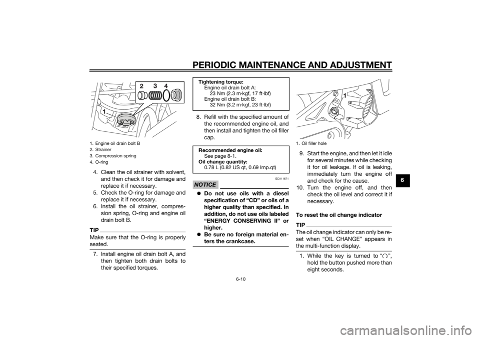
6 4. Clean the oil strainer with solvent,
and then check it for damage and
replace it if necessary.
5. Check the O-ring for damage and
replace it if necessary.
6. Install the oil strainer, compres-
sion spring, O-ring and engine oil
drain bolt B.
TIPMake sure that the O-ring is properly
seated.7. Install engine oil drain bolt A, and
then tighten both drain bolts to
their specified torques.8. Refill with the specified amount of
the recommended engine oil, and
then install and tighten the oil filler
cap.
NOTICE
ECA11671
Do not use oils with a diesel
specification of “CD” or oils of a
higher quality than specified. In
addition, do not use oils labeled
“ENERGY CONSERVING II” or
higher.
Be sure no foreign material en-
ters the crankcase.
9. Start the engine, and then let it idle
for several minutes while checking
it for oil leakage. If oil is leaking,
immediately turn the engine off
and check for the cause.
10. Turn the engine off, and then
check the oil level and correct it if
necessary.
To reset the oil change indicatorTIPThe oil change indicator can only be re-
set when “OIL CHANGE” appears in
the multi-function display.1. While the key is turned to “ ”,
hold the button pushed more than
eight seconds.
1. Engine oil drain bolt B
2. Strainer
3. Compression spring
4. O-ring
Tightening torque:
Engine oil drain bolt A:
23 Nm (2.3 m·kgf, 17 ft·lbf)
Engine oil drain bolt B:
32 Nm (3.2 m·kgf, 23 ft·lbf)
Recommended engine oil:
See page 8-1.
Oil change quantity:
0.78 L (0.82 US qt, 0.69 Imp.qt)
1. Oil filler hole
U1GBE0E0.book Page 10 Wednesday, June 26, 2013 4:04 PM
Page 46 of 78
PERIODIC MAINTENANCE AND ADJUSTMENT
6-11
62. Release the button, and the oil
change indicator will go off.
EAUT1562
Final transmission oilThe final transmission case must be
checked for oil leakage before each
ride. If any leakage is found, have a
Yamaha dealer check and repair the
scooter. In addition, the final transmis-
sion oil must be changed as follows at
the intervals specified in the periodic
maintenance and lubrication chart.
1. Start the engine, warm it up by rid-
ing the scooter for several min-
utes, and then stop the engine.
2. Place the scooter on the center-
stand.
3. Place an oil pan under the final
transmission case to collect the
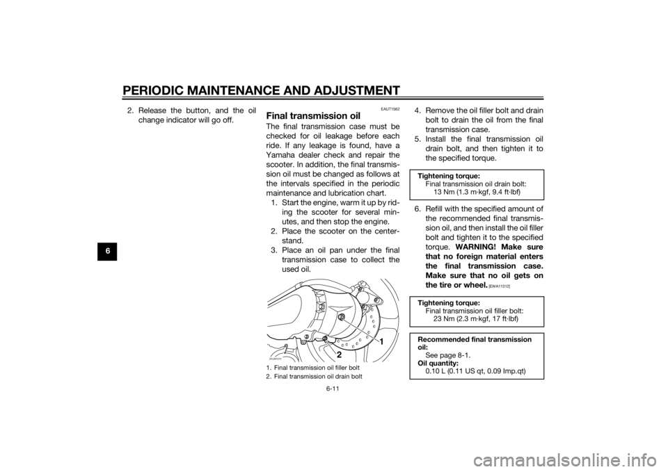
used oil.4. Remove the oil filler bolt and drain
bolt to drain the oil from the final
transmission case.
5. Install the final transmission oil
drain bolt, and then tighten it to
the specified torque.
6. Refill with the specified amount of
the recommended final transmis-
sion oil, and then install the oil filler
bolt and tighten it to the specified
torque. WARNING! Make sure
that no foreign material enters
the final transmission case.
Make sure that no oil gets on
the tire or wheel.
[EWA11312]
1. Final transmission oil filler bolt
2. Final transmission oil drain boltZAUM1073
2
1
Tightening torque:
Final transmission oil drain bolt:
13 Nm (1.3 m·kgf, 9.4 ft·lbf)
Tightening torque:
Final transmission oil filler bolt:
23 Nm (2.3 m·kgf, 17 ft·lbf)
Recommended final transmission
oil:
See page 8-1.
Oil quantity:
0.10 L (0.11 US qt, 0.09 Imp.qt)
U1GBE0E0.book Page 11 Wednesday, June 26, 2013 4:04 PM
Page 47 of 78
PERIODIC MAINTENANCE AND ADJUSTMENT
6-12
6 7. Check the final transmission case
for oil leakage. If oil is leaking,
check for the cause.
EAU20071
CoolantThe coolant level should be checked
before each ride. In addition, the cool-
ant must be changed at the intervals
specified in the periodic maintenance
and lubrication chart.
EAUM3180
To check the coolant level
1. Place the vehicle on a level sur-
face and hold it in an upright posi-
tion.TIPThe coolant level must be
checked on a cold engine since
the level varies with engine tem-
perature.
Make sure that the vehicle is posi-
tioned straight up when checking
the coolant level. A slight tilt to the
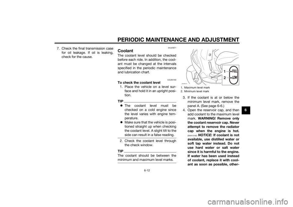
side can result in a false reading.2. Check the coolant level through
the check window.TIPThe coolant should be between the
minimum and maximum level marks.
3. If the coolant is at or below the
minimum level mark, remove the
panel A. (See page 6-6.)
4. Open the reservoir cap, and then
add coolant to the maximum level
mark. WARNING! Remove only
the coolant reservoir cap. Never
attempt to remove the radiator
cap when the engine is hot.
[EWA15162]
NOTICE: If coolant is not
available, use distilled water or
soft tap water instead. Do not
use hard water or salt water
since it is harmful to the engine.
If water has been used instead
of coolant, replace it with cool-
ant as soon as possible, other-
1. Maximum level mark
2. Minimum level markZAUM1074
1
2
FULLFULLLOWLOW
U1GBE0E0.book Page 12 Wednesday, June 26, 2013 4:04 PM
Page 48 of 78
PERIODIC MAINTENANCE AND ADJUSTMENT
6-13
6wise the cooling system will not
be protected against frost and
corrosion. If water has been
added to the coolant, have a
Yamaha dealer check the anti-
freeze content of the coolant as
soon as possible, otherwise the
effectiveness of the coolant will
be reduced.
[ECA10473]
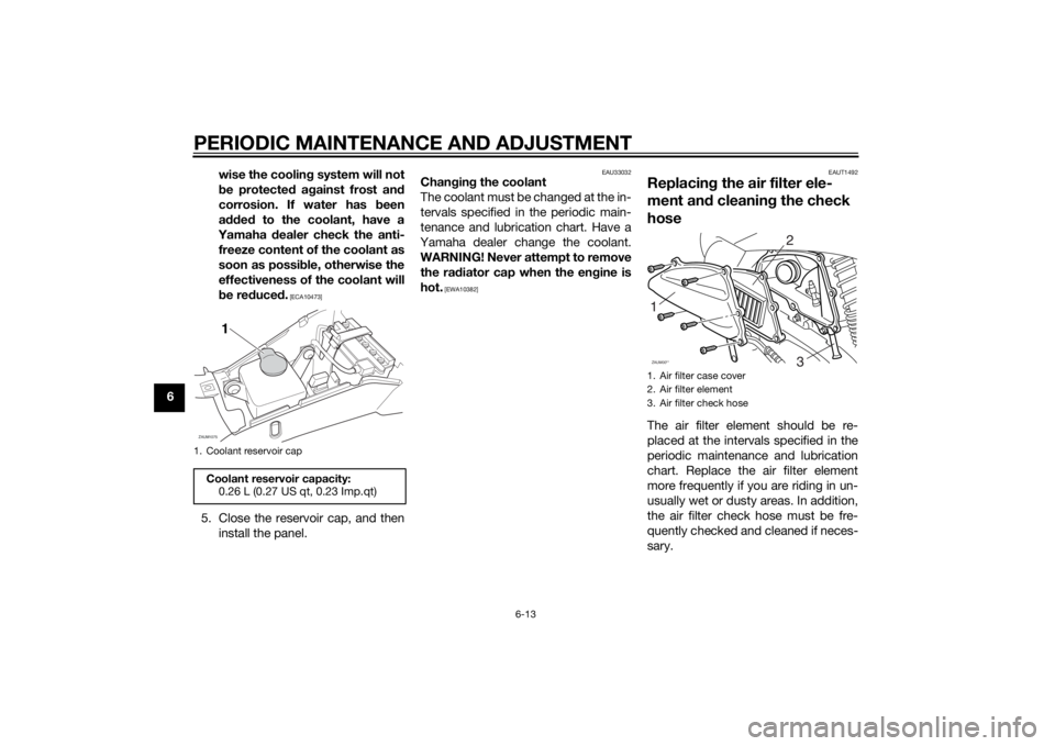
5. Close the reservoir cap, and then
install the panel.
EAU33032
Changing the coolant
The coolant must be changed at the in-
tervals specified in the periodic main-
tenance and lubrication chart. Have a
Yamaha dealer change the coolant.
WARNING! Never attempt to remove
the radiator cap when the engine is
hot.
[EWA10382]EAUT1492
Replacing the air filter ele-
ment and cleaning the check
hoseThe air filter element should be re-
placed at the intervals specified in the
periodic maintenance and lubrication
chart. Replace the air filter element
more frequently if you are riding in un-
usually wet or dusty areas. In addition,
the air filter check hose must be fre-
quently checked and cleaned if neces-
sary.
1. Coolant reservoir capCoolant reservoir capacity:
0.26 L (0.27 US qt, 0.23 Imp.qt)ZAUM1075
1
1. Air filter case cover
2. Air filter element
3. Air filter check hose1
23
ZAUM00**
U1GBE0E0.book Page 13 Wednesday, June 26, 2013 4:04 PM
Page 49 of 78
PERIODIC MAINTENANCE AND ADJUSTMENT
6-14
6 To replace the air filter element
1. Remove the air filter case cover by
removing the screws.
2. Pull the air filter element out.
3. Insert a new air filter element into
the air filter case as shown.
NOTICE: Make sure that the air
filter element is properly seated
in the air filter case. The engine
should never be operated with-
out the air filter element in-
stalled, otherwise the piston(s)
and/or cylinder(s) may become
excessively worn.
[ECA10482]
4. Install the air filter case cover by
installing the screws.
To clean the air filter check hose
1. Check the hose on the side of the
air filter case for accumulated dirt
or water.
2. If dirt or water is visible, remove
the hose, clean it, and then install
it.
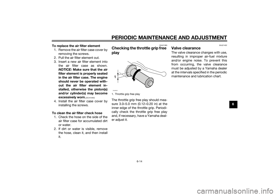
EAU21385
Checking the throttle grip free
playThe throttle grip free play should mea-
sure 3.0–5.0 mm (0.12–0.20 in) at the
inner edge of the throttle grip. Periodi-
cally check the throttle grip free play
and, if necessary, have a Yamaha deal-
er adjust it.
EAU21402
Valve clearanceThe valve clearance changes with use,
resulting in improper air-fuel mixture
and/or engine noise. To prevent this
from occurring, the valve clearance
must be adjusted by a Yamaha dealer
at the intervals specified in the periodic
maintenance and lubrication chart.
1. Throttle grip free play1ZAUM0051
U1GBE0E0.book Page 14 Wednesday, June 26, 2013 4:04 PM
Page 50 of 78
PERIODIC MAINTENANCE AND ADJUSTMENT
6-15
6
EAU21877
TiresTires are the only contact between the
vehicle and the road. Safety in all con-
ditions of riding depends on a relatively
small area of road contact. Therefore, it
is essential to maintain the tires in good
condition at all times and replace them
at the appropriate time with the speci-
fied tires.
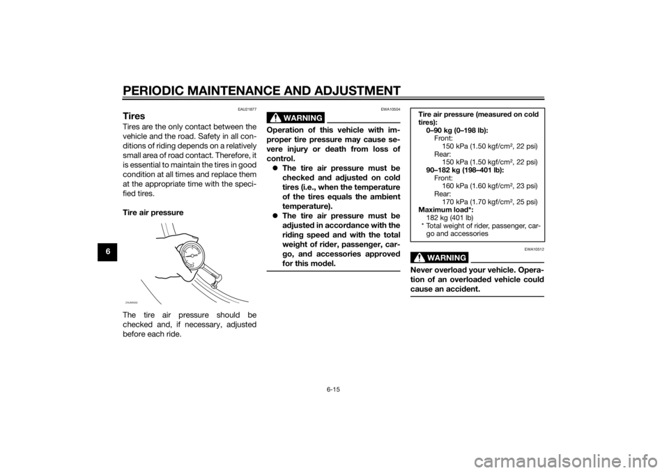
Tire air pressure
The tire air pressure should be
checked and, if necessary, adjusted
before each ride.
WARNING
EWA10504
Operation of this vehicle with im-
proper tire pressure may cause se-
vere injury or death from loss of
control.
The tire air pressure must be
checked and adjusted on cold
tires (i.e., when the temperature
of the tires equals the ambient
temperature).
The tire air pressure must be
adjusted in accordance with the
riding speed and with the total
weight of rider, passenger, car-
go, and accessories approved
for this model.
WARNING
EWA10512
Never overload your vehicle. Opera-
tion of an overloaded vehicle could
cause an accident.
ZAUM0053
Tire air pressure (measured on cold
tires):
0–90 kg (0–198 lb):
Front:
150 kPa (1.50 kgf/cm², 22 psi)
Rear:
150 kPa (1.50 kgf/cm², 22 psi)
90–182 kg (198–401 lb):
Front:
160 kPa (1.60 kgf/cm², 23 psi)
Rear:
170 kPa (1.70 kgf/cm², 25 psi)
Maximum load*:
182 kg (401 lb)
* Total weight of rider, passenger, car-
go and accessories
U1GBE0E0.book Page 15 Wednesday, June 26, 2013 4:04 PM