YAMAHA BANSHEE 350 2005 Owners Manual
Manufacturer: YAMAHA, Model Year: 2005, Model line: BANSHEE 350, Model: YAMAHA BANSHEE 350 2005Pages: 402, PDF Size: 4.93 MB
Page 301 of 402
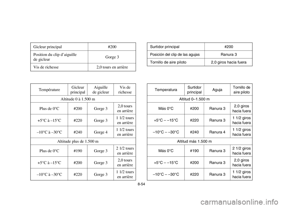
Ajustes estandar
Cuadro de ajustes de los carburadores
8-54
Réglage standard
Tableau de réglage du carburateur
Surtidor principal #200
Posición del clip de las agujasRanura 3
Tornillo de aire piloto 2,0 giros hacia fuera
Gicleur principal #200
Position du clip d’aiguille
de gicleurGorge 3
Vis de richesse 2,0 tours en arrière
TemperaturaSurtidor
AgujaTornillo deprincipalaire piloto
Altitud 0–1.500 m
Más 0°C #200 Ranura 32,0 giros
hacia fuera
+5°C – –15°C #220 Ranura 31 1/2 giroshacia fuera
–10°C – –30°C #240 Ranura 41 1/2 giroshacia fuera
Altitud más 1.500 m
Más 0°C #190 Ranura 32 1/2 giros
hacia fuera
+5°C – –15°C #200 Ranura 32,0 giroshacia fuera
–10°C – –30°C #220 Ranura 31 1/2 giroshacia fuera
TempératureGicleur Aiguille Vis de
principal de gicleur richesse
Altitude 0 à 1.500 m
Plus de 0°C #200 Gorge 32,0 tours
en arrière
+5°C à –15°C #220 Gorge 31 1/2 tours
en arrière
–10°C à –30°C #240 Gorge 41 1/2 tours
en arrière
Altitude plus de 1.500 m
Plus de 0°C #190 Gorge 32 1/2 tours
en arrière
+5°C à –15°C #200 Gorge 32,0 tours
en arrière
–10°C à –30°C #220 Gorge 31 1/2 tours
en arrière
5FK-9-66-05 12/3/04 7:54 PM Page 55
Page 302 of 402
8-55
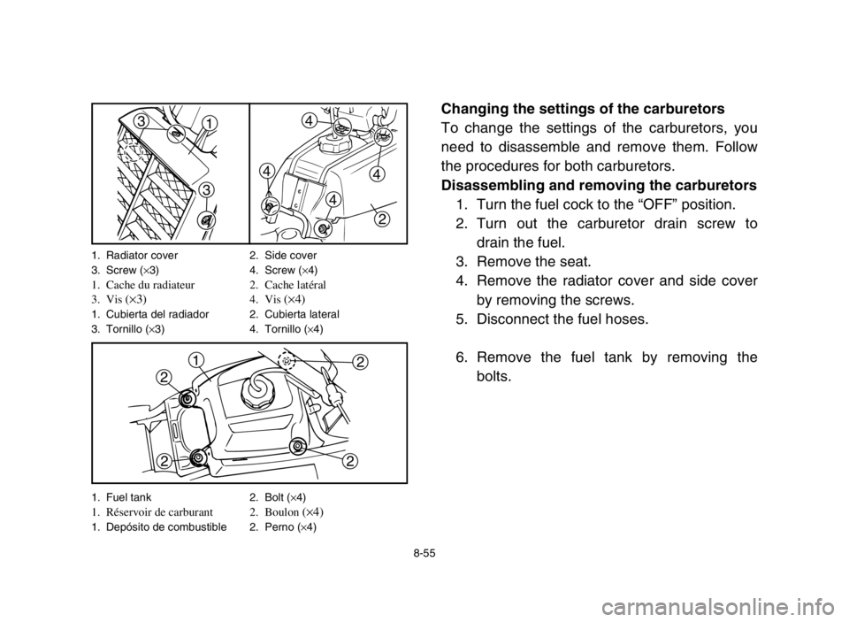
Changing the settings of the carburetors
To change the settings of the carburetors, you
need to disassemble and remove them. Follow
the procedures for both carburetors.
Disassembling and removing the carburetors
1. Turn the fuel cock to the “OFF” position.
2. Turn out the carburetor drain screw to
drain the fuel.
3. Remove the seat.
4. Remove the radiator cover and side cover
by removing the screws.
5. Disconnect the fuel hoses.
6. Remove the fuel tank by removing the
bolts.13
3
2 4
4
4
4
1
2
2 2
2
1. Radiator cover 2. Side cover
3. Screw (×3) 4. Screw (×4)
1. Cache du radiateur 2. Cache latéral
3. Vis (×3)4. Vis (×4)1. Cubierta del radiador 2. Cubierta lateral
3. Tornillo (×3) 4. Tornillo (×4)
1. Fuel tank 2. Bolt (×4)
1. Réservoir de carburant 2. Boulon (×4)
1. Depósito de combustible 2. Perno (×4)
5FK-9-66-05 12/3/04 7:54 PM Page 56
Page 303 of 402

Modificación de los ajustes de los carbura-
dores
Para cambiar los ajustes de los carburadores, es
necesario desmontarlos y extraerlos. Siga los pro-
cedimientos siguientes para ambos carburadores.
Desmontaje y extracción de los carburadores
1. Gire el grifo de combustible a la posición
“OFF” (cerrado).
2. Desenrosque el tornillo de drenaje del car-
burador para drenar el combustible.
3. Desmonte el sillín.
4. Extraiga la cubierta del radiador y la
cubierta lateral quitando los tornillos.
5. Desconecte los tubos de combustible.
6. Extraiga el depósito de combustible quitan-
do los pernos.
8-56
Modification du réglage des carburateurs
La dépose et le démontage des carburateurs sont
nécessaires afin de pouvoir procéder à leur
réglage. Suivre le procédé pour chacun des deux
carburateurs.
Dépose et démontage des carburateurs
1. Placer le robinet à carburant sur “OFF”.
2. Dévisser la vis de vidange du carburateur
afin de vidanger le carburant.
3. Déposer la selle.
4. Déposer le cache du radiateur et le cache
latéral après avoir retiré les vis.
5. Déconnecter les flexibles de carburant.
6. Déposer le réservoir de carburant après
avoir retiré les boulons.
5FK-9-66-05 12/3/04 7:54 PM Page 57
Page 304 of 402
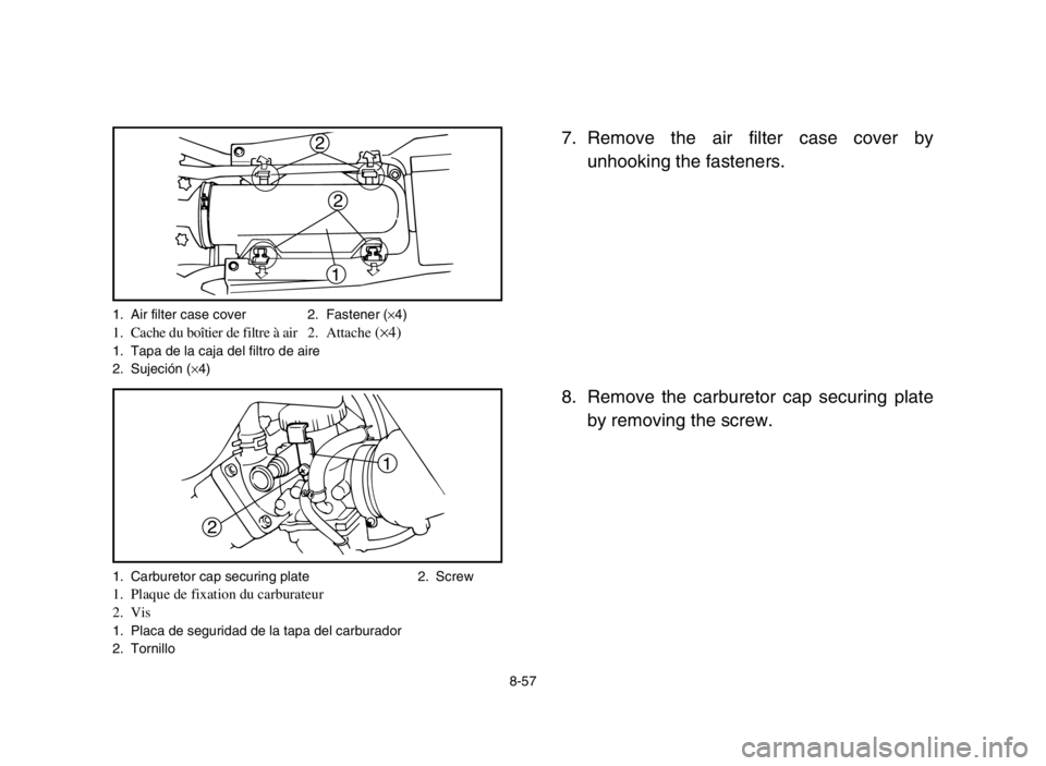
1
2
1. Air filter case cover 2. Fastener (×4)1. Cache du boîtier de filtre à air 2. Attache (×4)1. Tapa de la caja del filtro de aire
2. Sujeción (×4)
1. Carburetor cap securing plate 2. Screw
1. Plaque de fixation du carburateur
2. Vis
1. Placa de seguridad de la tapa del carburador
2. Tornillo
8-57
7. Remove the air filter case cover by
unhooking the fasteners.
8. Remove the carburetor cap securing plate
by removing the screw.
1
2
2
5FK-9-66-05 12/3/04 7:54 PM Page 58
Page 305 of 402

7. Quite la tapa de la caja del filtro de aire
desenganchando los fijadores.
8. Extraiga la placa de seguridad de la tapa
del carburador quitando los tornillos.
8-58
7. Retirer le couvercle du boîtier de filtre à air
en décrochant les attaches.
8. Déposer la plaque de fixation du carbura-
teur après avoir retiré sa vis.
5FK-9-66-05 12/3/04 7:54 PM Page 59
Page 306 of 402
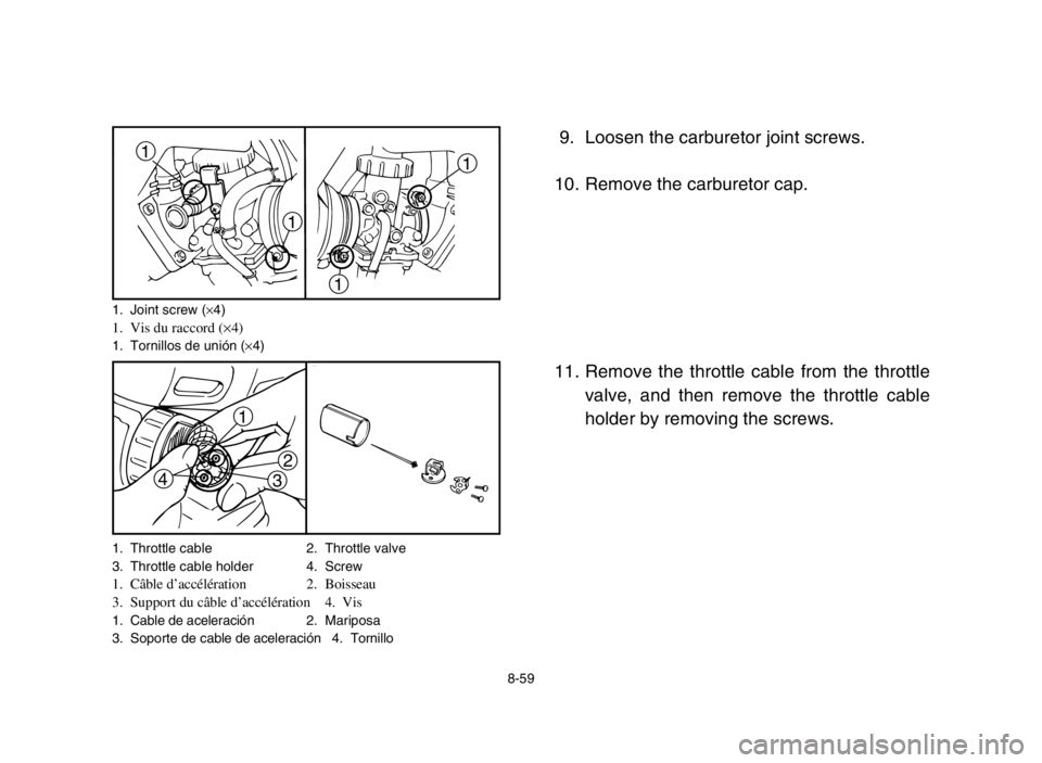
1. Throttle cable 2. Throttle valve
3. Throttle cable holder 4. Screw
1. Câble d’accélération 2. Boisseau
3. Support du câble d’accélération 4. Vis
1. Cable de aceleración 2. Mariposa
3. Soporte de cable de aceleración 4. Tornillo
8-59
9. Loosen the carburetor joint screws.
10. Remove the carburetor cap.
11. Remove the throttle cable from the throttle
valve, and then remove the throttle cable
holder by removing the screws.1
1
11
1
2
3
4
1. Joint screw (×4)1. Vis du raccord (×4)1. Tornillos de unión (×4)
5FK-9-66-05 12/3/04 7:54 PM Page 60
Page 307 of 402

9. Afloje los tornillos de unión del carburador.
10. Extraiga la tapa del carburador.
11. Extraiga los cables de aceleración de las
mariposas de gases y a continuación el
soporte de cables del acelerador quitando
los tornillos.
8-60
9. Desserrer les vis du raccord de carburateur.
10. Retirer le chapeau du carburateur.
11. Retirer le câble des gaz du papillon d’accé-
lération, puis retirer le support du câble des
gaz après avoir retiré les vis.
5FK-9-66-05 12/3/04 7:54 PM Page 61
Page 308 of 402
8-61
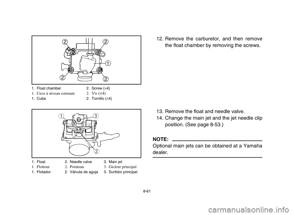
12. Remove the carburetor, and then remove
the float chamber by removing the screws.
13. Remove the float and needle valve.
14. Change the main jet and the jet needle clip
position. (See page 8-53.)
NOTE:
Optional main jets can be obtained at a Yamaha
dealer.
1
22
22
q
w e
1. Float chamber 2. Screw (×4)1. Cuve à niveau constant 2. Vis (×4)1. Cuba 2. Tornillo (×4)
1. Float 2. Needle valve 3. Main jet
1. Flotteur 2. Pointeau 3. Gicleur principal1. Flotador 2. Válvula de aguja 3. Surtidor principal
5FK-9-66-05 12/3/04 7:54 PM Page 62
Page 309 of 402

12. Extraiga el carburador y luego extraiga la
cámara del flotador quitando los tornillos.
13. Extraiga los flotadores y las válvulas de
aguja.
14. Cambie las posiciones de los surtidores
principales y de los retenedores de las
agujas (vea la página 8-54).
NOTA:
Se pueden obtener surtidores principales opcio-
nales en un concesionario Yamaha.
8-62
12. Déposer le carburateur, puis retirer la cuve
à niveau constant après avoir enlevé les vis.
13. Retirer le flotteur et le pointeau.
14. Changer le gicleur principal et changer la
position de l’agrafe d’accrochage de
l’aiguille. (Voir page 8-54.)
N.B.:
Des gicleurs principaux optionnels sont dispo-
nibles chez les concessionnaires Yamaha.
5FK-9-66-05 12/3/04 7:54 PM Page 63
Page 310 of 402
8-63
Assembling and installing the carburetors
Assemble and install both carburetors by the fol-
lowing steps.
1. Install the needle valve and float.
2. Install the float chamber by installing the
screws.
3. Install the carburetor and tighten the joint
screws.
4. Assemble the throttle valve.
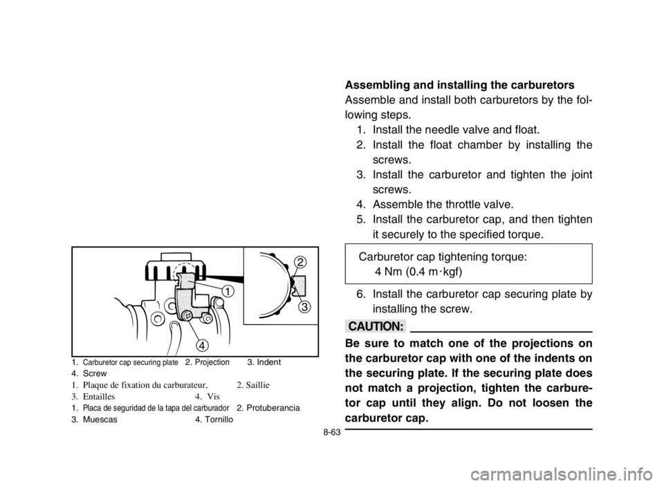
5. Install the carburetor cap, and then tighten
it securely to the specified torque.
6. Install the carburetor cap securing plate by
installing the screw.
cC
Be sure to match one of the projections on
the carburetor cap with one of the indents on
the securing plate. If the securing plate does
not match a projection, tighten the carbure-
tor cap until they align. Do not loosen the
carburetor cap.
12
3
4
1.Carburetor cap securing plate2. Projection3. Indent
4. Screw
1. Plaque de fixation du carburateur, 2. Saillie
3. Entailles 4. Vis
1.Placa de seguridad de la tapa del carburador2. Protuberancia
3. Muescas 4. Tornillo
Carburetor cap tightening torque:
4 Nm (0.4 m0kgf)
5FK-9-66-05 12/3/04 7:54 PM Page 64