clock YAMAHA CYGNUS 125 2006 Owners Manual
[x] Cancel search | Manufacturer: YAMAHA, Model Year: 2006, Model line: CYGNUS 125, Model: YAMAHA CYGNUS 125 2006Pages: 44, PDF Size: 8.15 MB
Page 14 of 44

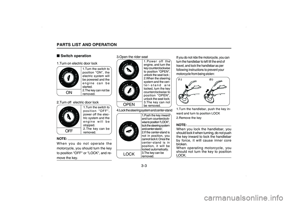
1.Turn the switch to
position "ON", the
electric system will
be powered and the
engine can be
started.
2.The key can not be
removed.
1.Turn the switch to
position "OFF",
power off the elec-
tric system and the
engine will be
stopped.
2.The key can be
removed.
ON
OFF
LOCK
1.Power off the
engine, and turn the
key counterclockwise
to position "OPEN",
unlock the seat lock ;2.When the steering
system and the cen-
ter-stand are
locked, turn the key
counterclockwise to
position "OPEN",
unlock the seat lock;
3.The key can not
be removed.
1.Turn on electric door lock
2.Turn off electric door lock
4.
Lock the steering system and center-stand3.Open the rider seat
NOTE:
When you do not operate the
motorcycle, you should turn the key
to position "OFF" or "LOCK", and re-move the key.
1.Turn the handlebar, push the key in-
ward and turn to position LOCK
2.Remove the key(1.)If you do not ride the motorcycle, you can
turn the handlebar to left till the end of
travel, and lock the handlebar as per
following instructions to prevent your
motorcycle from being stolen:NOTE: When you lock the handlebar, you
should lock it when turning, do not push
the key inward to lock the handlebar
by force, it will cause inner core
broken.
When operating motorcycle, you
should not turn the key to positionLOCK.
OPEN
■ ■■ ■
■Switch operation
1.Push the key inward
and turn counterclock-
wise to position "LOCK",
lock the steering system
and center-stand ;2.If the center-stand is
not in position, you
cannot lock it. Once the
center-stand is in
position, it will be
locked automatically.
3.The key can be
removed.
PARTS LIST AND OPERATION
(2.)
3-3
Page 16 of 44

WARNING
Do not exceed the load limit of 3 kgfor the front storage compartment.
■ ■■ ■
■Storage compartmentThe storage compartment locates
under seat, which can hold a full-cov-
ered helmet. When storing helmet,
place it upright, and the front side
should face the motorcycle head
(shown in the drawing above).
PARTS LIST AND OPERATION■ ■■ ■
■Fuel tank capThe fuel tank cap locates under the
rider seat, open the seat and you can
see the cap.
1. If you wish to remove the fuel tank
cap, turn it counterclockwise.
2. If you wish to fasten the fuel tank
cap, table the flange in the cap to the
groove in the fuel tank, and turn
clockwise.
3. Gasoline
Make sure that there is enough fuel in
the tank; fill the tank till the fuel reaches
the bottom of filler tube as per
illustration.
Fuel tank capacity: 5.4L
■ ■■ ■
■Front storage compartment
3-5
Fuel tank cap
2
1
Page 35 of 44

CAUTION:
Before the motorcycle leaving factory,
we have already set the carburetor to
the standard position. Change the set-
ting at random will affect the engine
performance and increase the dis-charge of exhaust gas.■ ■■ ■
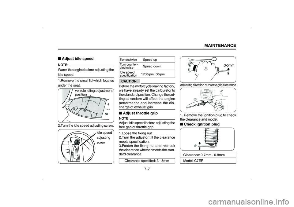
■Adjust throttle gripNOTE: Adjust idle speed before adjusting thefree gap of throttle grip.
1.Loose the fixing nut.
2.Turn the adjustor till the clearance
meets specification.
3.Fasten the fixing nut and recheck
the clearance whether meets the stan-
dard clearance. idle speed
adjusting
screw
MAINTENANCE
■ ■■ ■
■Adjust idle speedNOTE: Warm the engine before adjusting theidle speed.
1.Remove the small lid which locates
under the seat.
2.Turn the idle speed adjusting screw.
Turn clockwiseTurn counter-
clockwise
Idle speed
specificationSpeed up
Speed down
1700rpm 50rpm
Clearance: 0.7mm - 0.8mm
Model: C7ER
Clearance specified: 3 - 5mm
Adjusting direction of throttle grip clearance1. Remove the ignition plug to check
the clearance and model.■ ■■ ■
■Check ignition plug
7-7
vehicle idling adjustment
position3-5mm