engine YAMAHA EX 2022 Owner's Manual
[x] Cancel search | Manufacturer: YAMAHA, Model Year: 2022, Model line: EX, Model: YAMAHA EX 2022Pages: 100, PDF Size: 4.74 MB
Page 38 of 100
Instrument operation
31
EJU44571
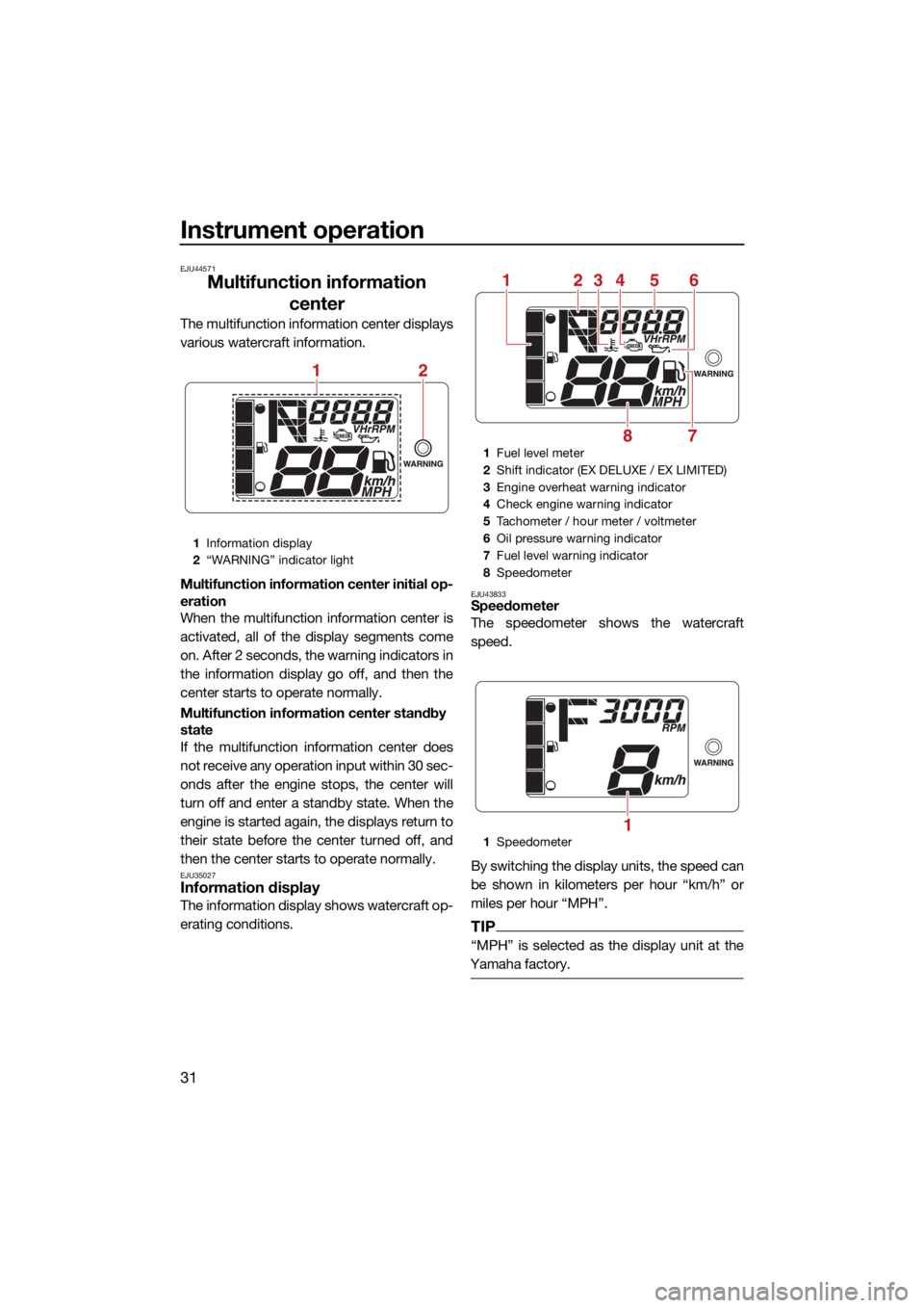
Multifunction information center
The multifunction information center displays
various watercraft information.
Multifunction information center initial op-
eration
When the multifunction information center is
activated, all of the display segments come
on. After 2 seconds, the warning indicators in
the information display go off, and then the
center starts to operate normally.
Multifunction information center standby
state
If the multifunction information center does
not receive any operation input within 30 sec-
onds after the engine stops, the center will
turn off and enter a standby state. When the
engine is started again, the displays return to
their state before the center turned off, and
then the center starts to operate normally.
EJU35027Information display
The information display shows watercraft op-
erating conditions.
EJU43833Speedometer
The speedometer shows the watercraft
speed.
By switching the display units, the speed can
be shown in kilometers per hour “km/h” or
miles per hour “MPH”.
TIP
“MPH” is selected as the display unit at the
Yamaha factory.
1 Information display
2 “WARNING” indicator light
12
1Fuel level meter
2 Shift indicator (EX DELUXE / EX LIMITED)
3 Engine overheat warning indicator
4 Check engine warning indicator
5 Tachometer / hour meter / voltmeter
6 Oil pressure warning indicator
7 Fuel level warning indicator
8 Speedometer
1 Speedometer
251346
78
1
UF3Y75E0.book Page 31 Tuesday, July 27, 2021 2:27 PM
Page 39 of 100
Instrument operation
32
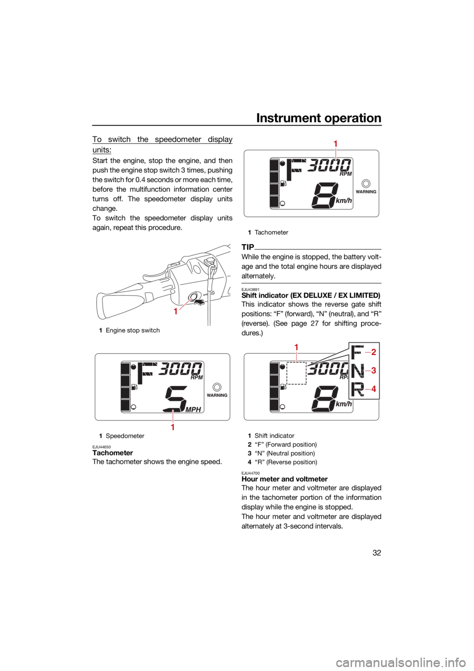
To switch the speedometer display
units:
Start the engine, stop the engine, and then
push the engine stop switch 3 times, pushing
the switch for 0.4 seconds or more each time,
before the multifunction information center
turns off. The speedometer display units
change.
To switch the speedometer display units
again, repeat this procedure.
EJU44650Tachometer
The tachometer shows the engine speed.
TIP
While the engine is stopped, the battery volt-
age and the total engine hours are displayed
alternately.
EJU43891Shift indicator (EX DELUXE / EX LIMITED)
This indicator shows the reverse gate shift
positions: “F” (forward), “N” (neutral), and “R”
(reverse). (See page 27 for shifting proce-
dures.)
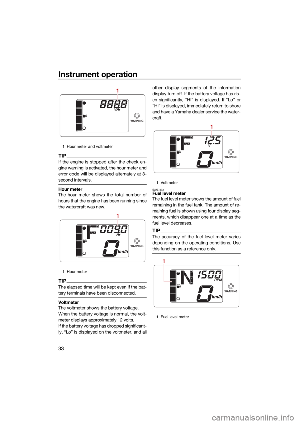
EJU44700Hour meter and voltmeter
The hour meter and voltmeter are displayed
in the tachometer portion of the information
display while the engine is stopped.
The hour meter and voltmeter are displayed
alternately at 3-second intervals.
1 Engine stop switch
1 Speedometer
1
1
1Tachometer
1 Shift indicator
2 “F” (Forward position)
3 “N” (Neutral position)
4 “R” (Reverse position)
1
12
3
4
UF3Y75E0.book Page 32 Tuesday, July 27, 2021 2:27 PM
Page 40 of 100
Instrument operation
33
TIP
If the engine is stopped after the check en-
gine warning is activated, the hour meter and
error code will be displayed alternately at 3-
second intervals.
Hour meter
The hour meter shows the total number of
hours that the engine has been running since
the watercraft was new.
TIP
The elapsed time will be kept even if the bat-
tery terminals have been disconnected.
Voltmeter
The voltmeter shows the battery voltage.
When the battery voltage is normal, the volt-
meter displays approximately 12 volts.
If the battery voltage has dropped significant-
ly, “Lo” is displayed on the voltmeter, and allother display segments of the information
display turn off. If the battery voltage has ris-
en significantly, “HI” is displayed. If “Lo” or
“HI” is displayed, immediately return to shore
and have a Yamaha dealer service the water-
craft.
EJU37272Fuel level meter
The fuel level meter shows the amount of fuel
remaining in the fuel tank. The amount of re-
maining fuel is shown using four display seg-
ments, which disappear one at a time as the
fuel level decreases.
TIP
The accuracy of the fuel level meter varies
depending on the operating conditions. Use
this function as a reference only.
1
Hour meter and voltmeter
1 Hour meter
1
1
1Vo l t m et e r
1 Fuel level meter
1
1
UF3Y75E0.book Page 33 Tuesday, July 27, 2021 2:27 PM
Page 41 of 100
Instrument operation
34
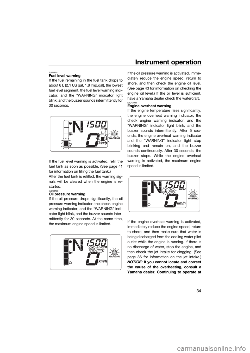
EJU44711Fuel level warning
If the fuel remaining in the fuel tank drops to
about 8 L (2.1 US gal, 1.8 Imp.gal), the lowest
fuel level segment, the fuel level warning indi-
cator, and the “WARNING” indicator light
blink, and the buzzer sounds intermittently for
30 seconds.
If the fuel level warning is activated, refill the
fuel tank as soon as possible. (See page 41
for information on filling the fuel tank.)
After the fuel tank is refilled, the warning sig-
nals will be cleared when the engine is re-
started.
EJU43720Oil pressure warning
If the oil pressure drops significantly, the oil
pressure warning indicator, the check engine
warning indicator, and the “WARNING” indi-
cator light blink, and the buzzer sounds inter-
mittently for 30 seconds. At the same time,
the maximum engine speed is limited.If the oil pressure warning is activated, imme-
diately reduce the engine speed, return to
shore, and then check the engine oil level.
(See page 43 for information on checking the
engine oil level.) If the oil level is sufficient,
have a Yamaha dealer check the watercraft.
EJU43901Engine overheat warning
If the engine temperature rises significantly,
the engine overheat warning indicator, the
check engine warning indicator, and the
“WARNING” indicator light blink, and the
buzzer sounds intermittently. After 5 sec-
onds, the engine overheat warning indicator
and the “WARNING” indicator light stop
blinking and remain on, and the buzzer
sounds continuously. After 30 seconds, the
buzzer stops. While the engine overheat
warning is activated, the maximum engine
speed is limited.
If the engine overheat warning is activated,
immediately reduce the engine speed, return
to shore, and then make sure that water is
being discharged from the cooling water pilot
outlet while the engine is running. If there is
no discharge of water, stop the engine, and
then check the jet intake for clogging. (See
page 86 for information on the jet intake.)
NOTICE: If you cannot locate and correct
the cause of the overheating, consult a
Yamaha dealer. Continuing to operate at
UF3Y75E0.book Page 34 Tuesday, July 27, 2021 2:27 PM
Page 42 of 100
![YAMAHA EX 2022 Owners Manual Instrument operation
35
higher speeds could result in severe en-
gine damage.
[ECJ00042]
EJU44690
Check engine warning
If a sensor malfunction or a short circuit is de-
tected, the check engine warni YAMAHA EX 2022 Owners Manual Instrument operation
35
higher speeds could result in severe en-
gine damage.
[ECJ00042]
EJU44690
Check engine warning
If a sensor malfunction or a short circuit is de-
tected, the check engine warni](/img/51/49467/w960_49467-41.png)
Instrument operation
35
higher speeds could result in severe en-
gine damage.
[ECJ00042]
EJU44690
Check engine warning
If a sensor malfunction or a short circuit is de-
tected, the check engine warning indicator
and the “WARNING” indicator light blink, and
the buzzer sounds intermittently for 30 sec-
onds.
If the engine is stopped after the check en-
gine warning is activated, the tachometer
portion of the information display will show
the hour meter and error code alternately at
3-second intervals. If the check engine warning is activated, im-
mediately reduce the engine speed, return to
shore, and have a Yamaha dealer check the
engine.
1
Error code
1
UF3Y75E0.book Page 35 Tuesday, July 27, 2021 2:27 PM
Page 43 of 100
Equipment operation
36
EJU40336
EquipmentEJU44600Seat
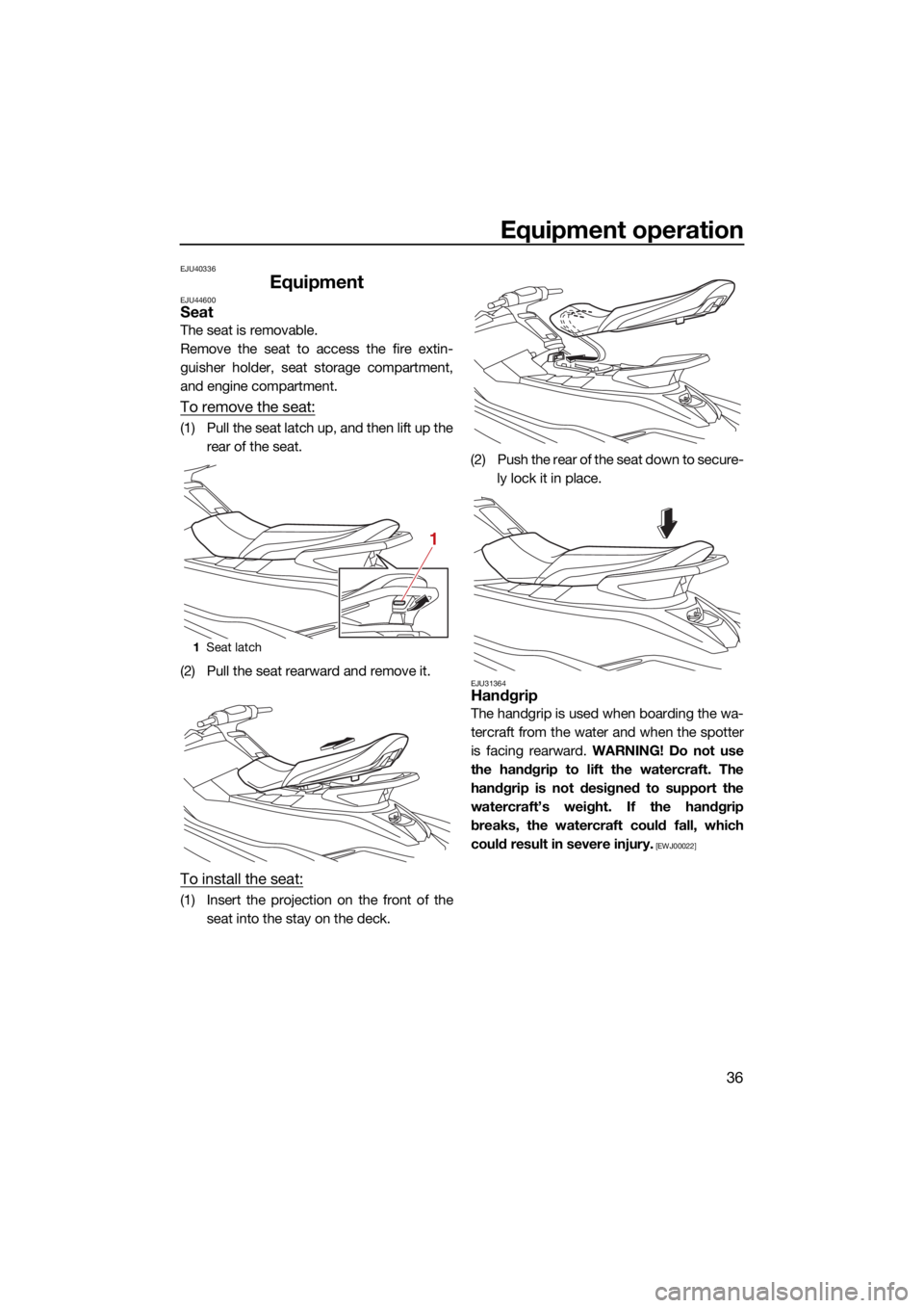
The seat is removable.
Remove the seat to access the fire extin-
guisher holder, seat storage compartment,
and engine compartment.
To remove the seat:
(1) Pull the seat latch up, and then lift up therear of the seat.
(2) Pull the seat rearward and remove it.
To install the seat:
(1) Insert the projection on the front of the seat into the stay on the deck. (2) Push the rear of the seat down to secure-
ly lock it in place.
EJU31364Handgrip
The handgrip is used when boarding the wa-
tercraft from the water and when the spotter
is facing rearward. WARNING! Do not use
the handgrip to lift the watercraft. The
handgrip is not designed to support the
watercraft’s weight. If the handgrip
breaks, the watercraft could fall, which
could result in severe injury.
[EWJ00022]
1 Seat latch
1
UF3Y75E0.book Page 36 Tuesday, July 27, 2021 2:27 PM
Page 48 of 100
Operation and handling requirements
41
EJU31823
Fuel requirementsEJU44880FuelEWJ00283
Gasoline and gasoline vapors are ex-
tremely flammable. To avoid fires and
explosions and to reduce the risk of in-
jury when refueling, follow these in-
structions.
Gasoline is poisonous and can cause in-
jury or death. Handle gasoline with care.
Never siphon gasoline by mouth. If you
should swallow some gasoline, inhale a
lot of gasoline vapor, or get some gaso-
line in your eyes, see your doctor imme-
diately. If gasoline spills on your skin,
wash with soap and water. If gasoline
spills on your clothing, change your
clothes.
ECJ00322
Do not use leaded gasoline. Leaded
gasoline can seriously damage the en-
gine.
Avoid getting water and contaminants in
the fuel tank. Contaminated fuel can
cause poor performance and engine
damage. Use only fresh gasoline that
has been stored in clean containers.
TIP
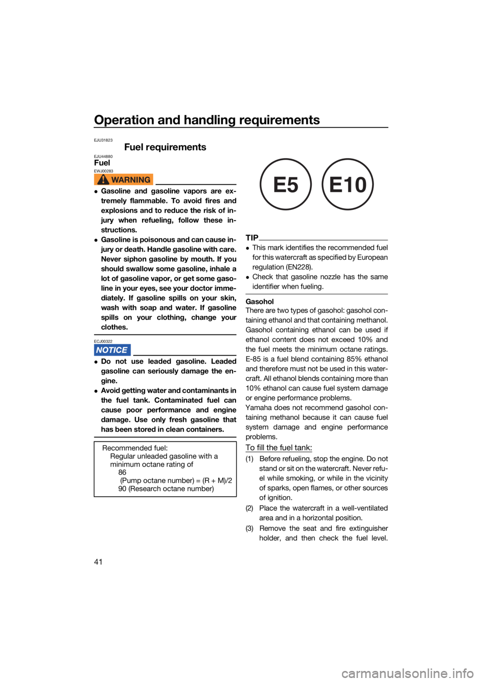
This mark identifies the recommended fuel
for this watercraft as specified by European
regulation (EN228).
Check that gasoline nozzle has the same
identifier when fueling.
Gasohol
There are two types of gasohol: gasohol con-
taining ethanol and that containing methanol.
Gasohol containing ethanol can be used if
ethanol content does not exceed 10% and
the fuel meets the minimum octane ratings.
E-85 is a fuel blend containing 85% ethanol
and therefore must not be used in this water-
craft. All ethanol blends containing more than
10% ethanol can cause fuel system damage
or engine performance problems.
Yamaha does not recommend gasohol con- taining methanol because it can cause fuel
system damage and engine performance
problems.
To fill the fuel tank:
(1) Before refueling, stop the engine. Do not stand or sit on the watercraft. Never refu-
el while smoking, or while in the vicinity
of sparks, open flames, or other sources
of ignition.
(2) Place the watercraft in a well-ventilated area and in a horizontal position.
(3) Remove the seat and fire extinguisher holder, and then check the fuel level.
Recommended fuel:
Regular unleaded gasoline with a
minimum octane rating of86
(Pump octane number) = (R + M)/2
90 (Research octane number)
E5E10
UF3Y75E0.book Page 41 Tuesday, July 27, 2021 2:27 PM
Page 49 of 100
Operation and handling requirements
42
(See page 36 for seat removal and instal-
lation procedures and page 40 for infor-
mation on the fire extinguisher holder.)
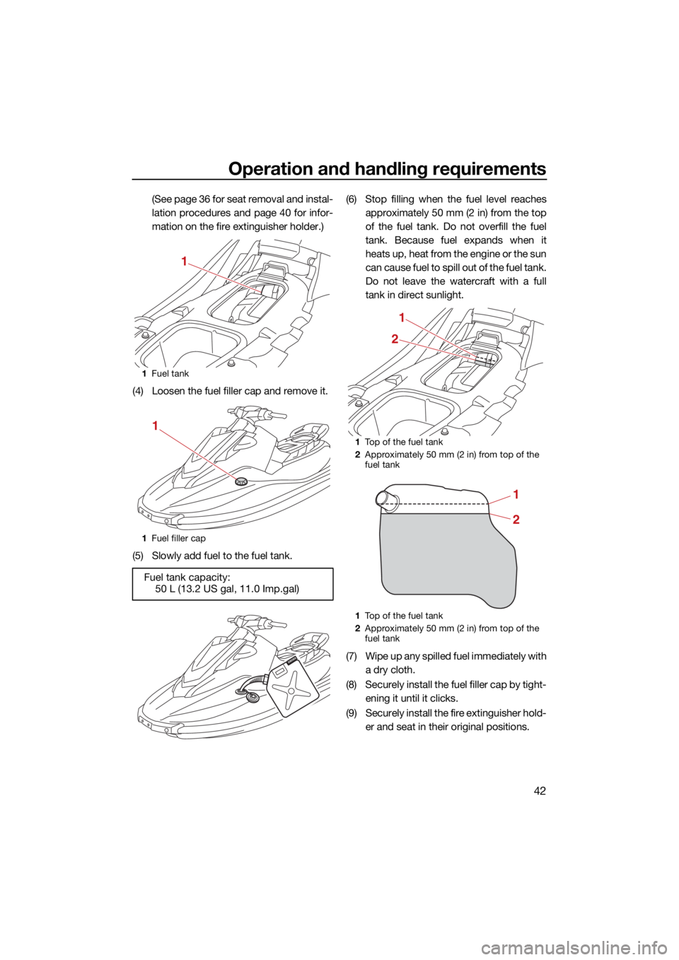
(4) Loosen the fuel filler cap and remove it.
(5) Slowly add fuel to the fuel tank. (6) Stop filling when the fuel level reaches
approximately 50 mm (2 in) from the top
of the fuel tank. Do not overfill the fuel
tank. Because fuel expands when it
heats up, heat from the engine or the sun
can cause fuel to spill out of the fuel tank.
Do not leave the watercraft with a full
tank in direct sunlight.
(7) Wipe up any spilled fuel immediately with a dry cloth.
(8) Securely install the fuel filler cap by tight- ening it until it clicks.
(9) Securely install the fire extinguisher hold- er and seat in their original positions.
1Fuel tank
1 Fuel filler cap
Fuel tank capacity:
50 L (13.2 US gal, 11.0 Imp.gal)
1
1
1Top of the fuel tank
2 Approximately 50 mm (2 in) from top of the
fuel tank
1 Top of the fuel tank
2 Approximately 50 mm (2 in) from top of the
fuel tank
21
1
2
UF3Y75E0.book Page 42 Tuesday, July 27, 2021 2:27 PM
Page 50 of 100
Operation and handling requirements
43
EJU40291
Engine oil requirementsEJU44531Engine oilECJ00282
Use only 4-stroke engine oil. Usage of 2-
stroke engine oil could result in severe en-
gine damage.
Why Yamalube
YAMALUBE oil is a Genuine YAMAHA Part
born of the engineers’ passion and belief that
engine oil is an important liquid engine com-
ponent. We form teams of specialists in the
fields of mechanical engineering, chemistry,
electronics and track testing, and have them
develop the engine together with the oil it will
use. Yamalube oils take full advantage of the
base oil’s qualities and blend in the ideal bal-
ance of additives to make sure the final oil
clears our performance standards. Thus,
Yamalube mineral, semisynthetic and syn- thetic oils have their own distinct characters
and value. Yamaha’s experience gained over
many years of research and development
into oil since the 1960’s helps make
Yamalube the best choice for your Yamaha engine. Checking the engine oil level
EWJ00341
Engine oil is extremely hot immediately af-
ter the engine is turned off. Coming in con-
tact with or getting any engine oil on your
clothes could result in burns.
ECJ00392
Do not run the engine with too much or
not enough oil in the oil tank, otherwise
the engine could be damaged.
Make sure that debris and water do not
enter the oil tank filler hole. Debris and
water in the engine oil can cause serious
engine damage.
TIP
When checking the engine oil level on land,
the engine must be running while water is
being supplied to the cooling water pas-
sages. (See “Flushing the cooling water
passages” on page 71 for information on
supplying water.)
When checking the engine oil level on wa-
ter, moor the watercraft so that it will not
drift away.
To check the engine oil level:
(1) With the engine stopped, place the wa-
tercraft in a precisely level position on
land or launch the watercraft.
(2) Look in all directions, and then start the engine. (See page 58 for information on
starting the engine.)
(3) Run the engine at idling speed for 6 min- utes or more. Run the engine an addi-
tional 5 minutes if the ambient
temperature is 20 °C (68 °F) or less.
(4) Stop the engine.
Recommended engine oil:
YAMALUBE 4W or 4-stroke motor oil
Recommended engine oil type: SAE 10W-30, 10W-40, 20W-40,
20W-50
Recommended engine oil grade: API SG, SH, SJ, SL
UF3Y75E0.book Page 43 Tuesday, July 27, 2021 2:27 PM
Page 51 of 100
Operation and handling requirements
44
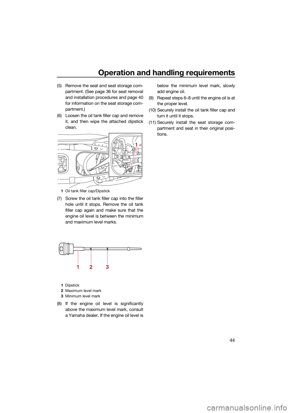
(5) Remove the seat and seat storage com-partment. (See page 36 for seat removal
and installation procedures and page 40
for information on the seat storage com-
partment.)
(6) Loosen the oil tank filler cap and remove it, and then wipe the attached dipstick
clean.
(7) Screw the oil tank filler cap into the filler hole until it stops. Remove the oil tank
filler cap again and make sure that the
engine oil level is between the minimum
and maximum level marks.
(8) If the engine oil level is significantly above the maximum level mark, consult
a Yamaha dealer. If the engine oil level is below the minimum level mark, slowly
add engine oil.
(9) Repeat steps 6–8 until the engine oil is at the proper level.
(10) Securely install the oil tank filler cap and turn it until it stops.
(11) Securely install the seat storage com- partment and seat in their original posi-
tions.
1Oil tank filler cap/Dipstick
1 Dipstick
2 Maximum level mark
3 Minimum level mark
1
213
UF3Y75E0.book Page 44 Tuesday, July 27, 2021 2:27 PM