horn YAMAHA GRIZZLY 250 2010 Owners Manual
[x] Cancel search | Manufacturer: YAMAHA, Model Year: 2010, Model line: GRIZZLY 250, Model: YAMAHA GRIZZLY 250 2010Pages: 140, PDF Size: 4.79 MB
Page 25 of 140

3-2
3
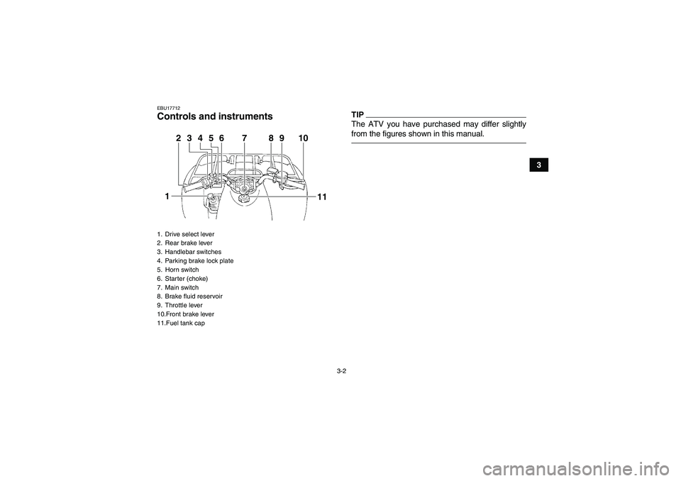
EBU17712Controls and instruments
TIPThe ATV you have purchased may differ slightly
from the figures shown in this manual.
1. Drive select lever
2. Rear brake lever
3. Handlebar switches
4. Parking brake lock plate
5. Horn switch
6. Starter (choke)
7. Main switch
8. Brake fluid reservoir
9. Throttle lever
10.Front brake lever
11.Fuel tank cap
2
1
3
4
5
6
7
9
8
10
11
U1P065E0.book Page 2 Monday, August 31, 2009 1:10 PM
Page 27 of 140

4-2
4
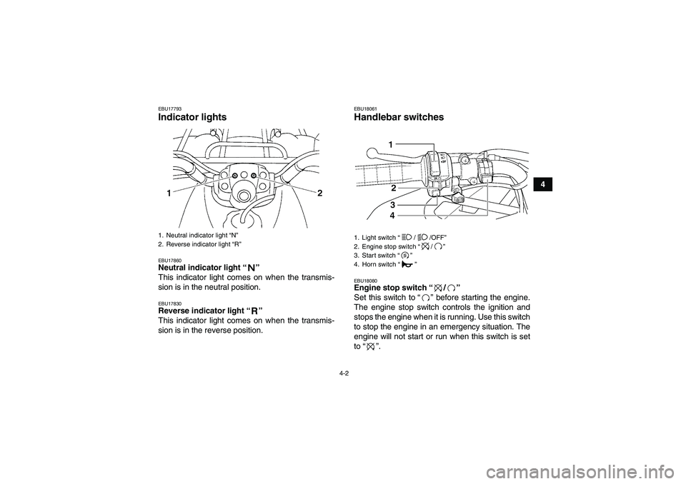
EBU17793Indicator lights EBU17860Neutral indicator light“”
This indicator light comes on when the transmis-
sion is in the neutral position.EBU17830Reverse indicator light“”
This indicator light comes on when the transmis-
sion is in the reverse position.
EBU18061Handlebar switches EBU18080Engine stop switch“/”
Set this switch to“” before starting the engine.
The engine stop switch controls the ignition and
stops the engine when it is running. Use this switch
to stop the engine in an emergency situation. The
engine will not start or run when this switch is set
to“”.
1. Neutral indicator light “N”
2. Reverse indicator light “R”
1. Light switch“//OFF”
2. Engine stop switch“/”
3. Start switch“”
4. Horn switch“”
U1P065E0.book Page 2 Monday, August 31, 2009 1:10 PM
Page 28 of 140

4-3
4
EBU18101Start switch“”
Push this switch to crank the engine with the start-
er. See the starting instructions on page 6-1 prior
to starting the engine.EBU18152Light switch“//OFF”
Set this switch to“” to turn on the low beams
and the taillight. Set the switch to“” to turn on
the high beams and the taillight. Set the switch to
“OFF” to turn off all the lights.NOTICEECB00041Do not use the headlights with the engine
turned off for an extended period of time, oth-
erwise the battery may discharge to the point
that the starter motor will not operate properly.
If this should happen, remove the battery and
recharge it. See page 8-38 for battery charging
information.EBU18170Horn switch“”
Press the switch to sound the horn.
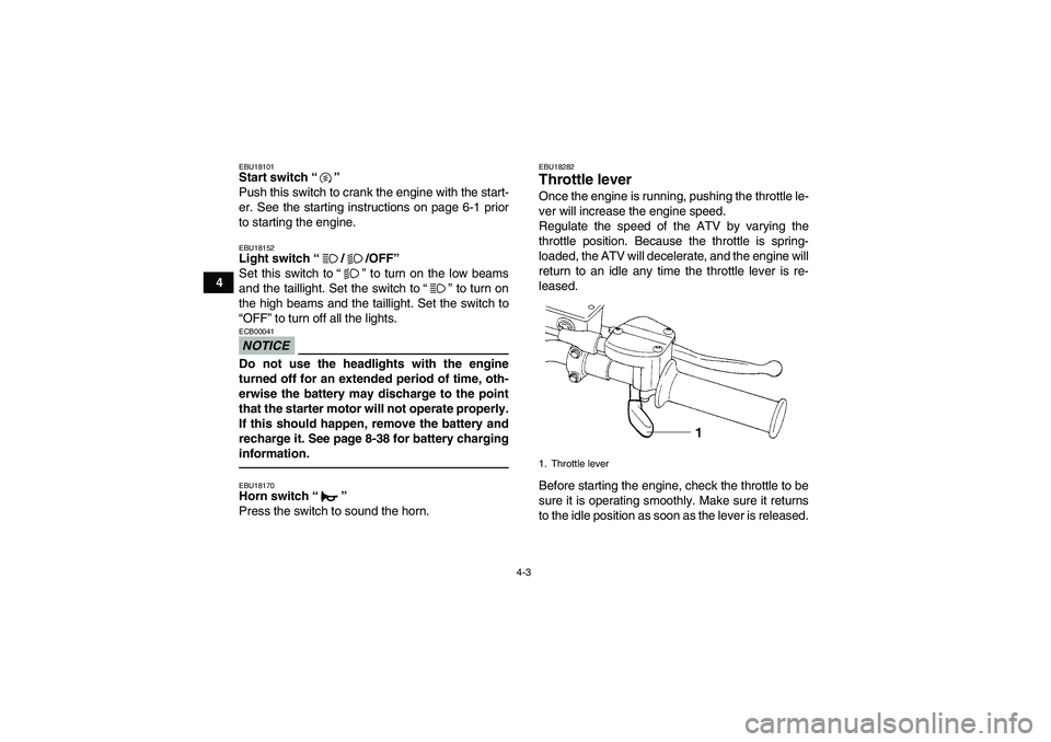
EBU18282Throttle lever Once the engine is running, pushing the throttle le-
ver will increase the engine speed.
Regulate the speed of the ATV by varying the
throttle position. Because the throttle is spring-
loaded, the ATV will decelerate, and the engine will
return to an idle any time the throttle lever is re-
leased.
Before starting the engine, check the throttle to be
sure it is operating smoothly. Make sure it returns
to the idle position as soon as the lever is released.1. Throttle lever
U1P065E0.book Page 3 Monday, August 31, 2009 1:10 PM
Page 137 of 140

INDEX
AAccessories and loading ................................................ 6-8
Air filter element, cleaning ............................................ 8-20BBattery ................................................................... 5-6, 8-38
Brake fluid, changing ................................................... 8-29
Brake fluid level, checking ........................................... 8-29
Brake lever free play, checking the front ...................... 8-30
Brake lever, front ............................................................ 4-4
Brake levers, checking and lubricating ........................ 8-35
Brake light switches ..................................................... 8-33
Brake pads and shoes, checking ................................. 8-27
Brake pedal and rear brake lever ................................... 4-5
Brake pedal, checking and lubricating ......................... 8-36
Brake pedal position, free play and brake lever free
play (rear), adjusting .................................................. 8-30
Brakes .......................................................................... 8-27
Brakes, front and rear .................................................... 5-3CCables, checking and lubricating ................................. 8-35
Carburetor, adjusting ................................................... 8-25
Carrier, front ................................................................. 4-13
Carrier, rear .................................................................. 4-13
Chassis fasteners .......................................................... 5-6
Cleaning ......................................................................... 9-1
Clutch free play, adjusting ............................................ 8-34DDrive select lever ........................................................... 4-7Drive select lever and driving in reverse ........................ 6-3
Drive select lever safety system cable, adjusting ........ 8-27
EEngine break-in .............................................................. 6-6
Engine, cold start ........................................................... 6-1
Engine idling speed ..................................................... 8-25
Engine oil ....................................................................... 5-3
Engine oil and oil filter element .................................... 8-11
Engine, starting a warm ................................................. 6-2
Engine stop switch ......................................................... 4-2FFinal gear oil ......................................................... 5-3, 8-17
Fuel ......................................................................... 4-8, 5-3
Fuel cock ....................................................................... 4-9
Fuel tank cap ................................................................. 4-7
Fuse, replacing ............................................................ 8-42HHandlebar switches ....................................................... 4-2
Headlight beam, adjusting ........................................... 8-44
Headlight bulb, replacing ............................................. 8-42
Horn switch .................................................................... 4-3IIdentification numbers .................................................. 11-1
Indicator lights ................................................................ 4-2
Instruments, lights and switches .................................... 5-6LLabel locations ............................................................... 1-1
Light switch .................................................................... 4-3
U1P065E0.book Page 1 Monday, August 31, 2009 1:10 PM