YAMAHA GRIZZLY 550 2015 Owners Manual
GRIZZLY 550 2015
YAMAHA
YAMAHA
https://www.carmanualsonline.info/img/51/50405/w960_50405-0.png
YAMAHA GRIZZLY 550 2015 Owners Manual
Trending: child seat, fuel filter location, 4WD, engine overheat, ignition, clock reset, clutch
Page 101 of 174
8-9
8
EBU23072TIPSome maintenance items need more frequent service if you are riding in unusually wet, dusty, sandy or
muddy areas, or at full-throttle.
Hydraulic brake service
• Regularly check and, if necessary, correct the brake fluid level.
• Every two years replace the internal components of the brake master cylinders and calipers, and
change the brake fluid.
• Replace the brake hoses every four years and if cracked or damaged. U2LB61E0.book Page 9 Friday, February 21, 2014 3:03 PM
Page 102 of 174
8-10
8
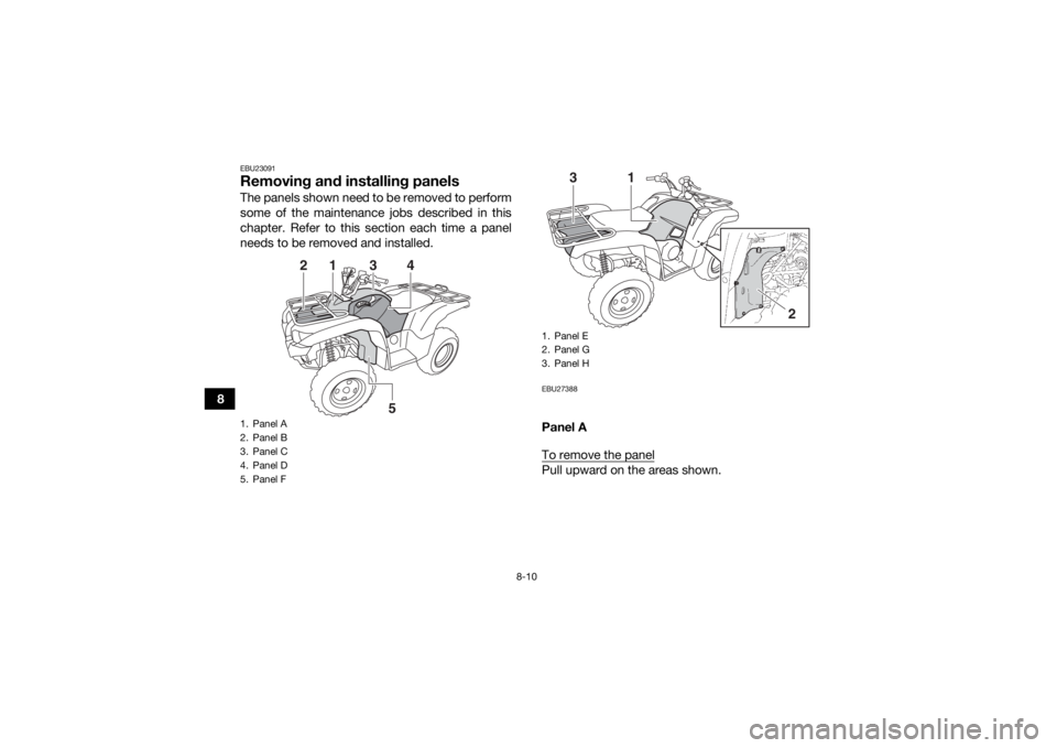
EBU23091Removing and installing panelsThe panels shown need to be removed to perform
some of the maintenance jobs described in this
chapter. Refer to this section each time a panel
needs to be removed and installed.
EBU27388Panel A
To remove the panelPull upward on the areas shown.
1. Panel A
2. Panel B
3. Panel C
4. Panel D
5. Panel F
1
2
3
5
4
1. Panel E
2. Panel G
3. Panel H
1
3
2
U2LB61E0.book Page 10 Friday, February 21, 2014 3:03 PM
Page 103 of 174
8-11
8
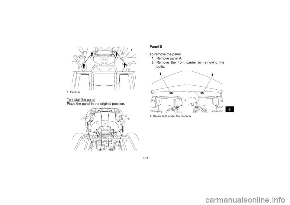
To install the panel
Place the panel in the original position. Panel B
To remove the panel
1. Remove panel A.
2. Remove the front carrier by removing the
bolts.
1. Panel A
1. Carrier bolt (under the fenders)
U2LB61E0.book Page 11 Friday, February 21, 2014 3:03 PM
Page 104 of 174
8-12
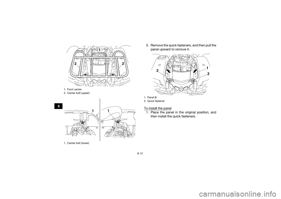
83. Remove the quick fasteners, and then pull the
panel upward to remove it.
To install the panel
1. Place the panel in the original position, and then install the quick fasteners.
1. Front carrier
2. Carrier bolt (upper)
1. Carrier bolt (lower)
1. Panel B
2. Quick fastener
U2LB61E0.book Page 12 Friday, February 21, 2014 3:03 PM
Page 105 of 174
8-13
8
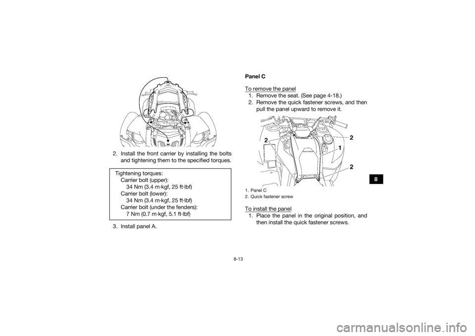
2. Install the front carrier by installing the bolts
and tightening them to the specified torques.
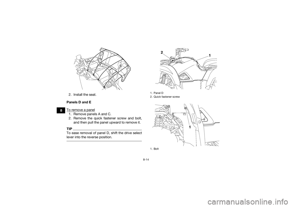
3. Install panel A. Panel C
To remove the panel
1. Remove the seat. (See page 4-18.)
2. Remove the quick fastener screws, and then
pull the panel upward to remove it.
To install the panel1. Place the panel in the original position, and then install the quick fastener screws.
Tightening torques:
Carrier bolt (upper):34 Nm (3.4 m·kgf, 25 ft·lbf)
Carrier bolt (lower): 34 Nm (3.4 m·kgf, 25 ft·lbf)
Carrier bolt (under the fenders): 7 Nm (0.7 m·kgf, 5.1 ft·lbf)1. Panel C
2. Quick fastener screw
U2LB61E0.book Page 13 Friday, February 21, 2014 3:03 PM
Page 106 of 174
8-14
82. Install the seat.
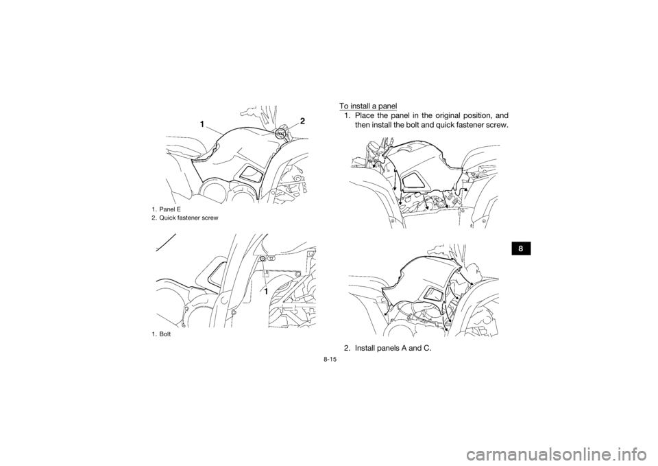
Panels D and E
To remove a panel
1. Remove panels A and C.
2. Remove the quick fastener screw and bolt, and then pull the panel upward to remove it.TIPTo ease removal of panel D, shift the drive select
lever into the reverse position.
1. Panel D
2. Quick fastener screw
1. Bolt
U2LB61E0.book Page 14 Friday, February 21, 2014 3:03 PM
Page 107 of 174
8-15
8
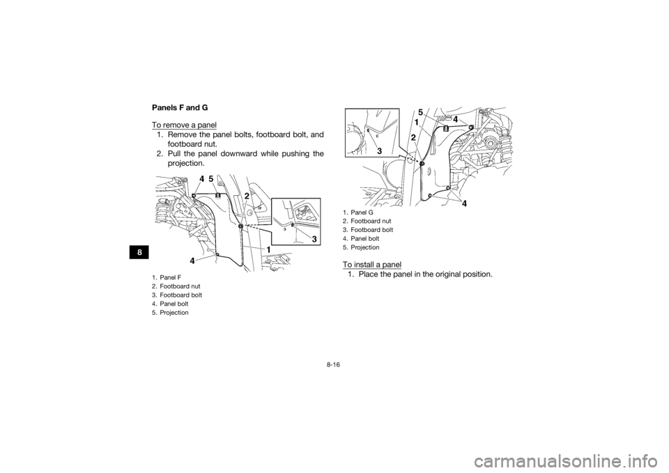
To install a panel
1. Place the panel in the original position, and
then install the bolt and quick fastener screw.
2. Install panels A and C.
1. Panel E
2. Quick fastener screw
1. BoltU2LB61E0.book Page 15 Friday, February 21, 2014 3:03 PM
Page 108 of 174
8-16
8Panels F and G
To remove a panel
1. Remove the panel bolts, footboard bolt, and
footboard nut.
2. Pull the panel downward while pushing the projection.
To install a panel
1. Place the panel in the original position.
1. Panel F
2. Footboard nut
3. Footboard bolt
4. Panel bolt
5. Projection
1. Panel G
2. Footboard nut
3. Footboard bolt
4. Panel bolt
5. Projection
U2LB61E0.book Page 16 Friday, February 21, 2014 3:03 PM
Page 109 of 174
8-17
8
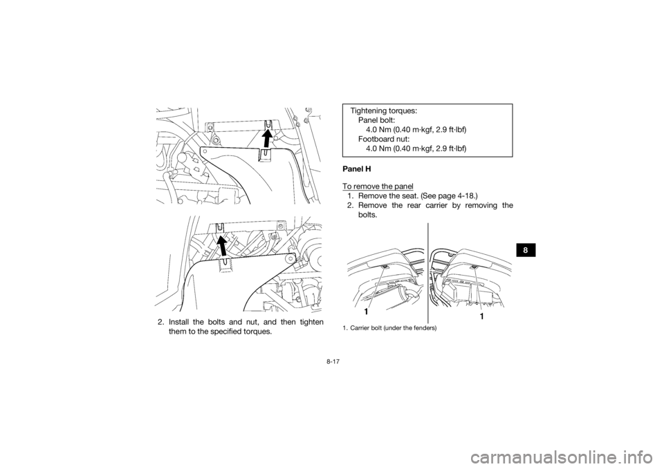
2. Install the bolts and nut, and then tighten them to the specified torques. Panel H
To remove the panel
1. Remove the seat. (See page 4-18.)
2. Remove the rear carrier by removing the
bolts.Tightening torques:Panel bolt:4.0 Nm (0.40 m·kgf, 2.9 ft·lbf)
Footboard nut: 4.0 Nm (0.40 m·kgf, 2.9 ft·lbf)1. Carrier bolt (under the fenders)
U2LB61E0.book Page 17 Friday, February 21, 2014 3:03 PM
Page 110 of 174
8-18
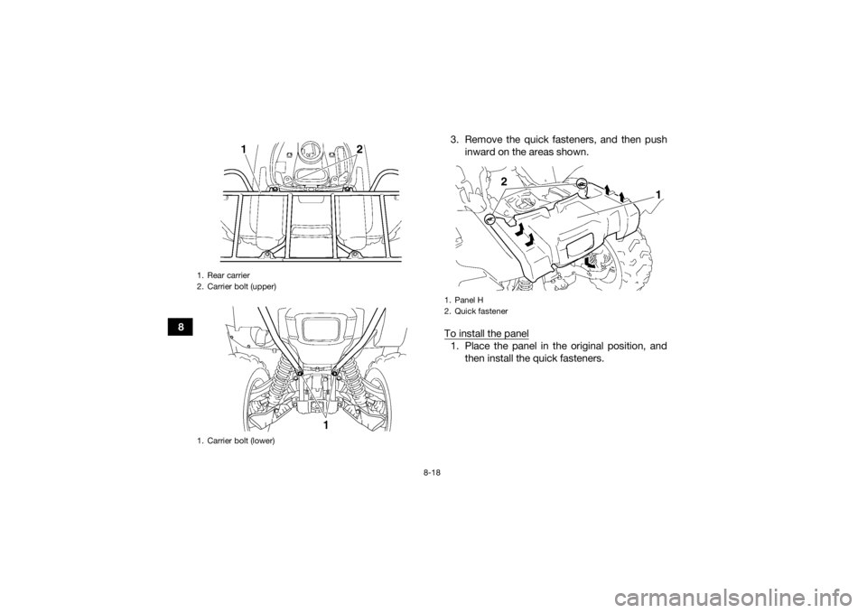
83. Remove the quick fasteners, and then push
inward on the areas shown.
To install the panel
1. Place the panel in the original position, and then install the quick fasteners.
1. Rear carrier
2. Carrier bolt (upper)
1. Carrier bolt (lower)
1. Panel H
2. Quick fastener
2
1
U2LB61E0.book Page 18 Friday, February 21, 2014 3:03 PM
Trending: brake pads, dimensions, fuel tank capacity, fuel, belt, battery, brake fluid
