YAMAHA KODIAK 700 2019 Owners Manual
Manufacturer: YAMAHA, Model Year: 2019, Model line: KODIAK 700, Model: YAMAHA KODIAK 700 2019Pages: 180, PDF Size: 6.41 MB
Page 131 of 180
8-33
8
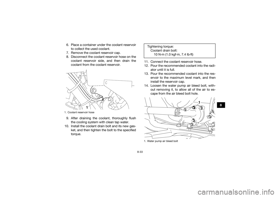
6. Place a container under the coolant reservoir
to collect the used coolant.
7. Remove the coolant reservoir cap.
8. Disconnect the coolant reservoir hose on the coolant reservoir side, and then drain the
coolant from the coolant reservoir.
9. After draining the coolant, thoroughly flush the cooling system with clean tap water.
10. Install the coolant drain bolt and its new gas- ket, and then tighten the bolt to the specified
torque. 11. Connect the coolant reservoir hose.
12. Pour the recommended coolant into the radi-
ator until it is full.
13. Pour the recommended coolant into the res- ervoir to the maximum level mark, and then
install the reservoir cap.
14. Loosen the water pump air bleed bolt, with- out removing it, to allow all of the air to es-
cape from the air bleed bolt hole.
1. Coolant reservoir hose
Tightening torque:Coolant drain bolt:10 N·m (1.0 kgf·m, 7.4 lb·ft)1. Water pump air bleed bolt
1
UB5K60E0.book Page 33 Monday, May 28, 2018 11:35 AM
Page 132 of 180
8-34
815. When coolant begins to flow out of the bolt
hole, tighten the water pump air bleed bolt to
the specified torque.
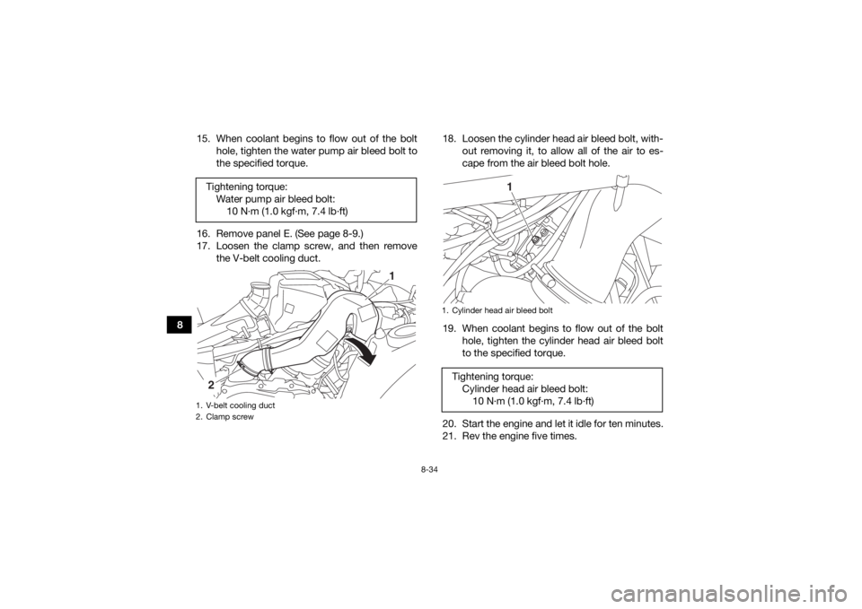
16. Remove panel E. (See page 8-9.)
17. Loosen the clamp screw, and then remove the V-belt cooling duct. 18. Loosen the cylinder head air bleed bolt, with-
out removing it, to allow all of the air to es-
cape from the air bleed bolt hole.
19. When coolant begins to flow out of the bolt hole, tighten the cylinder head air bleed bolt
to the specified torque.
20. Start the engine and let it idle for ten minutes.
21. Rev the engine five times.
Tightening torque:
Water pump air bleed bolt:10 N·m (1.0 kgf·m, 7.4 lb·ft)
1. V-belt cooling duct
2. Clamp screw
1
2
1. Cylinder head air bleed boltTightening torque:Cylinder head air bleed bolt:10 N·m (1.0 kgf·m, 7.4 lb·ft)
1
UB5K60E0.book Page 34 Monday, May 28, 2018 11:35 AM
Page 133 of 180
8-35
8
22. Pour additional coolant into the radiator until
it is full.
23. Stop the engine and allow it to cool. If the coolant level has dropped after the engine
has cooled, add sufficient coolant until it
reaches the top of the radiator, and then in-
stall the radiator cap.
24. Start the engine, and then check for coolant leakage.
TIPIf any leakage is found, have a Yamaha dealer
check the cooling system. 25. Install the V-belt cooling duct, and then tight-en the clamp screw.
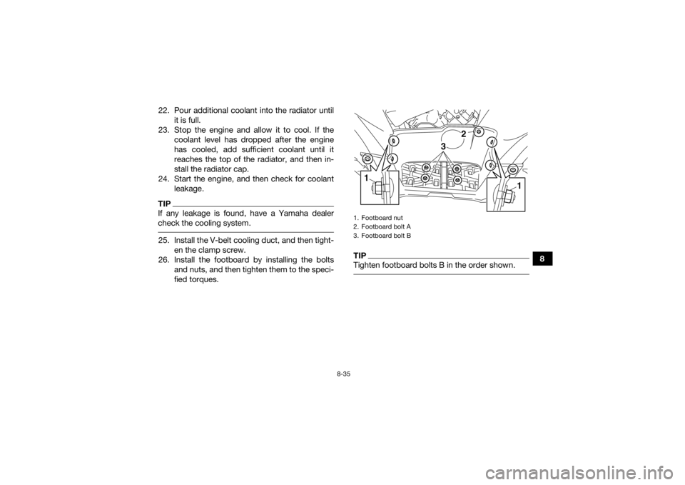
26. Install the footboard by installing the bolts and nuts, and then tighten them to the speci-
fied torques.
TIPTighten footboard bolts B in the order shown. 1. Footboard nut
2. Footboard bolt A
3. Footboard bolt B
3
1
2
1
UB5K60E0.book Page 35 Monday, May 28, 2018 11:35 AM
Page 134 of 180
8-36
827. Install the panels.
EBU34233Cleaning the air filter elementThe air filter element should be cleaned at the in-
tervals specified in the periodic maintenance and
lubrication chart. Clean or replace the air filter ele-
ment more frequently if you ride in unusually wet
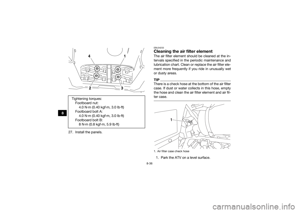
or dusty areas.TIPThere is a check hose at the bottom of the air filter
case. If dust or water collects in this hose, empty
the hose and clean the air filter element and air fil-
ter case. 1. Park the ATV on a level surface.
Tightening torques:
Footboard nut:4.0 N·m (0.40 kgf·m, 3.0 lb·ft)
Footboard bolt A: 4.0 N·m (0.40 kgf·m, 3.0 lb·ft)
Footboard bolt B: 8 N·m (0.8 kgf·m, 5.9 lb·ft)
4
1
2
3
1. Air filter case check hose
1
UB5K60E0.book Page 36 Monday, May 28, 2018 11:35 AM
Page 135 of 180
8-37
8
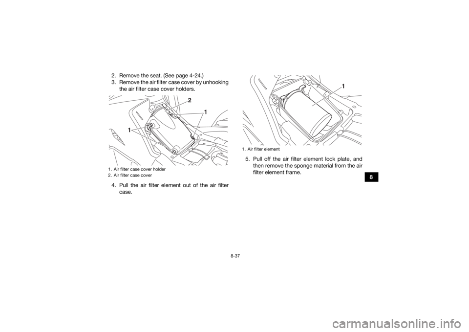
2. Remove the seat. (See page 4-24.)
3. Remove the air filter case cover by unhooking
the air filter case cover holders.
4. Pull the air filter element out of the air filter case. 5. Pull off the air filter element lock plate, and
then remove the sponge material from the air
filter element frame.
1. Air filter case cover holder
2. Air filter case cover
1 2
1
1. Air filter element
1
UB5K60E0.book Page 37 Monday, May 28, 2018 11:35 AM
Page 136 of 180
8-38
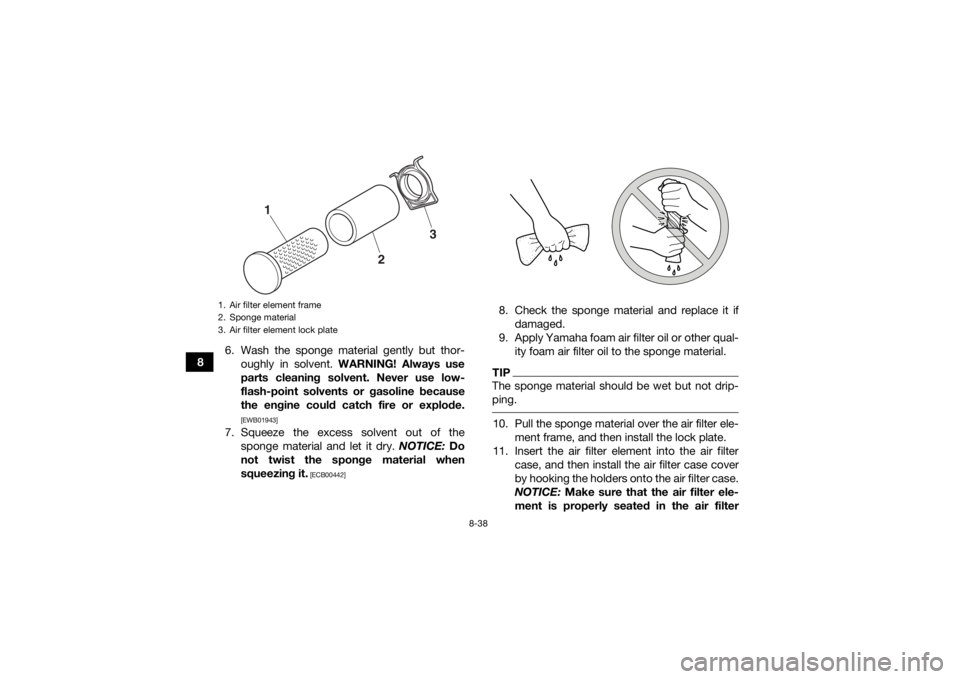
86. Wash the sponge material gently but thor-
oughly in solvent. WARNING! Always use
parts cleaning solvent. Never use low-
flash-point solvents or gasoline because
the engine could catch fire or explode.
[EWB01943]
7. Squeeze the excess solvent out of the sponge material and let it dry. NOTICE: Do
not twist the sponge material when
squeezing it.
[ECB00442]
8. Check the sponge material and replace it if damaged.
9. Apply Yamaha foam air filter oil or other qual- ity foam air filter oil to the sponge material.TIPThe sponge material should be wet but not drip-
ping. 10. Pull the sponge material over the air filter ele- ment frame, and then install the lock plate.
11. Insert the air filter element into the air filter case, and then install the air filter case cover
by hooking the holders onto the air filter case.
NOTICE: Make sure that the air filter ele-
ment is properly seated in the air filter
1. Air filter element frame
2. Sponge material
3. Air filter element lock plate
3
2
1
UB5K60E0.book Page 38 Monday, May 28, 2018 11:35 AM
Page 137 of 180
8-39
8
case. Never operate the engine with the air
filter element removed. Doing so would al-
low unfiltered air to enter the engine, caus-
ing rapid engine wear and possible engine
damage. Additionally, the fuel injection
system would be affected resulting in poor
engine performance and possible over-
heating.
[ECB00763]
12. Install the seat.TIPEach time the air filter element maintenance is
performed, check the air inlet of the air filter case
for obstructions. Check the air filter case rubber
joint to the throttle body and the rubber joint man-
ifold fittings for an air-tight seal. Tighten all fittings
securely to avoid the possibility of unfiltered air
entering the engine. EBU28905Cleaning the spark arresterBe sure the exhaust pipe and muffler are cool be-
fore cleaning the spark arrester.
WARNING
EWB02342Always let the exhaust system cool prior to
touching exhaust components.
Do not start the engine with the spark arrester
removed. Sparks or exhaust particulate can
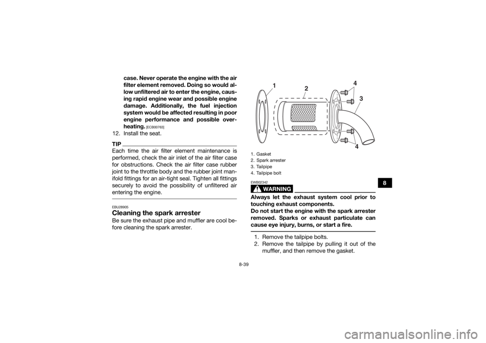
cause eye injury, burns, or start a fire. 1. Remove the tailpipe bolts.
2. Remove the tailpipe by pulling it out of the
muffler, and then remove the gasket.1. Gasket
2. Spark arrester
3. Tailpipe
4. Tailpipe bolt
3
2
4
1
4
UB5K60E0.book Page 39 Monday, May 28, 2018 11:35 AM
Page 138 of 180
8-40
83. Tap the tailpipe lightly, and then use a wire
brush to remove any carbon deposits from
the spark arrester portion of the tailpipe and
inside of the tailpipe housing.
4. Check the gasket for damage. Replace if nec- essary.
5. Install the gasket onto the tailpipe, then insert the tailpipe into the muffler and align the bolt
holes.
6. Install the bolts and tighten to the specified torque.
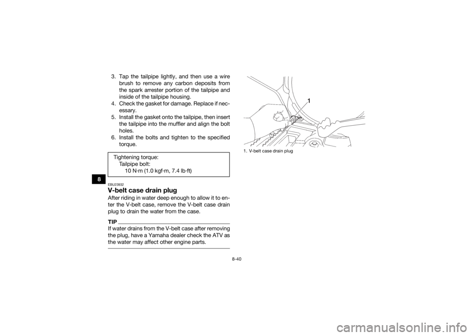
EBU23932V-belt case drain plugAfter riding in water deep enough to allow it to en-
ter the V-belt case, remove the V-belt case drain
plug to drain the water from the case.TIPIf water drains from the V-belt case after removing
the plug, have a Yamaha dealer check the ATV as
the water may affect other engine parts. Tightening torque:Tailpipe bolt:10 N·m (1.0 kgf·m, 7.4 lb·ft)
1. V-belt case drain plug
1
UB5K60E0.book Page 40 Monday, May 28, 2018 11:35 AM
Page 139 of 180
8-41
8
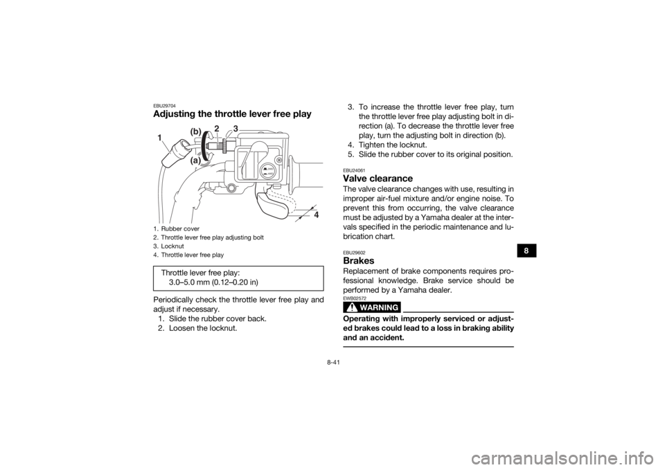
EBU29704Adjusting the throttle lever free playPeriodically check the throttle lever free play and
adjust if necessary.1. Slide the rubber cover back.
2. Loosen the locknut. 3. To increase the throttle lever free play, turn
the throttle lever free play adjusting bolt in di-
rection (a). To decrease the throttle lever free
play, turn the adjusting bolt in direction (b).
4. Tighten the locknut.
5. Slide the rubber cover to its original position.
EBU24061Valve clearanceThe valve clearance changes with use, resulting in
improper air-fuel mixture and/or engine noise. To
prevent this from occurring, the valve clearance
must be adjusted by a Yamaha dealer at the inter-
vals specified in the periodic maintenance and lu-
brication chart.EBU29602BrakesReplacement of brake components requires pro-
fessional knowledge. Brake service should be
performed by a Yamaha dealer.
WARNING
EWB02572Operating with improperly serviced or adjust-
ed brakes could lead to a loss in braking ability
and an accident.
1. Rubber cover
2. Throttle lever free play adjusting bolt
3. Locknut
4. Throttle lever free playThrottle lever free play: 3.0–5.0 mm (0.12–0.20 in)
2WD
4WD
3
2
1
4
(b)
(a)
UB5K60E0.book Page 41 Monday, May 28, 2018 11:35 AM
Page 140 of 180
8-42
8
EBU28414Checking the front brake pads and rear
brake friction platesThe front brake pads and the rear brake friction
plates must be checked for wear at the intervals
specified in the periodic maintenance and lubrica-
tion chart.TIPThis ATV is equipped with a wet, multiple-disc
type rear brake, which is located inside of the final
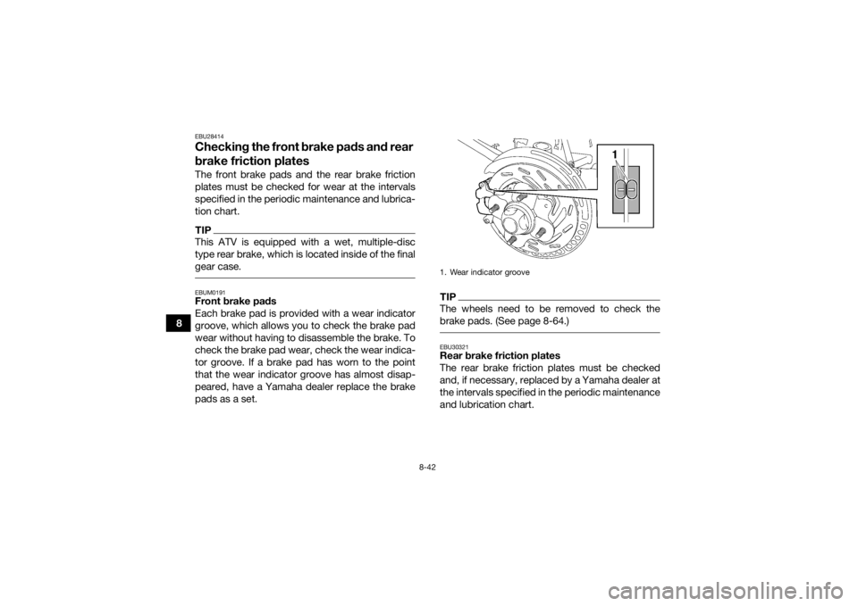
gear case. EBUM0191Front brake pads
Each brake pad is provided with a wear indicator
groove, which allows you to check the brake pad
wear without having to disassemble the brake. To
check the brake pad wear, check the wear indica-
tor groove. If a brake pad has worn to the point
that the wear indicator groove has almost disap-
peared, have a Yamaha dealer replace the brake
pads as a set.
TIPThe wheels need to be removed to check the
brake pads. (See page 8-64.) EBU30321Rear brake friction plates
The rear brake friction plates must be checked
and, if necessary, replaced by a Yamaha dealer at
the intervals specified in the periodic maintenance
and lubrication chart.1. Wear indicator groove
UB5K60E0.book Page 42 Monday, May 28, 2018 11:35 AM