YAMAHA MAJESTY 250 2002 Owner's Guide
Manufacturer: YAMAHA, Model Year: 2002, Model line: MAJESTY 250, Model: YAMAHA MAJESTY 250 2002Pages: 114, PDF Size: 1.96 MB
Page 31 of 114

3-15
INSTRUMENT AND CONTROL FUNCTIONS
3
EAU04284
ECA00104
cCUse only unleaded gasoline. The
use of leaded gasoline will cause
severe damage to internal engine
parts, such as the valves and pis-
ton rings, as well as to the exhaust
system.
EAU03098
Catalytic converterCatalytic converterThis scooter is equipped with a cat-
alytic converter in the muffler.
EW000128
wThe exhaust system is hot after
operation. Make sure that the
exhaust system has cooled down
before doing any maintenance
work.
Your Yamaha engine has been
designed to use regular unleaded
gasoline with a research octane num-
ber of 91 or higher. If knocking (or
pinging) occurs, use a gasoline of a
different brand or premium unleaded
fuel. Use of unleaded fuel will extend
spark plug life and reduce mainte-
nance costs. Recommended fuel:
REGULAR UNLEADED
GASOLINE ONLY
Fuel tank capacity:
Total amount:
12 L
5SJ-28199-E0 1/24/02 6:14 PM Page 30
Page 32 of 114
3-16
INSTRUMENT AND CONTROL FUNCTIONS
3
EC000114
cCThe following precautions must be
observed to prevent a fire hazard
or other damages.
8 8
Use only unleaded gasoline.
The use of leaded gasoline will
cause unrepairable damage to
the catalytic converter.
8 8
Never park the scooter near
possible fire hazards such as
grass or other materials that
easily burn.
8 8
Do not allow the engine to idle
too long.
EAU03091
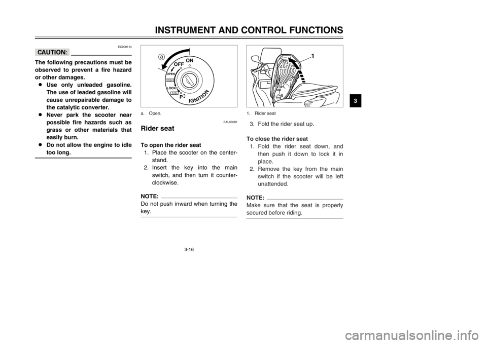
Rider seatRider seatTo open the rider seat
1. Place the scooter on the center-
stand.
2. Insert the key into the main
switch, and then turn it counter-
clockwise.NOTE:
Do not push inward when turning the
key.
IGNITION
P
LOCK
ON
OFF
OPENPUSHPUSH
a
a. Open.
3. Fold the rider seat up.
To close the rider seat
1. Fold the rider seat down, and
then push it down to lock it in
place.
2. Remove the key from the main
switch if the scooter will be left
unattended.NOTE:
Make sure that the seat is properly
secured before riding.
1
1. Rider seat
5SJ-28199-E0 1/24/02 6:14 PM Page 31
Page 33 of 114
3-17
INSTRUMENT AND CONTROL FUNCTIONS
3
EAU03096*
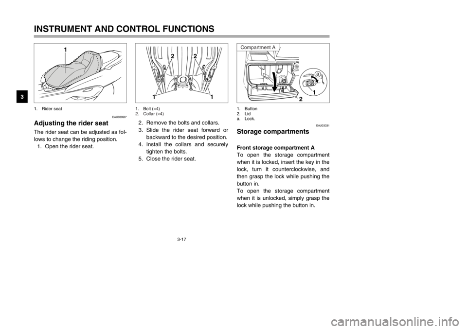
Adjusting the rider seatRider seat, adjustingThe rider seat can be adjusted as fol-
lows to change the riding position.
1. Open the rider seat.
1
1. Rider seat
EAU03331
Storage compartmentsStorage compartmentsFront storage compartment A
To open the storage compartment
when it is locked, insert the key in the
lock, turn it counterclockwise, and
then grasp the lock while pushing the
button in.
To open the storage compartment
when it is unlocked, simply grasp the
lock while pushing the button in.
1
2
a
1. Button
2. Lid
a. Lock.
2. Remove the bolts and collars.
3. Slide the rider seat forward or
backward to the desired position.
4. Install the collars and securely
tighten the bolts.
5. Close the rider seat.
11
2
2
1. Bolt (
×4)
2. Collar (×4)
Compartment A
5SJ-28199-E0 1/24/02 6:14 PM Page 32
Page 34 of 114
3-18
INSTRUMENT AND CONTROL FUNCTIONS
3
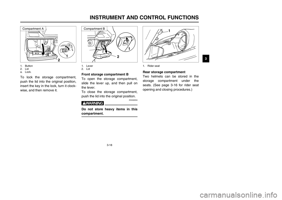
To lock the storage compartment,
push the lid into the original position,
insert the key in the lock, turn it clock-
wise, and then remove it.
1
2
a
1. Button
2. Lid
a. Lock.
Front storage compartment B
To open the storage compartment,
slide the lever up, and then pull on
the lever.
To close the storage compartment,
push the lid into the original position.
EWA00034
wDo not store heavy items in this
compartment.
1
2
1. Lever
2. Lid
Rear storage compartment
Two helmets can be stored in the
storage compartment under the
seats. (See page 3-16 for rider seat
opening and closing procedures.)
1
1. Rider seat
Compartment B
Compartment A
5SJ-28199-E0 1/24/02 6:14 PM Page 33
Page 35 of 114
3-19
INSTRUMENT AND CONTROL FUNCTIONS
3
ECA00051
cCDo not leave the rider seat open
for an extended period of time,
otherwise the light may cause the
battery to discharge.
EWA00035
wDo not exceed the following load-
ing limits:
8 8
Front storage compartment A:
2 kg
8 8
Rear storage compartment:
5 kg
8 8
Maximum load for the vehicle:
185 kg
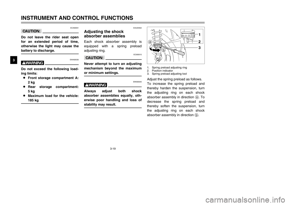
Adjust the spring preload as follows.
To increase the spring preload and
thereby harden the suspension, turn
the adjusting ring on each shock
absorber assembly in direction a. To
decrease the spring preload and
thereby soften the suspension, turn
the adjusting ring on each shock
absorber assembly in direction b.a
b1
23
1. Spring preload adjusting ring
2. Position indicator
3. Spring preload adjusting tool
EAU04552
Adjusting the shock
absorber assembliesShock absorber assemblies, adjustingEach shock absorber assembly is
equipped with a spring preload
adjusting ring.
EC000015
cCNever attempt to turn an adjusting
mechanism beyond the maximum
or minimum settings.
EW000040
wAlways adjust both shock
absorber assemblies equally, oth-
erwise poor handling and loss of
stability may result.
5SJ-28199-E0 1/24/02 6:14 PM Page 34
Page 36 of 114

3-20
INSTRUMENT AND CONTROL FUNCTIONS
3
NOTE:
8Align the appropriate notch in the
adjusting ring with the position
indicator on the shock absorber.
8Use the spring preload adjusting
tool included in the owner’s tool
kit to make this adjustment.
EAU00330
SidestandSidestandThe sidestand is located on the left
side of the frame. Raise the side-
stand or lower it with your foot while
holding the scooter upright.NOTE:
The built-in sidestand switch is part of
the ignition circuit cut-off system,
which cuts the ignition in certain situ-
ations. (See further down for an
explanation of the ignition circuit cut-
off system.)
1
1. Sidestand switch
EW000044
wThe scooter must not be ridden
with the sidestand down, or if the
sidestand cannot be properly
moved up (or does not stay up),
otherwise the sidestand could con-
tact the ground and distract the
operator, resulting in a possible
loss of control. Yamaha’s ignition
circuit cut-off system has been
designed to assist the operator in
fulfilling the responsibility of rais-
ing the sidestand before starting
off. Therefore, check this system
regularly as described below and
have a Yamaha dealer repair it if it
does not function properly.
Setting
Minimum (soft) 1
Standard 4
Maximum (hard) 7
5SJ-28199-E0 1/24/02 6:14 PM Page 35
Page 37 of 114

3-21
INSTRUMENT AND CONTROL FUNCTIONS
3
EAU00337
Ignition circuit cut-off
systemIgnition circuit cut-off systemThe ignition circuit cut-off system
(comprising the sidestand switch and
brake light switches) has the follow-
ing functions.
8It prevents starting when the
sidestand is up, but neither brake
is applied.
8It prevents starting when either
brake is applied, but the side-
stand is still down.
8It cuts the running engine when
the sidestand is moved down.
Periodically check the operation of
the ignition circuit cut-off system
according to the following procedure.
EW000045
wIf a malfunction is noted, have a
Yamaha dealer check the system
before riding.
5SJ-28199-E0 1/24/02 6:14 PM Page 36
Page 38 of 114
3-22
INSTRUMENT AND CONTROL FUNCTIONS
3
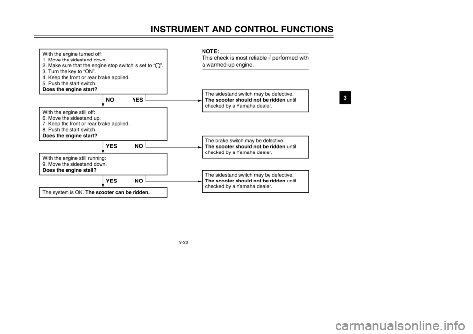
The sidestand switch may be defective.The scooter should not be ridden until
checked by a Yamaha dealer.
YES NO
With the engine turned off:
1. Move the sidestand down.
2. Make sure that the engine stop switch is set to “#”.
3. Turn the key to “ON”.
4. Keep the front or rear brake applied.
5. Push the start switch.
Does the engine start?
The brake switch may be defective.
The scooter should not be ridden until
checked by a Yamaha dealer.
With the engine still off:
6. Move the sidestand up.
7. Keep the front or rear brake applied.
8. Push the start switch.
Does the engine start?With the engine still running:
9. Move the sidestand down.
Does the engine stall?
The sidestand switch may be defective.
The scooter should not be ridden until
checked by a Yamaha dealer.NOTE:This check is most reliable if performed with
a warmed-up engine.
YES NO
The system is OK. The scooter can be ridden.
YES NO
5SJ-28199-E0 1/24/02 6:14 PM Page 37
Page 39 of 114

5SJ-28199-E0 1/24/02 6:14 PM Page 38
Page 40 of 114
PRE-OPERATION CHECKS
Pre-operation check list .....................................................................4-1
4
5SJ-28199-E0 1/24/02 6:14 PM Page 39