seat adjustment YAMAHA MT-03 2020 Owners Manual
[x] Cancel search | Manufacturer: YAMAHA, Model Year: 2020, Model line: MT-03, Model: YAMAHA MT-03 2020Pages: 94, PDF Size: 6.88 MB
Page 5 of 94

Table of contents
Safety information............................1-1
Description........................................2-1
Left view ..........................................2-1
Right view........................................2-2
Controls and instruments ................2-3
Instrument and control functions....3-1
Main switch/steering lock ...............3-1
Indicator lights and warning
lights ............................................3-2
Multi-function meter unit .................3-4
Handlebar switches.......................3-10
Clutch lever ...................................3-11
Shift pedal .....................................3-12
Brake lever ....................................3-12
Brake pedal ...................................3-13
ABS ...............................................3-13
Fuel tank cap.................................3-14
Fuel................................................3-15
Fuel tank overflow hose ................3-16
Catalytic converter ........................3-17
Seats .............................................3-17
Helmet holders ..............................3-19
Storage compartment ...................3-20
Adjusting the shock absorber
assembly....................................3-20
Luggage strap holders ..................3-21
Sidestand ......................................3-22
Ignition circuit cut-off system........3-22
For your safety – pre-operation
checks...............................................4-1
Operation and important riding
points.................................................5-1
Engine break-in ...............................5-1
Starting the engine ..........................5-2
Shifting ............................................5-3
Tips for reducing fuel
consumption ................................5-4
Parking ............................................5-5
Periodic maintenance and
adjustment........................................6-1
Tool kit.............................................6-2Periodic maintenance charts .......... 6-3
Periodic maintenance chart for
the emission control system........ 6-3
General maintenance and
lubrication chart........................... 6-4
Checking the spark plugs ............... 6-7
Canister........................................... 6-8
Engine oil and oil filter cartridge ..... 6-8
Why Yamalube .............................. 6-11
Coolant ......................................... 6-12
Replacing the air filter element
and cleaning the check hose..... 6-13
Checking the throttle grip
free play ..................................... 6-15
Valve clearance ............................. 6-15
Tires .............................................. 6-16
Cast wheels .................................. 6-18
Adjusting the clutch lever
free play ..................................... 6-18
Checking the brake lever
free play ..................................... 6-19
Brake light switches ...................... 6-20
Checking the front and rear
brake pads................................. 6-20
Checking the brake fluid level....... 6-21
Changing the brake fluid............... 6-22
Drive chain slack ........................... 6-23
Cleaning and lubricating the
drive chain ................................. 6-24
Checking and lubricating the
cables ........................................ 6-25
Checking and lubricating the
throttle grip and cable ............... 6-25
Checking and lubricating the
brake and shift pedals ............... 6-26
Checking and lubricating the
brake and clutch levers ............. 6-26
Checking and lubricating the
sidestand ................................... 6-27
Lubricating the swingarm pivots... 6-27
Checking the front fork ................. 6-28
Checking the steering ................... 6-28
Checking the wheel bearings ....... 6-29
Battery .......................................... 6-29
Replacing the fuses ...................... 6-31
Vehicle lights ................................. 6-33
UB6WE0E0.book Page 1 Friday, March 27, 2020 11:37 AM
Page 34 of 94

Instrument and control functions
3-20
3
EAU62550
Storage compartment
The storage compartment is located
under the passenger seat. (See page
3-17.)
When storing documents or other
items in the storage compartment, be
sure to wrap them in a plastic bag so
that they will not get wet. When wash-
ing the vehicle, be careful not to let any
water enter the storage compartment.
WARNING
EWA15401
Do not exceed the maximum load of
160 kg (353 lb) for the vehicle.
EAU68143
Adjusting the shock absorber
assembly
This shock absorber assembly is
equipped with a spring preload adjust-
ing ring.
NOTICE
ECA10102
To avoid damaging the mechanism,
do not attempt to turn beyond the
maximum or minimum settings.
Adjust the spring preload as follows.
TIP
For ABS models, remove the drive
chain guard by removing the bolts and
collars.
Turn the adjusting ring in direction (a)
to increase the spring preload.
Turn the adjusting ring in direction (b)
to decrease the spring preload.
Align the appropriate notch in the
adjusting ring with the position in-
dicator on the shock absorber.
Use the special wrench and the
extension bar included in the tool
kit to make the adjustment.
1. Storage compartment
1
1. Drive chain guard
2. Bolt and collar
2
1
UB6WE0E0.book Page 20 Friday, March 27, 2020 11:37 AM
Page 54 of 94

Periodic maintenance and adjustment
6-10
6
TIP
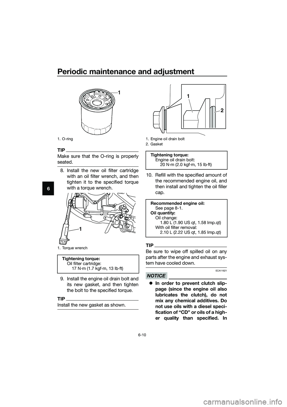
Make sure that the O-ring is properly
seated.
8. Install the new oil filter cartridge
with an oil filter wrench, and then
tighten it to the specified torque
with a torque wrench.
9. Install the engine oil drain bolt and
its new gasket, and then tighten
the bolt to the specified torque.
TIP
Install the new gasket as shown.
10. Refill with the specified amount of
the recommended engine oil, and
then install and tighten the oil filler
cap.
TIP
Be sure to wipe off spilled oil on any
parts after the engine and exhaust sys-
tem have cooled down.
NOTICE
ECA11621
In order to prevent clutch slip-
page (since the engine oil also
lubricates the clutch), do not
mix any chemical additives. Do
not use oils with a diesel speci-
fication of “CD” or oils of a high-
er quality than specified. In
1. O-ring
1. Torque wrench
Tightening torque:
Oil filter cartridge:
17 N·m (1.7 kgf·m, 13 lb·ft)
1
1. Engine oil drain bolt
2. Gasket
Tightening torque:
Engine oil drain bolt:
20 N·m (2.0 kgf·m, 15 lb·ft)
Recommended engine oil:
See page 8-1.
Oil quantity:
Oil change:
1.80 L (1.90 US qt, 1.58 Imp.qt)
With oil filter removal:
2.10 L (2.22 US qt, 1.85 Imp.qt)
2
1
UB6WE0E0.book Page 10 Friday, March 27, 2020 11:37 AM
Page 57 of 94

Periodic maintenance and adjustment
6-13
6 4. Install the reservoir cap, and then
install the coolant reservoir cover
by installing the bolts.EAU33032Changing the coolant
The coolant must be changed at the in-
tervals specified in the periodic mainte-
nance and lubrication chart. Have a
Yamaha dealer change the coolant.
WARNING! Never attempt to remove
the radiator cap when the engine is
hot.
[EWA10382]EAUN1172
Replacing the air filter ele-
ment and cleaning the check
hose
The air filter element should be re-
placed at the intervals specified in the
periodic maintenance and lubrication
chart. Replace the air filter element
more frequently if you are riding in un-
usually wet or dusty areas. In addition,
the air filter check hose must be fre-
quently checked and cleaned if neces-
sary.
To replace the air filter element
1. Remove the rider seat. (See page
3-17.)
2. Remove the left side panel bolts.
3. Remove the left side panel by re-
moving the lower projection on the
panel from the slot, and then re-
moving the upper projection as
shown.
1. Coolant reservoir cap
Coolant reservoir capacity (up to
the maximum level mark):
0.25 L (0.26 US qt, 0.22 Imp.qt)
1
1. Left side panel
2. Bolt
2 1
UB6WE0E0.book Page 13 Friday, March 27, 2020 11:37 AM
Page 58 of 94

Periodic maintenance and adjustment
6-14
64. Lift up the rubber covers, and then
remove the air filter case cover by
removing the screws.
5. Pull the air filter element out.
6. Insert a new air filter element into
the air filter case. NOTICE: Make
sure that the air filter element is
properly seated in the air filtercase. The engine should never
be operated without the air filter
element installed, otherwise the
piston(s) and/or cylinder(s) may
become excessively worn.
[ECA10482]
7. Install the air filter case cover by
installing the screws, and then
place the rubber covers in their
original positions.
8. Place the left side panel in the
original position, and then install
the bolts.
9. Install the rider seat.
To clean the air filter check hose
1. Check the hose on the front of the
air filter case for accumulated dirt
or water.
2. If dirt or water is visible, remove
the hose, clean it, and then install
it.
1. Projection
1. Air filter case cover
2. Screw
3. Rubber cover
1. Air filter element
1
12
23
1
1. Air filter check hose
1
UB6WE0E0.book Page 14 Friday, March 27, 2020 11:37 AM
Page 73 of 94

Periodic maintenance and adjustment
6-29
6
EAU23292
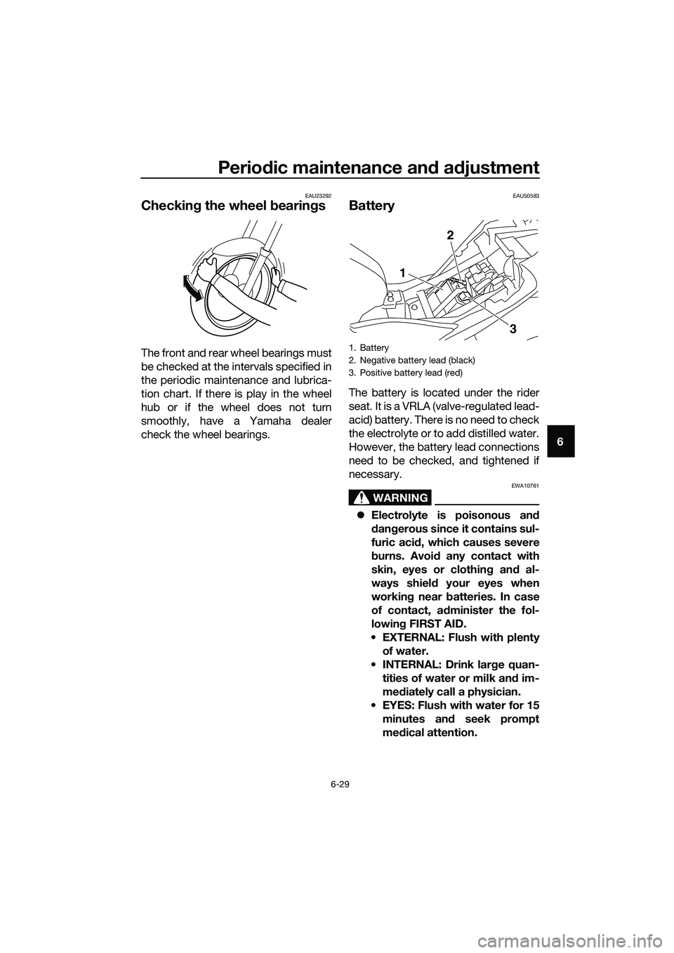
Checking the wheel bearings
The front and rear wheel bearings must
be checked at the intervals specified in
the periodic maintenance and lubrica-
tion chart. If there is play in the wheel
hub or if the wheel does not turn
smoothly, have a Yamaha dealer
check the wheel bearings.
EAU50583
Battery
The battery is located under the rider
seat. It is a VRLA (valve-regulated lead-
acid) battery. There is no need to check
the electrolyte or to add distilled water.
However, the battery lead connections
need to be checked, and tightened if
necessary.
WARNING
EWA10761
Electrolyte is poisonous and
dangerous since it contains sul-
furic acid, which causes severe
burns. Avoid any contact with
skin, eyes or clothing and al-
ways shield your eyes when
working near batteries. In case
of contact, administer the fol-
lowing FIRST AID.
EXTERNAL: Flush with plenty
of water.
INTERNAL: Drink large quan-
tities of water or milk and im-
mediately call a physician.
EYES: Flush with water for 15
minutes and seek prompt
medical attention.
1. Battery
2. Negative battery lead (black)
3. Positive battery lead (red)
1
2
3
UB6WE0E0.book Page 29 Friday, March 27, 2020 11:37 AM
Page 75 of 94

Periodic maintenance and adjustment
6-31
6
EAU62776
Replacing the fuses
The main fuse is located under the
passenger seat. The fuse box, which
contains the fuses for the individual cir-
cuits, is located behind the center pan-
el.
To access the main fuse, proceed as
follows.
1. Remove the passenger seat. (See
page 3-17.)
2. Remove the tray by removing the
quick fasteners.
3. Pull back the starter relay cover.
4. Disconnect the starter relay cou-
pler by pressing from both sides.5. Connect the starter relay coupler,
and then slide the cover to its orig-
inal position.
6. Place the tray in its original posi-
tion, and then install the quick fas-
teners.
7. Install the passenger seat.
TIP
To access the fuse box, remove the
center cover. (See page 3-17.)
1. Quick fastener
2. Tray
1. Starter relay cover
2. Starter relay coupler
3. Main fuse
4. Spare main fuse
2
1
1
2
3
4
1. Fuse box
1. Ignition fuse
2. Signaling system fuse
3. ABS control unit fuse
4. Headlight fuse
5. Backup fuse (for clock)
6. Radiator fan motor fuse
7. Spare fuse
1
71
2
3
5
6
4
UB6WE0E0.book Page 31 Friday, March 27, 2020 11:37 AM