cruise control YAMAHA MT-10 2020 Owners Manual
[x] Cancel search | Manufacturer: YAMAHA, Model Year: 2020, Model line: MT-10, Model: YAMAHA MT-10 2020Pages: 108, PDF Size: 9.22 MB
Page 6 of 108

Table of contentsSafety information........................... 1-1
Description ....................................... 2-1
Left view ......................................... 2-1
Right view ....................................... 2-2
Controls and instruments................ 2-3
Special features ............................... 3-1
Cruise control system ..................... 3-1
D-mode (drive mode)...................... 3-3
Traction control system .................. 3-4
Quick shift system ...... .................... 3-6
Instrument and control
functions ........................................... 4-1
Immobilizer system ..... .................... 4-1
Main switch/steering lock................ 4-2
Handlebar switches ........................ 4-3
Indicator lights and warning lights ............................................ 4-5
Multi-function meter unit ................. 4-8
Clutch lever................................... 4-16
Shift pedal..... ............................ .... 4-16
Brake lever ................................... 4-16
Brake pedal .................................. 4-17
ABS .............................................. 4-17
Fuel tank cap ................................ 4-18
Fuel............................................... 4-19
Fuel tank overflow hose................ 4-21
Catalytic converter ........................ 4-21
Seat .............................................. 4-22 Adjusting the front fork ................. 4-22
Adjusting the shock absorber
assembly................................... 4-24
Luggage strap holders . ................ 4-27
EXUP system ............................... 4-27
Auxiliary DC jack .......................... 4-27
Sidestand ..................................... 4-28
Ignition circuit cut- off system ........ 4-29
For your safety – pre-operation
checks .............................................. 5-1
Operation and important riding
points ................................................ 6-1
Starting the engine ......................... 6-1
Shifting ........................................... 6-2
Tips for reducing fuel consumption ............................... 6-3
Engine break-in .............................. 6-3
Parking ........................................... 6-4
Periodic maintenance and
adjustment ....................................... 7-1
Tool kit............................................ 7-2
Periodic maintenance charts .......... 7-3
Periodic maintenance chart for the emission control system ....... 7-3
General maintenance and
lubrication chart .......................... 7-5
Checking the spark plugs ............... 7-9
Canister ........................................ 7-10 Engine oil ..................................... 7-10
Why Yamalube ............................ 7-14
Coolant ........................................ 7-14
Air filter element ........................... 7-15
Checking the engine idling
speed............ ............................ 7-16
Checking the throttle grip free play ........................................... 7-16
Valve clearance ........................... 7-16
Tires ............................................. 7-17
Cast wheels ................................. 7-19
Adjusting the clutch lever free play ........................................... 7-19
Checking the brake lever free
play ........................................... 7-20
Brake light switches ..................... 7-21
Checking the front and rear
brake pads................................ 7-21
Checking the brake fluid level ...... 7-22
Changing the brake fluid .............. 7-23
Drive chain slack.......................... 7-23
Cleaning and lubricating the drive chain ................................ 7-24
Checking and lubricating the cables ....................................... 7-25
Checking and lubricating the throttle grip and cable ............... 7-25
Checking and lubricating the
brake and shift pedals .............. 7-26
Checking and lubricating the brake and clutch levers ............ 7-26B67-9-E4.book 1 ページ 2019年7月19日 金曜日 午後4時23分
Page 16 of 108
3-1
1
23
4
5
6
7
8
9
10
11
12
Special features
EAU74041
Cruise control systemThis model is equipped with a cruise
control system designed to maintain a
set cruising speed.
The cruise control system operates
only when riding in 4th, 5th or 6th gear
at speeds between about 50 km/h (31
mi/h) and 180 km/h (112 mi/h).
WARNING
EWA16341
Improper use of the cruise con-
trol system may result in loss of
control, which could lead to an
accident. Do not activate the
cruise control system in heavy
traffic, poor weather conditions,
or among winding, slippery,
hilly, rough or gravel roads.
When traveling uphill or down-
hill, the cruise control system
may not be able to maintain the
set cruising speed.
To prevent accidentally activat-
ing the cruise control system,
turn it off when not in use. Make
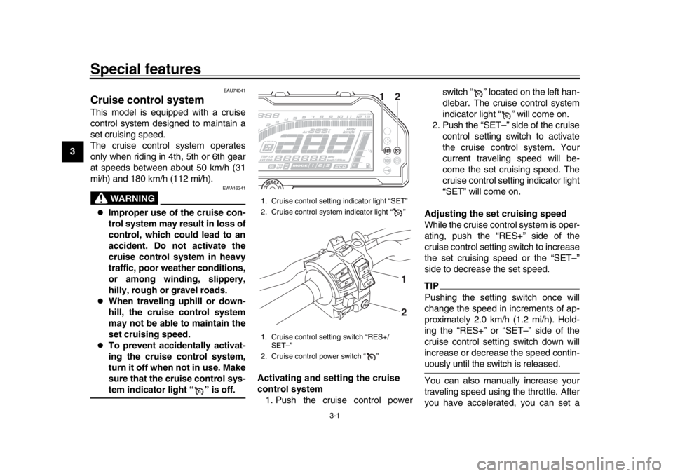
sure that the cruise control sys-tem indicator light “ ” is off. Activating and setting the cruise
control system
1. Push the cruise control power switch “ ” located on the left han-
dlebar. The cruise control system
indicator light “ ” will come on.
2. Push the “SET–” side of the cruise control setting switch to activate
the cruise control system. Your
current traveling speed will be-
come the set cruising speed. The
cruise control setting indicator light
“SET” will come on.
Adjusting the set cruising speed
While the cruise control system is oper-
ating, push the “RES+” side of the
cruise control setting switch to increase
the set cruising speed or the “SET–”
side to decrease the set speed.
TIPPushing the setting switch once will
change the speed in increments of ap-
proximately 2.0 km/h (1.2 mi/h). Hold-
ing the “RES+” or “SET–” side of the
cruise control setting switch down will
increase or decrease the speed contin-uously until the switch is released.
You can also manually increase your
traveling speed using the throttle. After
you have accelerated, you can set a
1. Cruise control setting indicator light “SET”
2. Cruise control system indicator light “ ”
1. Cruise control setting switch “RES+/ SET–”
2. Cruise control power switch “ ”
12
R ESSE T
PAS
S
TC S
SELECT
2 1
B67-9-E4.book 1 ページ 2019年7月19日 金曜日 午後4時23分
Page 17 of 108
Special features
3-2
1
234
5
6
7
8
9
10
11
12
new cruising speed by pushing the
“SET–” side of the setting switch. If you
do not set a new cruising speed, when
you return the throttle grip, the vehicle
will decelerate to the previously set
cruising speed.
Deactivating the cruise control sys-
tem
Perform one of the following operations
to cancel the set cruising speed. The
“SET” indicator light will go off.
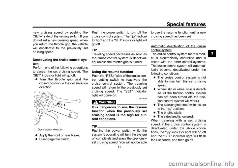
Turn the throttle grip past the
closed position in the deceleration
direction.
Apply the front or rear brake.
Disengage the clutch. Push the power switch to turn off the
cruise control system. The “ ” indica-
tor light and the “SET” indicator light will
go off.
TIPTraveling speed decreases as soon as
the cruise control system is deactivat-ed; unless the throttle grip is turned.
Using the resume function
Push the “RES+” side of the cruise con-
trol setting switch to reactivate the
cruise control system. The traveling
speed will return to the previously set
cruising speed. The “SET” indicator
light will come on.
WARNING
EWA16351
It is dangerous to use the resume
function when the previously set
cruising speed is too high for cur-rent conditions.TIPPushing the power switch while the
system is operating will turn the system
off completely and erase the previously
set cruising speed. You will not be able to use the resume function until a new
cruising speed has been set.
Automatic deactivation of the cruisecontrol systemThe cruise control system for this mod-
el is electronically controlled and is
linked with the other control systems.
The cruise control system will automat-
ically become deactivated under the
following conditions:
The cruise control system is not
able to maintain the set cruising
speed.
Wheel slip or wheel spin is detect-
ed. (If the traction control system
has not been turned off, the trac-
tion control system will work.)
The start/engine stop switch is set
to the “ ” position.
The engine stalls.
The sidestand is lowered.
When traveling with a set cruising
speed, if the cruise control system is
deactivated under the above condi-
tions, the “ ” indicator light will go off
and the “SET” indicator light will flash
for 4 seconds, and then go off.
1. Deceleration direction
1
B67-9-E4.book 2 ページ 2019年7月19日 金曜日 午後4時23分
Page 18 of 108
Special features
3-3
1
23
4
5
6
7
8
9
10
11
12 When not traveling with a set cruising
speed, if the start/engine stop switch is
set to the “ ” position, the engine
stalls, or the sidestand is lowered, then
the “ ” indicator light will go off (the
“SET” indicator light will not flash).
If the cruise control system is automati-
cally deactivated, please stop and con-
firm that your vehicle is in good
operating condition.
Before using the cruise control system
again, activate it using the power
switch.
TIPIn some cases, the cruise control sys-
tem may not be able to maintain the set
cruising speed when the vehicle is trav-
eling uphill or downhill.
When the vehicle is traveling up-
hill, the actual traveling speed may
become lower than the set cruising
speed. If this occurs, accelerate to
the desired traveling speed using
the throttle.
When the vehicle is traveling
downhill, the actual traveling
speed may become higher than
the set cruising speed. If this oc- curs, the setting switch cannot be
used to adjust the set cruising
speed. To reduce the traveling
speed, apply the brakes. When the
brakes are applied, the cruise con-
trol system will become deactivat-
ed.
EAU74053
D-mode (drive mode)D-mode is an electronically-controlled
engine performance system. Select
mode 1 for the most aggressive throttle
response, mode 2 for standard throttle
grip/engine response, and use mode 3
for rainy days or whenever less engine
power is desirable.
WARNING
EWA18440
Do not change the drive mode whilethe vehicle is moving.
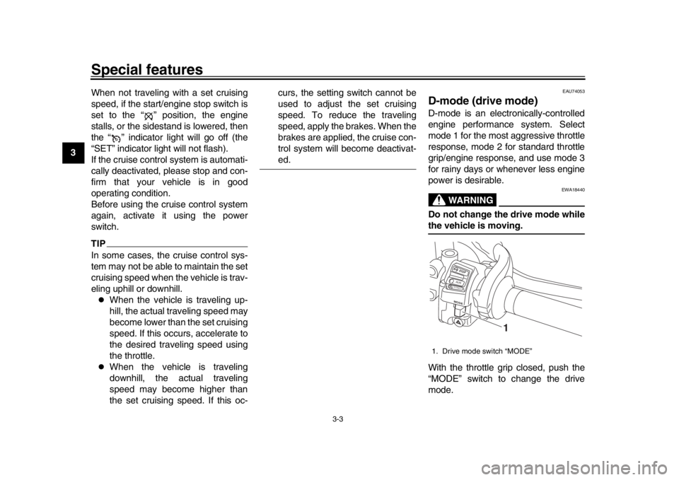
With the throttle grip closed, push the
“MODE” switch to change the drive
mode.1. Drive mode switch “MODE”
STOPM
ODERUNSTA R T
1
B67-9-E4.book 3 ページ 2019年7月19日 金曜日 午後4時23分
Page 24 of 108
Instrument and control functions
4-3
1
2
34
5
6
7
8
9
10
11
12 To unlock the steering
From the “LOCK” position, push the
key in and turn it to “OFF”.
EAU65680
(Parking)
The hazard lights can be turned on, but
all other electrical systems are off. The
key can be removed.
The steering must be locked before the
key can be turned to “ ”.NOTICE
ECA22330
Using the hazard lights for an ex-
tended length of time may cause thebattery to discharge.
EAU66055
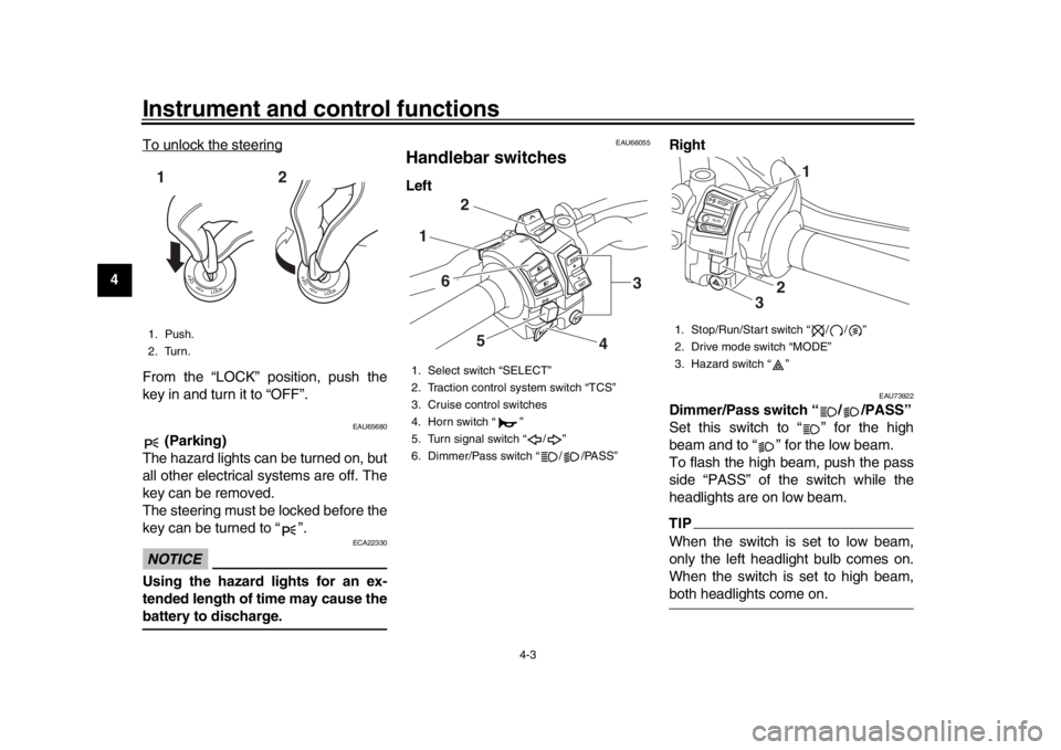
Handlebar switchesLeft Right
EAU73922
Dimmer/Pass switch “ / /PASS”
Set this switch to “ ” for the high
beam and to “ ” for the low beam.
To flash the high beam, push the pass
side “PASS” of the switch while the
headlights are on low beam.TIPWhen the switch is set to low beam,
only the left headlight bulb comes on.
When the switch is set to high beam,both headlights come on.
1. Push.
2. Turn.12
1. Select switch “SELECT”
2. Traction control system switch “TCS”
3. Cruise control switches
4. Horn switch “ ”
5. Turn signal switch “ / ”
6. Dimmer/Pass switch “ / /PASS”
R
ESSE T
PAS
S
TCS
SELECT
1
6
5
4
2
3
1. Stop/Run/Start switch “ / / ”
2. Drive mode switch “MODE”
3. Hazard switch “ ”
STOPMODERUNSTA R T
3
2
1
B67-9-E4.book 3 ページ 2019年7月19日 金曜日 午後4時23分
Page 25 of 108
Instrument and control functions
4-4
1
2
345
6
7
8
9
10
11
12
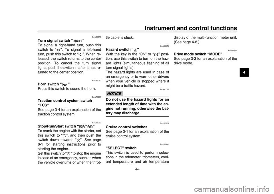
EAU66040
Turn signal switch “ / ”
To signal a right-hand turn, push this
switch to “ ”. To signal a left-hand
turn, push this switch to “ ”. When re-
leased, the switch returns to the center
position. To cancel the turn signal
lights, push the switch in after it has re-
turned to the center position.
EAU66030
Horn switch “ ”
Press this switch to sound the horn.
EAU73961
Traction control system switch
“TCS”
See page 3-4 for an explanation of the
traction control system.
EAU66060
Stop/Run/Start switch “ / / ”
To crank the engine with the starter, set
this switch to “ ”, and then push the
switch down towards “ ”. See page
6-1 for starting instructions prior to
starting the engine.
Set this switch to “ ” to stop the engine
in case of an emergency, such as when
the vehicle overturns or when the throt- tle cable is stuck.
EAU66010
Hazard switch “ ”
With the key in the “ON” or “ ” posi-
tion, use this switch to turn on the haz-
ard lights (simultaneous flashing of all
turn signal lights).
The hazard lights are used in case of
an emergency or to warn other drivers
when your vehicle is stopped where it
might be a traffic hazard.NOTICE
ECA10062
Do not use the hazard lights for an
extended length of time with the en-
gine not running, otherwise the bat-tery may discharge.
EAU73951
Cruise control switches
See page 3-1 for an explanation of the
cruise control system.
EAU73943
“SELECT” switch
This switch is used to perform selec-
tions in the odometer, tripmeters, cool-
ant temperature and air temperature
display of the multi-function meter unit.
(See page 4-8.)
EAU73931
Drive mode switch “MODE”
See page 3-3 for an explanation of the
drive mode.
B67-9-E4.book 4 ページ 2019年7月19日 金曜日 午後4時23分
Page 26 of 108
Instrument and control functions
4-5
1
2
34
5
6
7
8
9
10
11
12
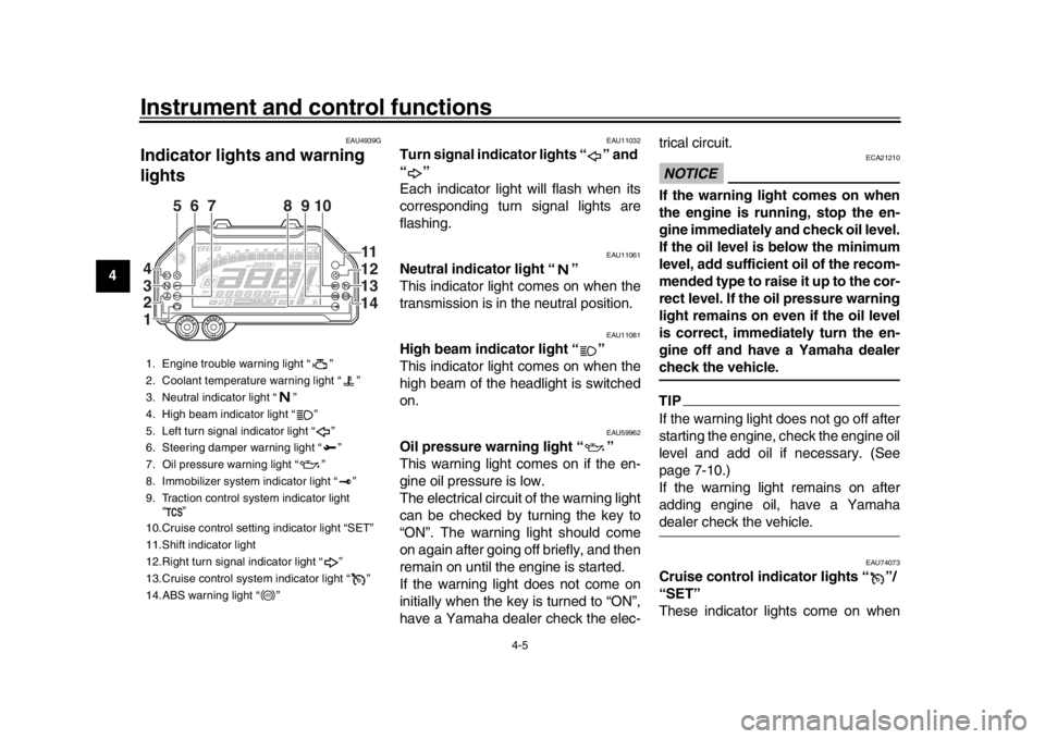
EAU4939G
Indicator ligh ts and warning
lights
EAU11032
Turn signal indicator lights “ ” and
“”
Each indicator light will flash when its
corresponding turn signal lights are
flashing.
EAU11061
Neutral indicator light “ ”
This indicator light comes on when the
transmission is in the neutral position.
EAU11081
High beam indicator light “ ”
This indicator light comes on when the
high beam of the headlight is switched
on.
EAU59962
Oil pressure warning light “ ”
This warning light comes on if the en-
gine oil pressure is low.
The electrical circuit of the warning light
can be checked by turning the key to
“ON”. The warning light should come
on again after going off briefly, and then
remain on until the engine is started.
If the warning light does not come on
initially when the key is turned to “ON”,
have a Yamaha dealer check the elec- trical circuit.
NOTICE
ECA21210
If the warning light comes on when
the engine is running, stop the en-
gine immediately and check oil level.
If the oil level is below the minimum
level, add sufficient oil of the recom-
mended type to raise it up to the cor-
rect level. If the oil pressure warning
light remains on even if the oil level
is correct, immediately turn the en-
gine off and have a Yamaha dealercheck the vehicle.TIPIf the warning light does not go off after
starting the engine, check the engine oil
level and add oil if necessary. (See
page 7-10.)
If the warning light remains on after
adding engine oil, have a Yamahadealer check the vehicle.
EAU74073
Cruise control indicator lights “ ”/
“SET”
These indicator lights come on when
1. Engine trouble warning light “ ”
2. Coolant temperature warning light “ ”
3. Neutral indicator light “ ”
4. High beam indicator light “ ”
5. Left turn signal indicator light “ ”
6. Steering damper warning light “ ”
7. Oil pressure warning light “ ”
8. Immobilizer system indicator light “ ”
9. Traction control system indicator light
“”
10.Cruise control setting indicator light “SET”
11.Shift indicator light
12.Right turn signal indicator light “ ”
13.Cruise control system indicator light “ ”
14.ABS warning light “ ”
567 9 810
11
12
13
14
4
3
2
1
ABS
B67-9-E4.book 5 ページ 2019年7月19日 金曜日 午後4時23分
Page 27 of 108
Instrument and control functions
4-6
1
2
345
6
7
8
9
10
11
12
the cruise control system is activated.
(See page 3-1.)
TIPWhen the vehicle is turned on, these
lights should come on for a few sec-
onds and then go off. Otherwise, havea Yamaha dealer check the vehicle.
EAU11448
Coolant temperature warning light
“”
This warning light comes on when the
engine is overheating.
If this occurs,
stop the engine immediately and allow
the engine to cool.
When the vehicle is turned on, the light
will come on for a few seconds, and
then go off. If the light does not come
on, or if the light remains on, have a
Yamaha dealer check the vehicle. TIP
For vehicles with a radiator fan, the
radiator fan(s) automatically switch
on or off according to the coolant
temperature.
If the engine overheats, see page7-36 for further instructions.
NOTICE
ECA10022
Do not continue to operate the en-gine if it is overheating.
EAU73172
Engine trouble warning light “ ”
This warning light comes on if a prob-
lem is detected in the engine or other
vehicle control system . If this occurs,
have a Yamaha dealer check the
on-board diagnostic system.TIPWhen the vehicle is turned on, the light
will come on for a few seconds and
then go off. If the light does not come
on, or if the light remains on, have aYamaha dealer check the vehicle.
EAU69892
ABS warning light “ ”
This warning light comes on when the
vehicle is first turned on, and goes off
after starting riding. If the warning light
comes on while riding, the anti-lock
brake system may not work correctly.
(See page 4-17.)
TIPIf the light does not come at all, or if the
light does not go off after traveling 10
km/h (6 mi/h), have a Yamaha dealercheck the vehicle.
WARNING
EWA16041
If the ABS warning light does not go
off after traveling at a speed of 10
km/h (6 mi/h) or higher, or if the
warning light comes on or flashes
while riding, the brake system re-
verts to conventional braking. If ei-
ther of the above occurs, or if the
warning light does not come on at
all, use extra caution to avoid possi-
ble wheel lock during emergency
braking. Have a Yamaha dealer
check the brake system and electri-cal circuits as soon as possible.
EAU74082
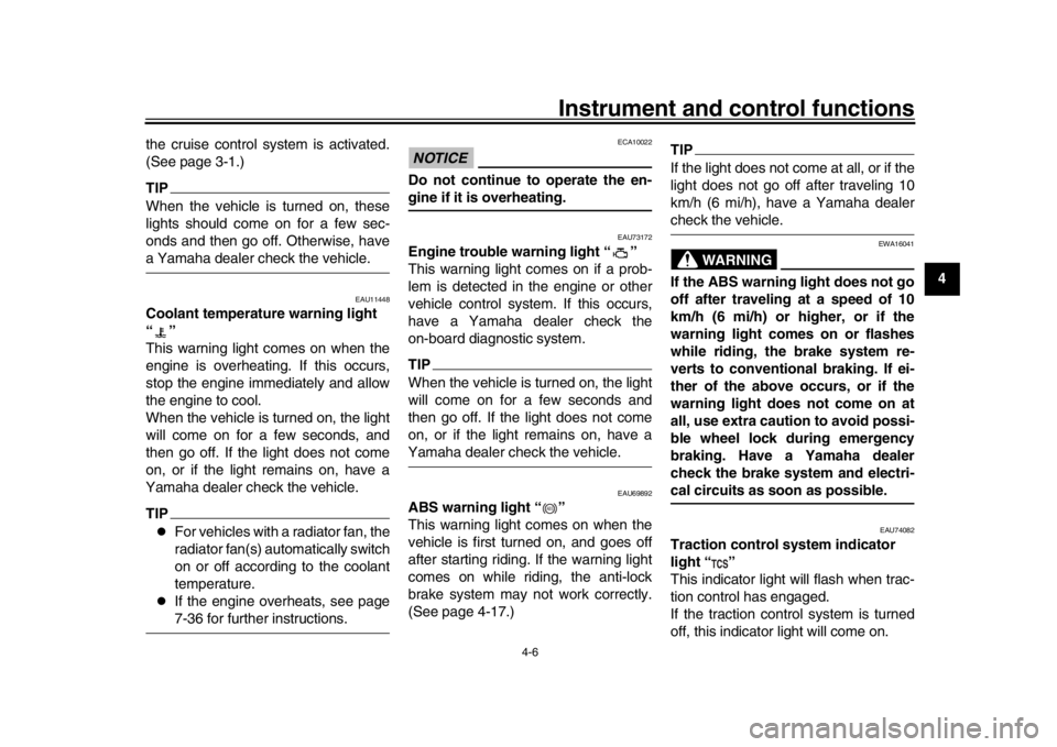
Traction control system indicator
light “ ”
This indicator light will flash when trac-
tion control has engaged.
If the traction control system is turned
off, this indicator light will come on.
ABS
B67-9-E4.book 6 ページ 2019年7月19日 金曜日 午後4時23分
Page 55 of 108
6-1
1
2
3
4
567
8
9
10
11
12
Operation and important riding points
EAU15952
Read the Owner’s Manual carefully to
become familiar with all controls. If
there is a control or function you do not
understand, ask your Yamaha dealer.
WARNING
EWA10272
Failure to familiarize yourself with
the controls can lead to loss of con-
trol, which could cause an accidentor injury.
EAUM3632
TIPThis model is equipped with:
a lean angle sensor. This sensor
stops the engine in case of a vehi-
cle turnover. If this happens, the
engine trouble warning light will
come on, but this is not a malfunc-
tion. Turn the vehicle power off
and then back on again to cancel
the warning light. Failing to do so
will prevent the engine from start-
ing even though the engine will
crank when pushing the start
switch.
an engine auto-stop system. The
engine stops automatically if left
idling for 20 minutes. If the engine
stops, simply push the start switchto restart the engine.
EAU74012
Starting the engineIn order for the ignition circuit cut-off
system to enable starting, one of the
following conditions must be met:
The transmission is in the neutral
position.
The transmission is in gear with
the clutch lever pulled and the sid-
estand up.
See page 4-29 for more informa-
tion.
1. Turn the key to “ON” and make sure that the stop/run/start switch
is set to “ ”.
The following warning lights and
indicator lights should come on for
a few seconds, then go off.
Oil pressure warning light
Engine trouble warning light
Coolant temperature warning
light
Shift indicator light
Steering damper warning light
Traction control system indica-
tor light
Cruise control indicator lights
Immobilizer system indicator
light
B67-9-E4.book 1 ページ 2019年7月19日 金曜日 午後4時23分
Page 89 of 108
Periodic maintenance and adjustment7-31
1
2
3
4
5
678
9
10
11
12
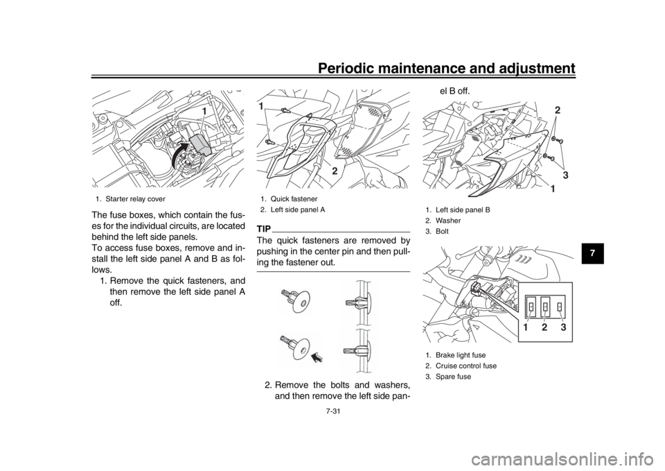
The fuse boxes, which contain the fus-
es for the individual circuits, are located
behind the left side panels.
To access fuse boxes, remove and in-
stall the left side panel A and B as fol-
lows.
1. Remove the quick fasteners, and then remove the left side panel A
off.
TIPThe quick fasteners are removed by
pushing in the center pin and then pull-ing the fastener out.
2. Remove the bolts and washers, and then remove the left side pan- el B off.
1. Starter relay cover
1
1. Quick fastener
2. Left side panel A1
2
1. Left side panel B
2. Washer
3. Bolt
1. Brake light fuse
2. Cruise control fuse
3. Spare fuse
13232
1
B67-9-E4.book 31 ページ 2019年7月19日 金曜日 午後4時23分