engine YAMAHA NIKEN GT 2020 User Guide
[x] Cancel search | Manufacturer: YAMAHA, Model Year: 2020, Model line: NIKEN GT, Model: YAMAHA NIKEN GT 2020Pages: 108, PDF Size: 9.92 MB
Page 22 of 108
Instrument and control functions
3-7
3
EAU86011
Traction control system in dicator
li g ht “TCS”
This indicator light will flash for a few
seconds when traction control has en-
gaged. The indicator light will come on
when the traction control system is
turned off. (See page 3-22.)TIPWhen the vehicle is turned on, this light
should come on for a few seconds and
then go off. Otherwise, have a Yamaha
dealer check vehicle.
EAU74091
Shift in dicator li ght
This indicator light can be set to come
on and go off at select engine speeds.
(See page 3-17.)TIPWhen the vehicle is turned on, the light
should come on for a few seconds and
then go off. If the light does not come
on, or if the light remains on, have a
Yamaha dealer check the vehicle.
EAU73121
Immo bilizer system in dicator
li g ht “ ”
When the main switch is turned off and
30 seconds have passed, the indicator
light will flash steadily to indicate the
immobilizer system is enabled. After 24
hours have passed, the indicator light
will stop flashing, however the immobi-
lizer system is still enabled.TIPWhen the vehicle is turned on, this light
should come on for a few seconds and
then go off. If the light does not come
on, or if the light remains on, have a
Yamaha dealer check the vehicle.Transpon der interference
If the immobilizer system indicator light
flashes in the pattern, slowly 5 times
then quickly 2 times, this could be
caused by transponder interference. If
this occurs, try the following. 1. Make sure there are no other im- mobilizer keys close to the main
switch.
2. Use the code re-registering key to start the engine. 3. If the engine starts, turn it off, and
try starting the engine with the
standard keys.
4. If one or both of the standard keys do not start the engine, take the
vehicle and all 3 keys to a Yamaha
dealer to have the standard keys
re-registered.
UB5BE1E0.book Page 7 Wednesday, October 30, 2019 9:59 AM
Page 25 of 108

Instrument and control functions
3-10
3
TIPPushing the power switch while the
system is operating will turn the sys-
tem off completely and erase the previ-
ously set cruising speed. You will not
be able to use the resume function until
a new cruising speed has been set.Automatic deactivation of the cruisecontrol systemThe cruise control system for this mod-
el is electronically controlled and is
linked with the other control systems.
The cruise control system will auto-
matically become deactivated under
the following conditions:
The cruise control system is not
able to maintain the set cruising
speed.
Wheel slip or wheel spin is detect-
ed. (If the traction control system
has not been turned off, the trac-
tion control system will work.)
The start/engine stop switch is set
to the “ ” position.
The engine stalls.
The sidestand is lowered. When traveling with a set cruising
speed, if the cruise control system is
deactivated under the above condi-
tions, the “ ” indicator light will go off
and the “SET” indicator light will flash
for 4 seconds, and then go off.
When not traveling with a set cruising
speed, if the start/engine stop switch is
set to the “ ” position, the engine
stalls, or the sidestand is lowered, then
the “ ” indicator light will go off (the
“SET” indicator light will not flash).
If the cruise control system is automat-
ically deactivated, please stop and
confirm that your vehicle is in good op-
erating condition.
Before using the cruise control system
again, activate it using the power
switch.
TIPIn some cases, the cruise control sys-
tem may not be able to maintain the set
cruising speed when the vehicle is
traveling uphill or downhill.
When the vehicle is traveling up-
hill, the actual traveling speed may
become lower than the set cruis- ing speed. If this occurs, acceler-
ate to the desired traveling speed
using the throttle.
When the vehicle is traveling
downhill, the actual traveling
speed may become higher than
the set cruising speed. If this oc-
curs, the setting switch cannot be
used to adjust the set cruising
speed. To reduce the traveling
speed, apply the brakes. When
the brakes are applied, the cruise
control system will become deac-
tivated.
UB5BE1E0.book Page 10 Wednesday, October 30, 2019 9:59 AM
Page 27 of 108
Instrument and control functions
3-12
3
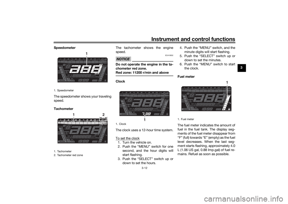
Spee
dometer
The speedometer shows your traveling
speed.
Tachometer The tachometer shows the engine
speed.
NOTICE
ECA10032
Do not operate the en
gine in the ta-
chometer red zone.
Re d zone: 11200 r/min an d a boveClock
The clock uses a 12-hour time system.
To set the clock1. Turn the vehicle on.
2. Push the “MENU” switch for one
second, and the hour digits will
start flashing.
3. Push the “SELECT” switch up or down to set the hours. 4. Push the “MENU” switch, and the
minute digits will start flashing.
5. Push the “SELECT” switch up or down to set the minutes.
6. Push the “MENU” switch to start the clock.
Fuel meter
The fuel meter indicates the amount of
fuel in the fuel tank. The display seg-
ments of the fuel meter disappear from
“F” (full) towards “E” (empty) as the fuel
level decreases. When the last seg-
ment starts flashing, approximately 4.0
L (1.06 US gal, 0.88 Imp.gal) of fuel re-
mains. Refuel as soon as possible.
1. Speedometer
1. Tachometer
2. Tachometer red zone
1
1
2
1. Clock
1
1. Fuel meter
1
UB5BE1E0.book Page 12 Wednesday, October 30, 2019 9:59 AM
Page 28 of 108

Instrument and control functions
3-13
3
TIPIf a problem is detected in the electrical
circuit, the fuel level segments will flash
repeatedly. If this occurs, have a
Yamaha dealer check the vehicle.Eco in dicator
This indicator comes on when the vehi-
cle is being operated in an environ-
mentally friendly, fuel-efficient manner.
The indicator goes off when the vehicle
is stopped.TIPConsider the following tips to reduce
fuel consumption: Avoid high engine speeds during
acceleration.
Travel at a constant speed.
Select the transmission gear that
is appropriate for the vehicle
speed.
Transmission gear display
This display shows the selected gear.
The neutral position is indicated by “N”
and by the neutral indicator light. Drive mo
de display
This display indicates which drive
mode has been selected: “1”, “2” or
“3”. For more details on the modes and
on how to select them, see page 3-18.
TCS display
1. Eco indicator “ECO”
1
1. Neutral indicator light “ ”
2. Transmission gear display
1
2
1. Drive mode display
1. TCS display
1
1
UB5BE1E0.book Page 13 Wednesday, October 30, 2019 9:59 AM
Page 29 of 108
Instrument and control functions
3-14
3
This display indicates which traction
control system setting has been se-
lected: “1”, “2”, or “OFF”. For more de-
tails on the TCS settings and how to
select them, see page 3-22.
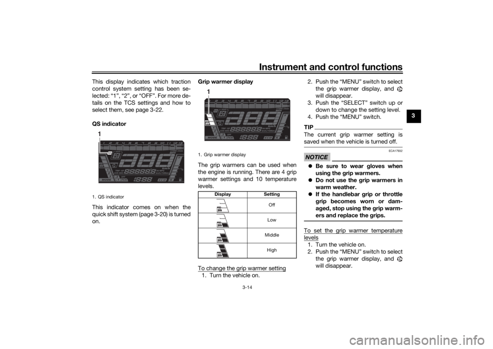
QS in
dicator
This indicator comes on when the
quick shift system (page 3-20) is turned
on. Grip warmer d
isplay
The grip warmers can be used when
the engine is running. There are 4 grip
warmer settings and 10 temperature
levels.
To change the grip warmer setting
1. Turn the vehicle on. 2. Push the “MENU” switch to select
the grip warmer display, and
will disappear.
3. Push the “SELECT” switch up or down to change the setting level.
4. Push the “MENU” switch.
TIPThe current grip warmer setting is
saved when the vehicle is turned off.NOTICE
ECA17932
Be sure to wear g loves when
usin g the g rip warmers.
Do not use the grip warmers in
warm weather.
If the han dle bar grip or throttle
g rip becomes worn or d am-
a g ed , stop usin g the grip warm-
ers an d replace the grips.To set the grip warmer temperaturelevels1. Turn the vehicle on.
2. Push the “MENU” switch to select
the grip warmer display, and
will disappear.
1. QS indicator1
1. Grip warmer display
Display Settin g
Off
Low
Middle High
1
UB5BE1E0.book Page 14 Wednesday, October 30, 2019 9:59 AM
Page 32 of 108
Instrument and control functions
3-17
3 The temperature of the engine coolant
from 40 °C to 124 °C is shown in 1 °C
increments.
If the message “Hi” flashes, stop the
vehicle, then stop the engine and let it
cool. (See page 6-36.)
TIP
When the coolant temperature is
below 40 °C, “Lo” will be dis-
played.
The coolant temperature varies
with changes in the weather and
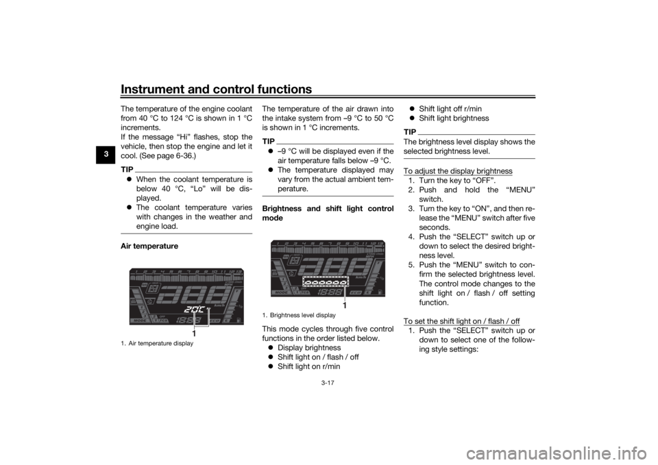
engine load.Air temperature The temperature of the air drawn into
the intake system from –9 °C to 50 °C
is shown in 1 °C increments.
TIP
–9 °C will be displayed even if the
air temperature falls below –9 °C.
The temperature displayed may
vary from the actual ambient tem-
perature.Brig htness and shift light control
mo de
This mode cycles through five control
functions in the order listed below. Display brightness
Shift light on / flash / off
Shift light on r/min
Shift light off r/min
Shift light brightness
TIPThe brightness level display shows the
selected brightness level.To adjust the display brightness1. Turn the key to “OFF”.
2. Push and hold the “MENU”
switch.
3. Turn the key to “ON”, and then re- lease the “MENU” switch after five
seconds.
4. Push the “SELECT” switch up or down to select the desired bright-
ness level.
5. Push the “MENU” switch to con- firm the selected brightness level.
The control mode changes to the
shift light on / flash / off setting
function.
To set the shift light on / flash / off1. Push the “SELECT” switch up or down to select one of the follow-
ing style settings:
1. Air temperature display
1
1. Brightness level display
1
UB5BE1E0.book Page 17 Wednesday, October 30, 2019 9:59 AM
Page 33 of 108
Instrument and control functions
3-18
3
On setting: the shift light will
come on when the set engine
speed is reached. This setting
is selected when the indicator
light is lit continuously.
Flash setting: the shift light
will flash when the set engine
speed is reached. This setting
is selected when the indicator
light flashes four times per se-
cond.
Off setting: the shift light is
deactivated. This setting is
selected when the indicator
light flashes once every two
seconds.
2. Push the “MENU” switch to con- firm the selection. The control
mode changes to the shift light on
r/min setting function.
To set the shift light on r/min
The shift light can be set between 6000
r/min and 12000 r/min in increments of
200 r/min. 1. Push the “SELECT” switch up or down to select the desired engine
speed for activating the indicator
light. 2. Push the “MENU” switch to con-
firm the selected engine speed.
The control mode changes to the
shift light off r/min setting function.
To set the shift light off r/min
The shift light can be set between 6000
r/min and 12000 r/min in increments of
200 r/min. Be sure to set the off r/min
to a higher engine speed than the on
r/min setting, otherwise the shift light
will not come on. 1. Push the “SELECT” switch up or down to select the desired engine
speed for deactivating the indica-
tor light.
2. Push the “MENU” switch to con- firm the selected engine speed.
The control mode changes to the
shift light brightness setting func-
tion.
To adjust the shift light brightness1. Push the “SELECT” switch up or down to select the desired shift
light brightness level.
2. Push the “MENU” switch to con- firm the selected brightness level
and exit the control mode.
EAU84550
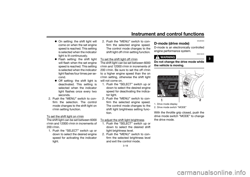
D-mo de ( drive mo de)D-mode is an electronically controlled
engine performance system.
WARNING
EWA18440
Do not chan ge the drive mo de while
the vehicle is movin g.With the throttle grip closed, push the
drive mode switch “MODE” to change
the drive mode.1. Drive mode display
2. Drive mode switch “MODE”
2
1
UB5BE1E0.book Page 18 Wednesday, October 30, 2019 9:59 AM
Page 34 of 108
Instrument and control functions
3-19
3 MODE 3
This mode offers response that is
somewhat less sharp compared to
MODE 2 for riding situations that re-
quire especially sensitive throttle oper-
ation.
MODE 2
This mode is suitable for various riding
conditions.
This mode allows the rider to enjoy
smooth and sporty drivability from the
low-speed range to the high-speed
range.
MODE 1
This mode offers a sportier engine re-
sponse in the low- to mid-speed range
compared to MODE 2.
TIPThe current drive mode is saved when
the vehicle is turned off.
EAU12823
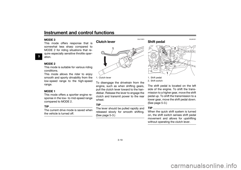
Clutch leverTo disengage the drivetrain from the
engine, such as when shifting gears,
pull the clutch lever toward to the han-
dlebar. Release the lever to engage the
clutch and transmit power to the rear
wheel.TIPThe lever should be pulled rapidly and
released slowly for smooth shifting.
(See page 5-3.)
EAU84321
Shift pe
dalThe shift pedal is located on the left
side of the engine. To shift the trans-
mission to a higher gear, move the shift
pedal up. To shift the transmission to a
lower gear, move the shift pedal down.
(See page 5-3.)TIPWhen the quick shift system is turned
on, the shift switch senses shift pedal
movement and allows for upshifting
without operating the clutch lever.
1. Clutch lever
1
1. Shift pedal
2. Shift switch
2
1
UB5BE1E0.book Page 19 Wednesday, October 30, 2019 9:59 AM
Page 35 of 108
Instrument and control functions
3-20
3
EAU84560
Quick shift systemThe quick shift system (QS) allows for
full-throttle, clutch lever-less, electron-
ically-assisted upshifts. When the shift
switch detects motion in the shift ped-
al, engine power and drive torque are
momentarily adjusted to allow the up-
shift to occur.TIP QS operates when traveling at
least 20 km/h (12 mi/h) with an en-
gine speed of 4000 r/min or high-
er, and only when accelerating.
QS does not operate when the
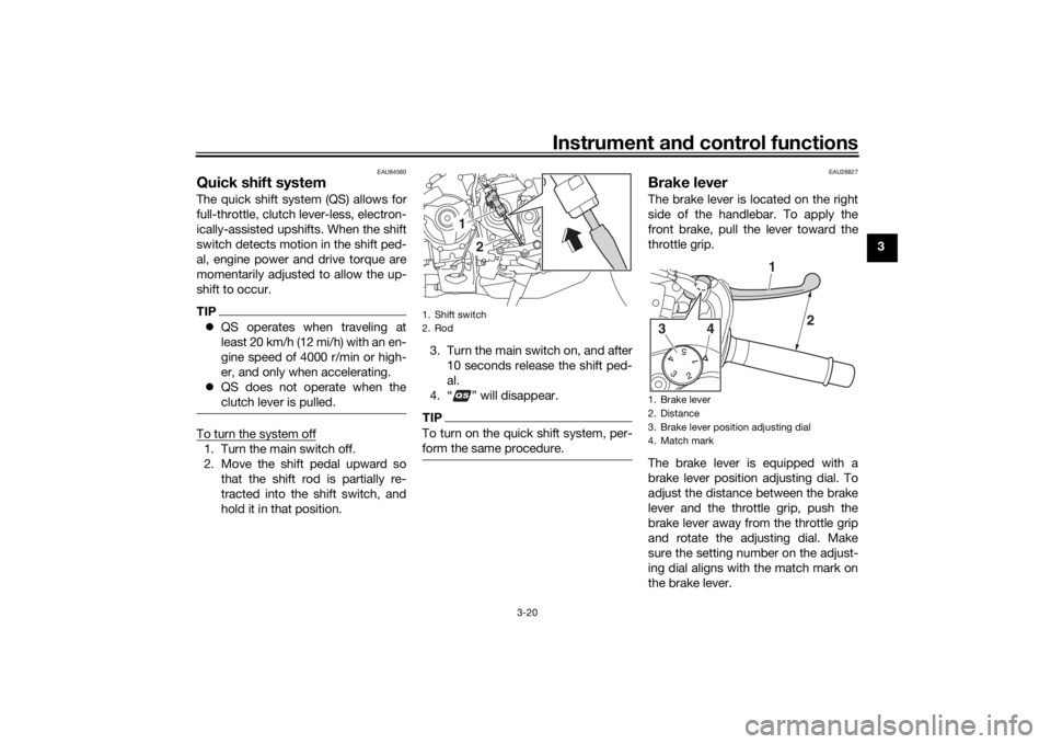
clutch lever is pulled.To turn the system off1. Turn the main switch off.
2. Move the shift pedal upward so
that the shift rod is partially re-
tracted into the shift switch, and
hold it in that position. 3. Turn the main switch on, and after
10 seconds release the shift ped-
al.
4. “ ” will disappear.
TIPTo turn on the quick shift system, per-
form the same procedure.
EAU26827
Brake leverThe brake lever is located on the right
side of the handlebar. To apply the
front brake, pull the lever toward the
throttle grip.
The brake lever is equipped with a
brake lever position adjusting dial. To
adjust the distance between the brake
lever and the throttle grip, push the
brake lever away from the throttle grip
and rotate the adjusting dial. Make
sure the setting number on the adjust-
ing dial aligns with the match mark on
the brake lever.
1. Shift switch
2. Rod
1
2
1. Brake lever
2. Distance
3. Brake lever position adjusting dial
4. Match mark3
4
1
2
UB5BE1E0.book Page 20 Wednesday, October 30, 2019 9:59 AM
Page 37 of 108
Instrument and control functions
3-22
3
EAU76317
Traction control systemThe traction control system (TCS)
helps maintain traction when acceler-
ating on slippery surfaces, such as un-
paved or wet roads. If sensors detect
that the rear wheel is starting to slip
(uncontrolled spinning), the traction
control system assists by regulating
engine power as needed until traction
is restored.
WARNING
EWA15433
The traction control system is not a
su bstitute for ri din g appropriately
for the con ditions. Traction control
cannot prevent loss of traction d ue
to excessive spee d when enterin g
turns, when acceleratin g har d at a
sharp lean an gle, or while brakin g,
an d cannot prevent front wheel slip-
pin g. As with any vehicle, approach
surfaces that may be slippery with
caution an d avoi d especially slip-
pery surfaces.
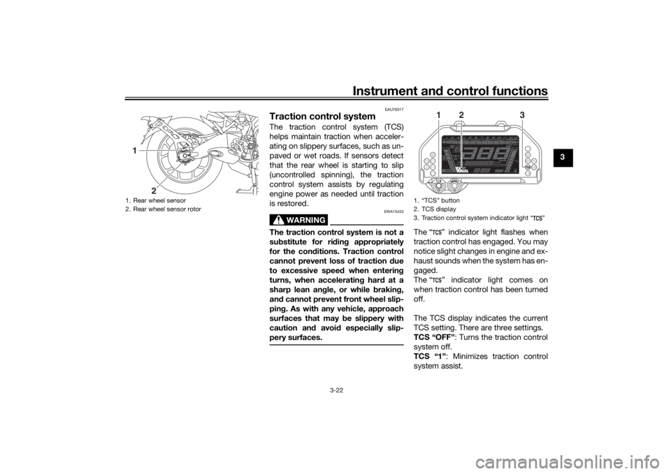
The “ ” indicator light flashes when
traction control has engaged. You may
notice slight changes in engine and ex-
haust sounds when the system has en-
gaged.
The “ ” indicator light comes on
when traction control has been turned
off.
The TCS display indicates the current
TCS setting. There are three settings.
TCS “OFF” : Turns the traction control
system off.
TCS “1” : Minimizes traction control
system assist.
1. Rear wheel sensor
2. Rear wheel sensor rotor1
2
1. “TCS” button
2. TCS display
3. Traction control system indicator light “ ”
1
3
2
UB5BE1E0.book Page 22 Wednesday, October 30, 2019 9:59 AM