engine YAMAHA NMAX 155 2021 User Guide
[x] Cancel search | Manufacturer: YAMAHA, Model Year: 2021, Model line: NMAX 155, Model: YAMAHA NMAX 155 2021Pages: 114, PDF Size: 10.93 MB
Page 39 of 114

Instrument and control functions
6-5
6
EAUN2920
Clock
The clock uses a 12-hour time system.
To set the clock1. Push the “MENU” switch until the
hour digits start flashing.
2. Use the “MENU” switch to set the hours.
3. Push the “MENU” switch until the minute digits start flashing.
4. Use the “MENU” switch to set the minutes.
5. Push the “MENU” switch until the minute digits stop flashing. The
setting is confirmed.
TIPWhen CCU and smartphone is con-
nected after vehicle power on, the
clock is automatically adjusted.
EAU86860
Coolant temperature meter
This meter shows the temperature of
the coolant, and thereby the condition
of the engine. The segments come on
from “C” (cold) to “H” (hot) as the en-
gine temperature increases. If the hot
segment flashes, stop the engine as
soon as possible, and let the engine
cool. (See page 9-37.)
TIPIf a problem is detected in the electrical
circuit, all segments will flash repeat-
edly. Have a Yamaha dealer check the
vehicle.
EAU86870
VVA in dicator
This model is equipped with variable
valve actuation (VVA) for good fuel
economy and acceleration in both the
low-speed and high-speed ranges.
The VVA indicator comes on when the
variable valve actuation system has
switched to the high-speed range.
To turn the VVA indicator on or off1. Turn the vehicle off.
1. Clock
1
1. Coolant temperature meter
1
1. VVA (variable valve actuation) indicator
1
UBBDE0E0.book Page 5 Wednesday, June 2, 2021 2:57 PM
Page 42 of 114
Instrument and control functions
6-8
6
EAUN3060
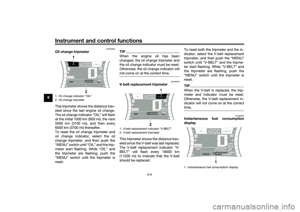
Oil chan ge tripmeter
This tripmeter shows the distance trav-
eled since the last engine oil change.
The oil change indicator “OIL” will flash
at the initial 1000 km (600 mi), the next
5000 km (3100 mi), and then every
6000 km (3700 mi) thereafter.
To reset the oil change tripmeter and
oil change indicator, select the oil
change tripmeter, and then push the
“MENU” switch until “OIL” and the trip-
meter start flashing. While “OIL” and
the tripmeter are flashing, push the
“MENU” switch until the tripmeter is
reset.
TIPWhen the engine oil has been
changed, the oil change tripmeter and
the oil change indicator must be reset.
Otherwise, the oil change indicator will
not come on at the correct time.
EAUN3070
V- belt replacement tripmeter
This tripmeter shows the distance trav-
eled since the V-belt was last replaced.
The V-belt replacement indicator “V-
BELT” will flash every 18000 km
(11200 mi) to indicate that the V-belt
should be replaced. To reset both the tripmeter and the in-
dicator, select the V-belt replacement
tripmeter, and then push the “MENU”
switch until “V-BELT” and the tripme-
ter start flashing. While “V-BELT” and
the tripmeter are flashing, push the
“MENU” switch until the tripmeter is
reset.
TIPWhen the V-belt is replaced, the trip-
meter and indicator must be reset.
Otherwise, the V-belt replacement in-
dicator will not come on at the correct
time.
EAU86940
Instantaneous fuel consumption
d
isplay
1. Oil change indicator “OIL”
2. Oil change tripmeter
2
1
1.
2. V-belt replacement tripmeter
2 1
1. Instantaneous fuel consumption display
1
UBBDE0E0.book Page 8 Wednesday, June 2, 2021 2:57 PM
Page 44 of 114

Instrument and control functions
6-10
6
EAU1234R
Han dle bar switchesLeft Ri
ght
EAU89570
Dimmer switch “ / ”
Set this switch to “ ” for the high
beam and to “ ” for the low beam.TIPWhen the switch is set to low beam,
both upper headlights come on.
When the switch is set to high beam,
both lower headlights also come on.
EAU12461
Turn si gnal switch “ / ”
To signal a right-hand turn, push this
switch to “ ”. To signal a left-hand
turn, push this switch to “ ”. When released, the switch returns to the cen-
ter position. To cancel the turn signal
lights, push the switch in after it has re-
turned to the center position.
EAU12501
Horn switch “ ”
Press this switch to sound the horn.
EAU12722
Start switch “ ”
With the sidestand up, push this switch
while applying the front or rear brake to
crank the engine with the starter. See
page 8-2 for starting instructions prior
to starting the engine.
EAU79500
Hazar
d switch “ ”
With the main switch in the “ON” posi-
tion, use this switch to turn on the haz-
ard lights (simultaneous flashing of all
turn signal lights).
The hazard lights are used in case of an
emergency or to warn other drivers
when your vehicle is stopped where it
might be a traffic hazard.
1. “MENU” switch
2. Dimmer switch “ / ”
3. Turn signal switch “ / ”
4. Horn switch “ ”
1
34
2
1. Stop and Start System switch / Ž
2. Hazard lights switch Ž
3. Start switch Ž
AA
1
2
3
A
A
/
UBBDE0E0.book Page 10 Wednesday, June 2, 2021 2:57 PM
Page 47 of 114
Instrument and control functions
6-13
6
EAUN2810
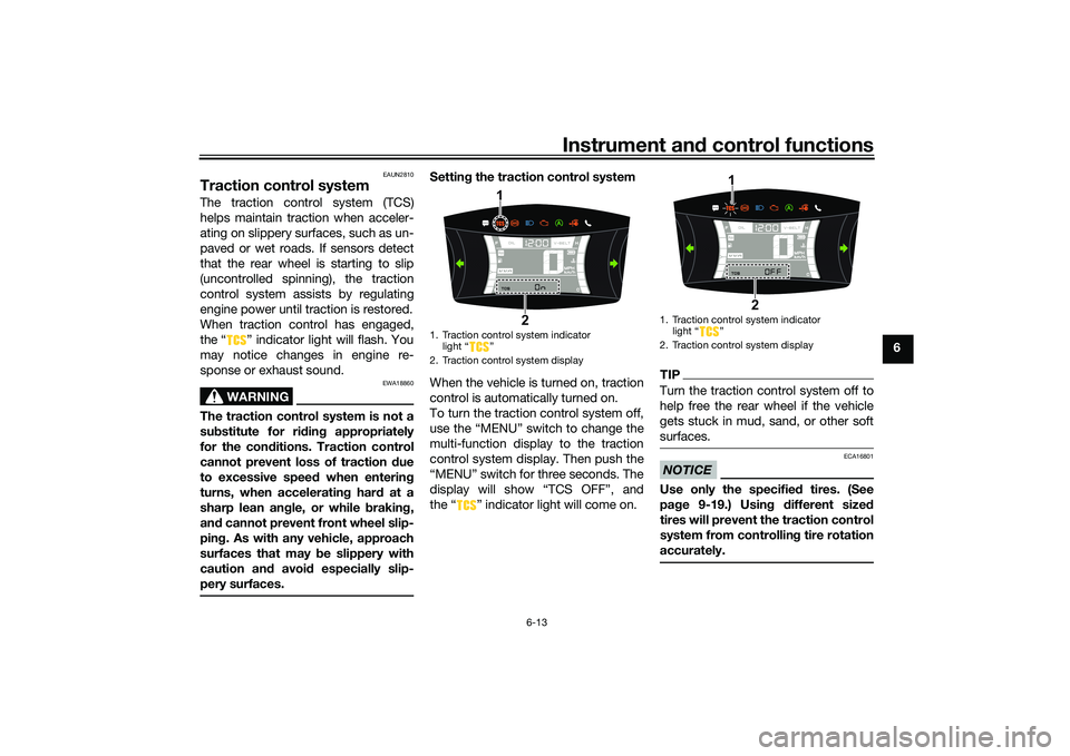
Traction control systemThe traction control system (TCS)
helps maintain traction when acceler-
ating on slippery surfaces, such as un-
paved or wet roads. If sensors detect
that the rear wheel is starting to slip
(uncontrolled spinning), the traction
control system assists by regulating
engine power until traction is restored.
When traction control has engaged,
the “ ” indicator light will flash. You
may notice changes in engine re-
sponse or exhaust sound.
WARNING
EWA18860
The traction control system is not a
su bstitute for ri din g appropriately
for the con ditions. Traction control
cannot prevent loss of traction d ue
to excessive spee d when enterin g
turns, when acceleratin g har d at a
sharp lean an gle, or while b raking,
an d cannot prevent front wheel slip-
pin g. As with any vehicle, approach
surfaces that may be slippery with
caution an d avoi d especially slip-
pery surfaces.
Settin g the traction control system
When the vehicle is turned on, traction
control is automatically turned on.
To turn the traction control system off,
use the “MENU” switch to change the
multi-function display to the traction
control system display. Then push the
“MENU” switch for three seconds. The
display will show “TCS OFF”, and
the “ ” indicator light will come on.
TIPTurn the traction control system off to
help free the rear wheel if the vehicle
gets stuck in mud, sand, or other soft
surfaces.NOTICE
ECA16801
Use only the specifie d tires. (See
pa ge 9-19.) Usin g different size d
tires will prevent the traction control
system from controllin g tire rotation
accurately.
1. Traction control system indicator light “ ”
2. Traction control system display
1
2
1. Traction control system indicator light Ž
2. Traction control system display
1
2
UBBDE0E0.book Page 13 Wednesday, June 2, 2021 2:57 PM
Page 48 of 114
Instrument and control functions
6-14
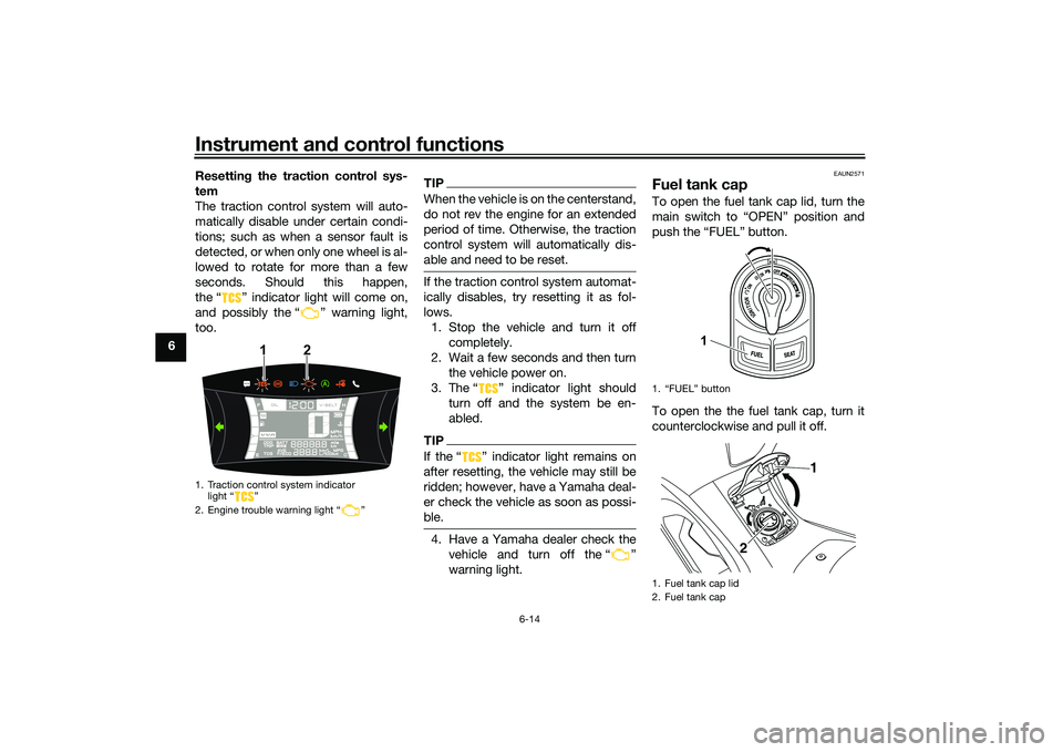
6 Resetting
the traction control sys-
tem
The traction control system will auto-
matically disable under certain condi-
tions; such as when a sensor fault is
detected, or when only one wheel is al-
lowed to rotate for more than a few
seconds. Should this happen,
the “ ” indicator light will come on,
and possibly the “ ” warning light,
too.
TIPWhen the vehicle is on the centerstand,
do not rev the engine for an extended
period of time. Otherwise, the traction
control system will automatically dis-
able and need to be reset.If the traction control system automat-
ically disables, try resetting it as fol-
lows. 1. Stop the vehicle and turn it off completely.
2. Wait a few seconds and then turn the vehicle power on.
3. The Ž indicator light should turn off and the system be en-
abled.TIPIf the Ž indicator light remains on
after resetting, the vehicle may still be
ridden; however, have a Yamaha deal-
er check the vehicle as soon as possi-
ble.4. Have a Yamaha dealer check thevehicle and turn off the Ž
warning light.
EAUN2571
Fuel tank capTo open the fuel tank cap lid, turn the
main switch to “OPEN” position and
push the “FUEL” button.
To open the the fuel tank cap, turn it
counterclockwise and pull it off.
1. Traction control system indicator light “ ”
2. Engine trouble warning light “ ”
1
2
1. “FUEL” button
1. Fuel tank cap lid
2. Fuel tank cap
1
1
2
UBBDE0E0.book Page 14 Wednesday, June 2, 2021 2:57 PM
Page 49 of 114

Instrument and control functions
6-15
6
To install the fuel tank cap, turn it
clockwise until the “ ” mark is facing
forward. Close the fuel tank cap lid.
WARNING
EWA10132
Make sure that the fuel tank cap is
properly installed
before ri din g.
Leakin g fuel is a fire hazar d.
EAU13213
FuelMake sure there is sufficient gasoline in
the tank.
WARNING
EWA10882
Gasoline an d gasoline vapors are
extremely flammab le. To avoid fires
an d explosions an d to re duce the
risk of injury when refueling , follow
these instructions.1. Before refueling, turn off the en- gine and be sure that no one is sit-
ting on the vehicle. Never refuel
while smoking, or while in the vi-
cinity of sparks, open flames, or
other sources of ignition such as
the pilot lights of water heaters
and clothes dryers.
2. Do not overfill the fuel tank. Stop filling when the fuel reaches the
bottom of the filler tube. Because
fuel expands when it heats up,
heat from the engine or the sun
can cause fuel to spill out of the
fuel tank. 3. Wipe up any spilled fuel immedi-
ately. NOTICE: Immediately
wipe off spille d fuel with a clean,
d ry, soft cloth, since fuel may
d eteriorate painte d surfaces or
plastic parts.
[ECA10072]
4. Be sure to securely close the fuel tank cap.
WARNING
EWA15152
Gasoline is poisonous an d can
cause injury or death. Han dle gaso-
line with care. Never siphon gasoline
b y mouth. If you shoul d swallow
some gasoline or inhale a lot of g as-
oline vapor, or get some gasoline in
your eyes, see your doctor imme di-
1. “ ” mark
2. Fuel tank cap
1 2
1. Fuel tank filler tube
2. Maximum fuel level
1
2
UBBDE0E0.book Page 15 Wednesday, June 2, 2021 2:57 PM
Page 50 of 114

Instrument and control functions
6-16
6 ately. If
gasoline spills on your skin,
wash with soap an d water. If gaso-
line spills on your clothin g, chan ge
your clothes.
EAU86072
Your Yamaha engine was designed to
use unleaded gasoline with a research
octane number of 90 or higher. If en-
gine knocking or pinging occurs, use a
gasoline of a different brand or higher
octane rating.
TIP This mark identifies the recom-
mended fuel for this vehicle as
specified by European regulation
(EN228).
Confirm the gasoline pump nozzle
has the same fuel identification
mark.Gasohol
There are two types of gasohol: gaso-
hol containing ethanol and that con-
taining methanol. Gasohol containing
ethanol can be used if the ethanol con-
tent does not exceed 10% (E10). Gas-
ohol containing methanol is not
recommended by Yamaha because it
can cause damage to the fuel system
or vehicle performance problems.
NOTICE
ECA11401
Use only unlea ded g asoline. The use
of lea ded g asoline will cause severe
d amag e to internal en gine parts,
such as the valves an d piston rin gs,
as well as to the exhaust system.
Recommen ded fuel:
Unleaded gasoline (E10 acceptable)
Octane num ber (RON):
90
Fuel tank capacity: 7.1 L (1.9 US gal, 1.6 Imp.gal)
Fuel tank reserve:
1.7 L (0.45 US gal, 0.37 Imp.gal)
E5
E10
UBBDE0E0.book Page 16 Wednesday, June 2, 2021 2:57 PM
Page 55 of 114

Instrument and control functions
6-21
6
EAUN2161
Power outlet This model is equipped with a 12V DC
power outlet.NOTICE
ECAN0140
Do not use the power outlet when
the en gine is off, an d d o not exceed
the specified electrical load ; other-
wise the fuse may blow or the b at-
tery may d ischarge.
When washin g the vehicle, do not di-
rect hi gh-pressure washers at the
power outlet area.
To use the power outlet 1. Turn the vehicle power off.
2. Remove the power outlet cap.
3. Turn the accessory off.
4. Insert the accessory plug into the power outlet.
5. Turn the vehicle power on and start the engine.
6. Turn the accessory on.TIPWhen finished riding, turn off the ac-
cessory and disconnect it from the
power outlet, and then install the cap.
WARNING
EWAN0050
To prevent electrical shock or short-
circuitin g, install the cap when the
power outlet is not in use.
1. Power outletMaximum electrical loa d:
12 W (1A)1
1. Power outlet cap1
UBBDE0E0.book Page 21 Wednesday, June 2, 2021 2:57 PM
Page 57 of 114
Instrument and control functions
6-23
6
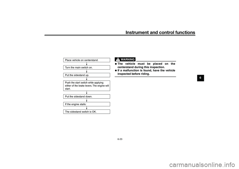
Turn the main switch on.
Put the sidestand up.Push the start switch while applying
either of the brake levers. The engine will
start.Put the sidestand down.
If the engine stalls:
The sidestand switch is OK.Place vehicle on centerstand.
WARNING
The vehicle must be placed on the
centerstand during this inspection.
If a malfunction is found, have the vehicle
inspected before riding.
UBBDE0E0.book Page 23 Wednesday, June 2, 2021 2:57 PM
Page 58 of 114
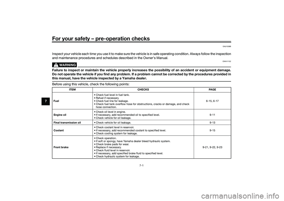
For your safety – pre-operation checks
7-1
7
EAU1559B
Inspect your vehicle each time you use it to make sure the vehicle is in safe operating condition. Always follow the inspection
and maintenance procedures and schedules described in the Owner’s Manual.
WARNING
EWA11152
Failure to inspect or maintain the vehicle properly increases the possibility of an acci dent or equipment d amage.
Do not operate the vehicle if you fin d any pro blem. If a pro blem cannot be corrected b y the proce dures provi ded in
this manual, have the vehicle inspecte d b y a Yamaha dealer.Before using this vehicle, check the following points:
ITEM CHECKS PAGE
Fuel • Check fuel level in fuel tank.
• Refuel if necessary.
• Check fuel line for leakage.
• Check fuel tank overflow hose for obstructions, cracks or damage, and check
hose connection. 6-15, 6-17
En gine oil • Check oil level in engine.
• If necessary, add recommended oil to specified level.
• Check vehicle for oil leakage. 9-11
Final transmission oil • Check vehicle for oil leakage. 9-13
Coolant • Check coolant level in reservoir.
• If necessary, add recommended coolant to specified level.
• Check cooling system for leakage. 9-15
Front brake • Check operation.
• If soft or spongy, have Yamaha dealer bleed hydraulic system.
• Check brake pads for wear.
• Replace if necessary.
• Check fluid level in reservoir.
• If necessary, add specified brake fluid to specified level.
• Check hydraulic system for leakage. 9-21, 9-22, 9-23
UBBDE0E0.book Page 1 Wednesday, June 2, 2021 2:57 PM