check engine YAMAHA NMAX 155 2021 Owners Manual
[x] Cancel search | Manufacturer: YAMAHA, Model Year: 2021, Model line: NMAX 155, Model: YAMAHA NMAX 155 2021Pages: 114, PDF Size: 10.93 MB
Page 8 of 114
Table of contentsSafety information ............................ 1-1
Further safe-riding points ............... 1-5
Description ....................................... 2-1
Left view ......................................... 2-1
Right view ....................................... 2-2
Controls and instruments ............... 2-3
Smart key system ........................... 3-1
Smart key system ........................... 3-1
Operating range of the smart key system .................................. 3-2
Handling of the smart key and mechanical keys ......................... 3-3
Smart key ....................................... 3-4
Replacing the smart key battery..... 3-6
Main switch .................................... 3-7
Stop an d Start System ..................... 4-1
Stop and Start System ................... 4-1
Stop and Start System operation ... 4-1
Special features .............................. 5-1
CCU (Communication Control Unit) ................................ 5-1
Instrument an d control functions ... 6-1
Indicator lights and warning lights............................................ 6-1
Multi-function meter unit ................ 6-3
Handlebar switches ...................... 6-10 Front brake lever ........................... 6-11
Rear brake lever ............................ 6-11
ABS ............................................... 6-12
Traction control system ................ 6-13
Fuel tank cap ................................ 6-14
Fuel ............................................... 6-15
Fuel tank overflow hose ................ 6-17
Catalytic converter ........................ 6-17
Seat ............................................... 6-17
Helmet holders .............................. 6-18
Storage compartments ................. 6-19
Adjusting the shock absorber
assemblies ................................. 6-20
Power outlet ................................. 6-21
Sidestand ...................................... 6-22
Ignition circuit cut-off system ....... 6-22
For your safety – pre-operation
checks ............................................... 7-1
Operation an d important ri din g
points ................................................. 8-1
Engine break-in ............................... 8-1
Starting the engine .......................... 8-2
Starting off ...................................... 8-2
Acceleration and deceleration ........ 8-3
Braking ............................................ 8-3
Tips for reducing fuel consumption ................................ 8-3
Parking ........................................... 8-4 Perio
dic maintenance an d
a d justment ........................................ 9-1
Tool kit ............................................ 9-1
Periodic maintenance chart for the emission control system ....... 9-2
General maintenance and lubrication chart .......................... 9-3
Removing and installing panels ...... 9-7
Checking the spark plug................. 9-9
Canister ........................................ 9-11
Engine oil and oil strainer ............. 9-11
Why Yamalube.............................. 9-13
Final transmission oil .................... 9-13
Coolant ......................................... 9-15
Air filter and V-belt case
air filter elements ....................... 9-16
Checking the throttle grip
free play..................................... 9-19
Valve clearance............................. 9-19
Tires .............................................. 9-19
Cast wheels .................................. 9-21
Checking the front and rear brake lever free play .................. 9-21
Checking the front and rear brake pads ................................ 9-22
Checking the brake fluid level ...... 9-23
Changing the brake fluid .............. 9-24
Checking the V-belt ...................... 9-24
Checking and lubricating the
cables ........................................ 9-25UBBDE0E0.book Page 1 Wednesday, June 2, 2021 2:57 PM
Page 12 of 114
Safety information
1-3
1Avoi
d Car bon Monoxi de Poisonin g
All engine exhaust contains carbon
monoxide, a deadly gas. Breathing
carbon monoxide can cause head-
aches, dizziness, drowsiness, nausea,
confusion, and eventually death.
Carbon Monoxide is a colorless, odor-
less, tasteless gas which may be
present even if you do not see or smell
any engine exhaust. Deadly levels of
carbon monoxide can collect rapidly
and you can quickly be overcome and
unable to save yourself. Also, deadly
levels of carbon monoxide can linger
for hours or days in enclosed or poorly
ventilated areas. If you experience any
symptoms of carbon monoxide poi-
soning, leave the area immediately, get
fresh air, and SEEK MEDICAL TREAT-
MENT. Do not run engine indoors. Even if
you try to ventilate engine exhaust
with fans or open windows and
doors, carbon monoxide can rap-
idly reach dangerous levels.
Do not run engine in poorly venti-
lated or partially enclosed areas
such as barns, garages, or car-
ports.
Do not run engine outdoors where
engine exhaust can be drawn into
a building through openings such
as windows and doors.
Loa din g
Adding accessories or cargo to your
scooter can adversely affect stability
and handling if the weight distribution
of the scooter is changed. To avoid the
possibility of an accident, use extreme
caution when adding cargo or acces-
sories to your scooter. Use extra care
when riding a scooter that has added
cargo or accessories. Here, along with
the information about accessories be-
low, are some general guidelines to fol-
low if loading cargo to your scooter:
The total weight of the operator, pas-
senger, accessories and cargo must
not exceed the maximum load limit.
Operation of an overloa ded vehicle
coul d cause an acci dent.
When loading within this weight limit,
keep the following in mind:
Cargo and accessory weight
should be kept as low and close to
the scooter as possible. Securely
pack your heaviest items as close
to the center of the vehicle as pos-
sible and make sure to distribute
the weight as evenly as possible
on both sides of the scooter to
minimize imbalance or instability.
Shifting weights can create a sud-
den imbalance. Make sure that
accessories and cargo are se-
curely attached to the scooter be-
fore riding. Check accessory
mounts and cargo restraints fre-
quently.
• Properly adjust the suspension for your load (suspension-ad-
justable models only), and
check the condition and pres-
sure of your tires.
• Never attach any large or heavy items to the handlebar, front
fork, or front fender. Such items
can create unstable handling or
a slow steering response.
This vehicle is not desi gne d to
pull a trailer or to be attached to
a si decar.
Maximum loa d:
167 kg (368 lb)
UBBDE0E0.book Page 3 Wednesday, June 2, 2021 2:57 PM
Page 29 of 114
Stop and Start System
4-1
4
EAU76825
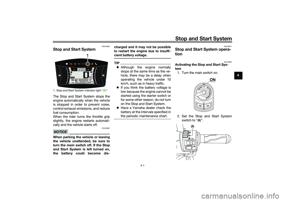
Stop an d Start SystemThe Stop and Start System stops the
engine automatically when the vehicle
is stopped in order to prevent noise,
control exhaust emissions, and reduce
fuel consumption.
When the rider turns the throttle grip
slightly, the engine restarts automati-
cally and the vehicle starts off.NOTICE
ECA23961
When parkin g the vehicle or leavin g
the vehicle unatten ded , be sure to
turn the main switch off. If the Stop
an d Start System is left turne d on,
the battery could become dis- char
ged an d it may not be possi ble
to restart the en gine due to insuffi-
cient battery volta ge.
TIP Although the engine normally
stops at the same time as the ve-
hicle, there may be a delay when
operating the vehicle under 10
km/h, such as in heavy traffic.
If you think the battery voltage is
low because the engine cannot be
started using the starter switch or
for some other reason, do not turn
on the Stop and Start System.
Have a Yamaha dealer check the
battery at the intervals specified in
the periodic maintenance chart.
EAU76671
Stop an d Start System opera-
tion
EAU76687
Activatin g the Stop an d Start Sys-
tem 1. Turn the main switch on.
2. Set the Stop and Start System switch to “ ”.
1. Stop and Start System indicator light “ ”
1
ON
A
AAA
UBBDE0E0.book Page 1 Wednesday, June 2, 2021 2:57 PM
Page 30 of 114

Stop and Start System
4-2
4 3. The Stop and Start System acti-
vates and the indicator light
comes on when the following con-
ditions are met: The Stop and Start System
switch is set to “ ”.
After the engine was warmed
up, the engine was left idling
for a certain period.
The vehicle has traveled at a
speed of 10 km/h or higher.
4. To turn off the Stop and Start Sys- tem, set the Stop and Start Sys-
tem switch to “ ”.
TIPTo preserve battery power, the
Stop and Start System may not
activate.
If the Stop and Start System does
not activate, have a Yamaha deal-
er check the battery.
EAU76832
Stop the en gine
The engine will stop automatically
when the following conditions are met: The Stop and Start System switch
is set to “ ”.
The “ ” indicator light on the
multi-function meter is on.
The vehicle is stopped with the
throttle grip fully returned. At this time, the “ ” indicator light
starts flashing to indicate that the en-
gine is currently stopped by the Stop
and Start System.
EAU76704
Restart the en
gine
If the throttle grip is turned while the
Stop and Start System indicator light is
flashing, the engine will automatically
restart and the “ ” indicator light will
stop flashing.
1. On
A1
A
AAA
A
A
1. On
2. Flashing
A
1
2
A
UBBDE0E0.book Page 2 Wednesday, June 2, 2021 2:57 PM
Page 35 of 114
Instrument and control functions
6-1
6
EAU77123
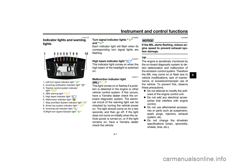
In dicator lig hts and warning
lig hts
EAU88900
Turn si gnal in dicator li ghts “ ”
an d“”
Each indicator light will flash when its
corresponding turn signal lights are
flashing.
EAU88910
Hi gh beam in dicator li ght “ ”
This indicator light comes on when the
high beam of the headlight is switched
on.
EAU88712
Malfunction in dicator li ght
(MIL) “ ”
This light comes on or flashes if a prob-
lem is detected in the engine or other
vehicle control system. If this occurs,
have a Yamaha dealer check the on-
board diagnostic system. The electri-
cal circuit of the warning light can be
checked by turning the vehicle power
on. The light should come on for a few
seconds, and then go off. If the light
does not come on initially when the ve-
hicle power is turned on, or if the light
remains on, have a Yamaha dealer
check the vehicle.
NOTICE
ECA26820
If the MIL starts flashin g, re duce en-
g ine spee d to prevent exhaust sys-
tem damag e.TIPThe engine is sensitively monitored by
the on-board diagnostic system to de-
tect deterioration and malfunction of
the emission control system. Therefore
the MIL may come on or flash due to
vehicle modifications, lack of mainte-
nance, or excessive/improper use of
the vehicle. To prevent this, observe
these precautions.
Do not attempt to modify the soft-
ware of the engine control unit.
Do not add any electrical acces-
sories that interfere with engine
control.
Do not use aftermarket accesso-
ries or parts such as suspension,
spark plugs, injectors, exhaust
system, etc.
Do not change the drivetrain
specifications (chain, sprockets,
wheels, tires, etc.).
1. Left turn signal indicator light “ ”
2. Incoming notification indicator light “ ”
3. Traction control system indicator
light “ ”
4. ABS warning light “ ”
5. High beam indicator light “ ”
6. Malfunction indicator light “ ”
7. Stop and Start System indicator light “ ”
8. Smart key system indicator light “ ”
9. Incoming call indicator light “ ”
10.Right turn signal indicator light “ ”
4
110
5
6
7
8
23 9
UBBDE0E0.book Page 1 Wednesday, June 2, 2021 2:57 PM
Page 36 of 114
Instrument and control functions
6-2
6
Do not remove or alter the O2 sen-
sor, air induction system, or ex-
haust parts (catalysts or EXUP,
etc.).
Maintain V-belt and drive belt (if
equipped) properly.
Maintain correct tire pressure.
Do not operate the vehicle in an
extreme manner. For example, re-
peated or excessive opening and
closing of the throttle, racing,
burnouts, wheelies, etc.
EAU88890
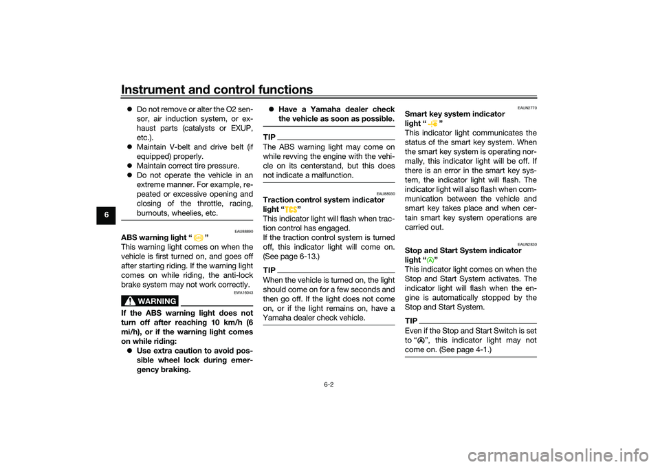
ABS warnin g li ght “ ”
This warning light comes on when the
vehicle is first turned on, and goes off
after starting riding. If the warning light
comes on while riding, the anti-lock
brake system may not work correctly.
WARNING
EWA16043
If the ABS warnin g lig ht does not
turn off after reachin g 10 km/h (6
mi/h), or if the warnin g li ght comes
on while ri din g:
Use extra caution to avoi d pos-
si ble wheel lock d uring emer-
g ency brakin g.
Have a Yamaha dealer check
the vehicle as soon as possib le.
TIPThe ABS warning light may come on
while revving the engine with the vehi-
cle on its centerstand, but this does
not indicate a malfunction.
EAU88930
Traction control system indicator
li g ht “ ”
This indicator light will flash when trac-
tion control has engaged.
If the traction control system is turned
off, this indicator light will come on.
(See page 6-13.)TIPWhen the vehicle is turned on, the light
should come on for a few seconds and
then go off. If the light does not come
on, or if the light remains on, have a
Yamaha dealer check vehicle.
EAUN2770
Smart key system in dicator
li g ht “ ”
This indicator light communicates the
status of the smart key system. When
the smart key system is operating nor-
mally, this indicator light will be off. If
there is an error in the smart key sys-
tem, the indicator light will flash. The
indicator light will also flash when com-
munication between the vehicle and
smart key takes place and when cer-
tain smart key system operations are
carried out.
EAUN2830
Stop an d Start System in dicator
li g ht “ ”
This indicator light comes on when the
Stop and Start System activates. The
indicator light will flash when the en-
gine is automatically stopped by the
Stop and Start System.TIPEven if the Stop and Start Switch is set
to Ž, this indicator light may not
come on. (See page 4-1.)
A
UBBDE0E0.book Page 2 Wednesday, June 2, 2021 2:57 PM
Page 39 of 114

Instrument and control functions
6-5
6
EAUN2920
Clock
The clock uses a 12-hour time system.
To set the clock1. Push the “MENU” switch until the
hour digits start flashing.
2. Use the “MENU” switch to set the hours.
3. Push the “MENU” switch until the minute digits start flashing.
4. Use the “MENU” switch to set the minutes.
5. Push the “MENU” switch until the minute digits stop flashing. The
setting is confirmed.
TIPWhen CCU and smartphone is con-
nected after vehicle power on, the
clock is automatically adjusted.
EAU86860
Coolant temperature meter
This meter shows the temperature of
the coolant, and thereby the condition
of the engine. The segments come on
from “C” (cold) to “H” (hot) as the en-
gine temperature increases. If the hot
segment flashes, stop the engine as
soon as possible, and let the engine
cool. (See page 9-37.)
TIPIf a problem is detected in the electrical
circuit, all segments will flash repeat-
edly. Have a Yamaha dealer check the
vehicle.
EAU86870
VVA in dicator
This model is equipped with variable
valve actuation (VVA) for good fuel
economy and acceleration in both the
low-speed and high-speed ranges.
The VVA indicator comes on when the
variable valve actuation system has
switched to the high-speed range.
To turn the VVA indicator on or off1. Turn the vehicle off.
1. Clock
1
1. Coolant temperature meter
1
1. VVA (variable valve actuation) indicator
1
UBBDE0E0.book Page 5 Wednesday, June 2, 2021 2:57 PM
Page 48 of 114
Instrument and control functions
6-14
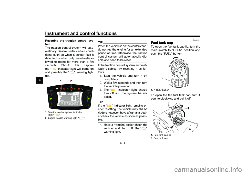
6 Resetting
the traction control sys-
tem
The traction control system will auto-
matically disable under certain condi-
tions; such as when a sensor fault is
detected, or when only one wheel is al-
lowed to rotate for more than a few
seconds. Should this happen,
the “ ” indicator light will come on,
and possibly the “ ” warning light,
too.
TIPWhen the vehicle is on the centerstand,
do not rev the engine for an extended
period of time. Otherwise, the traction
control system will automatically dis-
able and need to be reset.If the traction control system automat-
ically disables, try resetting it as fol-
lows. 1. Stop the vehicle and turn it off completely.
2. Wait a few seconds and then turn the vehicle power on.
3. The Ž indicator light should turn off and the system be en-
abled.TIPIf the Ž indicator light remains on
after resetting, the vehicle may still be
ridden; however, have a Yamaha deal-
er check the vehicle as soon as possi-
ble.4. Have a Yamaha dealer check thevehicle and turn off the Ž
warning light.
EAUN2571
Fuel tank capTo open the fuel tank cap lid, turn the
main switch to “OPEN” position and
push the “FUEL” button.
To open the the fuel tank cap, turn it
counterclockwise and pull it off.
1. Traction control system indicator light “ ”
2. Engine trouble warning light “ ”
1
2
1. “FUEL” button
1. Fuel tank cap lid
2. Fuel tank cap
1
1
2
UBBDE0E0.book Page 14 Wednesday, June 2, 2021 2:57 PM
Page 58 of 114
For your safety – pre-operation checks
7-1
7
EAU1559B
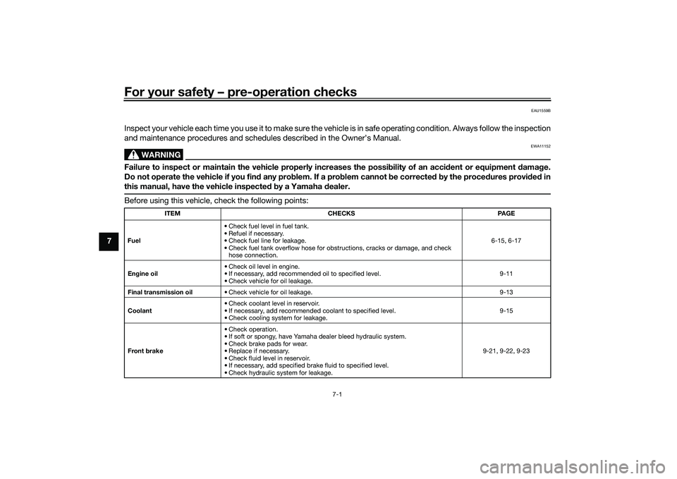
Inspect your vehicle each time you use it to make sure the vehicle is in safe operating condition. Always follow the inspection
and maintenance procedures and schedules described in the Owner’s Manual.
WARNING
EWA11152
Failure to inspect or maintain the vehicle properly increases the possibility of an acci dent or equipment d amage.
Do not operate the vehicle if you fin d any pro blem. If a pro blem cannot be corrected b y the proce dures provi ded in
this manual, have the vehicle inspecte d b y a Yamaha dealer.Before using this vehicle, check the following points:
ITEM CHECKS PAGE
Fuel • Check fuel level in fuel tank.
• Refuel if necessary.
• Check fuel line for leakage.
• Check fuel tank overflow hose for obstructions, cracks or damage, and check
hose connection. 6-15, 6-17
En gine oil • Check oil level in engine.
• If necessary, add recommended oil to specified level.
• Check vehicle for oil leakage. 9-11
Final transmission oil • Check vehicle for oil leakage. 9-13
Coolant • Check coolant level in reservoir.
• If necessary, add recommended coolant to specified level.
• Check cooling system for leakage. 9-15
Front brake • Check operation.
• If soft or spongy, have Yamaha dealer bleed hydraulic system.
• Check brake pads for wear.
• Replace if necessary.
• Check fluid level in reservoir.
• If necessary, add specified brake fluid to specified level.
• Check hydraulic system for leakage. 9-21, 9-22, 9-23
UBBDE0E0.book Page 1 Wednesday, June 2, 2021 2:57 PM
Page 60 of 114

Operation and important rid ing points
8-1
8
EAU15952
Read the Owner’s Manual carefully to
become familiar with all controls. If
there is a control or function you do not
understand, ask your Yamaha dealer.
WARNING
EWA10272
Failure to familiarize yourself with
the controls can lead to loss of con-
trol, which coul d cause an acci dent
or injury.
EAU16842
En gine break-inThere is never a more important period
in the life of your engine than the period
between 0 and 1600 km (1000 mi). For
this reason, you should read the fol-
lowing material carefully.
Since the engine is brand new, do not
put an excessive load on it for the first
1600 km (1000 mi). The various parts in
the engine wear and polish themselves
to the correct operating clearances.
During this period, prolonged full-throt-
tle operation or any condition that
might result in engine overheating
must be avoided.
EAUM2012
0–1000 km (0–600 mi)
Avoid prolonged operation above 1/3
throttle. NOTICE: After 1000 km (600
mi) of operation, be sure to replace
the en gine oil an d final transmission
oil.
[ECA11662]
1000–1600 km (600–1000 mi)
Avoid prolonged operation above 1/2
throttle. 1600 km (1000 mi) an
d b eyon d
The vehicle can now be operated nor-
mally.
NOTICE
ECA10271
If any en gine trou ble shoul d occur
d urin g the en gine break-in perio d,
imme diately have a Yamaha dealer
check the vehicle.
UBBDE0E0.book Page 1 Wednesday, June 2, 2021 2:57 PM