clock YAMAHA NMAX 155 2021 Owners Manual
[x] Cancel search | Manufacturer: YAMAHA, Model Year: 2021, Model line: NMAX 155, Model: YAMAHA NMAX 155 2021Pages: 114, PDF Size: 10.93 MB
Page 37 of 114

Instrument and control functions
6-3
6
EAUN2781
Incomin g call in dicator li ght “ ”
This indicator light flashes when there
is an incoming call to the connected
smartphone. If you do not answer the
call, the indicator light stays on until
you turn the vehicle off.TIPThis function works only when the
smartphone is connected to the vehi-
cle.
EAUN2792
Incomin g notification in dicator
lig ht “ ”
This indicator light flashes for 10 sec-
onds when the connected smartphone
receives an SNS, E-mail or other notifi-
cation. After that, the indicator light
stays on until you turn the vehicle off.TIP This function works only when the
smartphone is connected to the
vehicle.
Notification setting is needed for
each application at the connected
smartphone in advance.
EAUN3040
Multi-function meter unit
WARNING
EWA12423
Be sure to stop the vehicle before
makin g any settin g chan ges to the
multi-function meter unit. Chan gin g
settin gs while ri din g can distract the
operator an d increase the risk of an
acci dent.
The “MENU” switch is located on the
left side of handlebar. This switch al-
lows you to control or change the set-
tings of multi-function meter unit.
The multi-function meter unit is
equipped with the following:
a speedometer
a VVA indicator
a clock
a fuel meter
an App connect icon
a smartphone battery level meter
a coolant temperature meter
a multi-function displayTIPBe sure to turn the main switch on be-
1. Fuel meter
2. App connect icon
3. VVA (variable valve actuation) indicator
4. Clock
5. Speedometer
6. Smartphone battery level meter
7. Coolant temperature meter
8. Multi-function display
8
1345 7
6
2
1.
1
UBBDE0E0.book Page 3 Wednesday, June 2, 2021 2:57 PM
Page 39 of 114

Instrument and control functions
6-5
6
EAUN2920
Clock
The clock uses a 12-hour time system.
To set the clock1. Push the “MENU” switch until the
hour digits start flashing.
2. Use the “MENU” switch to set the hours.
3. Push the “MENU” switch until the minute digits start flashing.
4. Use the “MENU” switch to set the minutes.
5. Push the “MENU” switch until the minute digits stop flashing. The
setting is confirmed.
TIPWhen CCU and smartphone is con-
nected after vehicle power on, the
clock is automatically adjusted.
EAU86860
Coolant temperature meter
This meter shows the temperature of
the coolant, and thereby the condition
of the engine. The segments come on
from “C” (cold) to “H” (hot) as the en-
gine temperature increases. If the hot
segment flashes, stop the engine as
soon as possible, and let the engine
cool. (See page 9-37.)
TIPIf a problem is detected in the electrical
circuit, all segments will flash repeat-
edly. Have a Yamaha dealer check the
vehicle.
EAU86870
VVA in dicator
This model is equipped with variable
valve actuation (VVA) for good fuel
economy and acceleration in both the
low-speed and high-speed ranges.
The VVA indicator comes on when the
variable valve actuation system has
switched to the high-speed range.
To turn the VVA indicator on or off1. Turn the vehicle off.
1. Clock
1
1. Coolant temperature meter
1
1. VVA (variable valve actuation) indicator
1
UBBDE0E0.book Page 5 Wednesday, June 2, 2021 2:57 PM
Page 48 of 114

Instrument and control functions
6-14
6 Resetting
the traction control sys-
tem
The traction control system will auto-
matically disable under certain condi-
tions; such as when a sensor fault is
detected, or when only one wheel is al-
lowed to rotate for more than a few
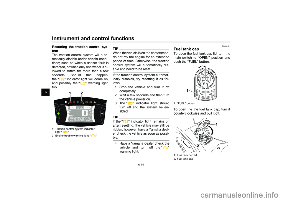
seconds. Should this happen,
the “ ” indicator light will come on,
and possibly the “ ” warning light,
too.
TIPWhen the vehicle is on the centerstand,
do not rev the engine for an extended
period of time. Otherwise, the traction
control system will automatically dis-
able and need to be reset.If the traction control system automat-
ically disables, try resetting it as fol-
lows. 1. Stop the vehicle and turn it off completely.
2. Wait a few seconds and then turn the vehicle power on.
3. The Ž indicator light should turn off and the system be en-
abled.TIPIf the Ž indicator light remains on
after resetting, the vehicle may still be
ridden; however, have a Yamaha deal-
er check the vehicle as soon as possi-
ble.4. Have a Yamaha dealer check thevehicle and turn off the Ž
warning light.
EAUN2571
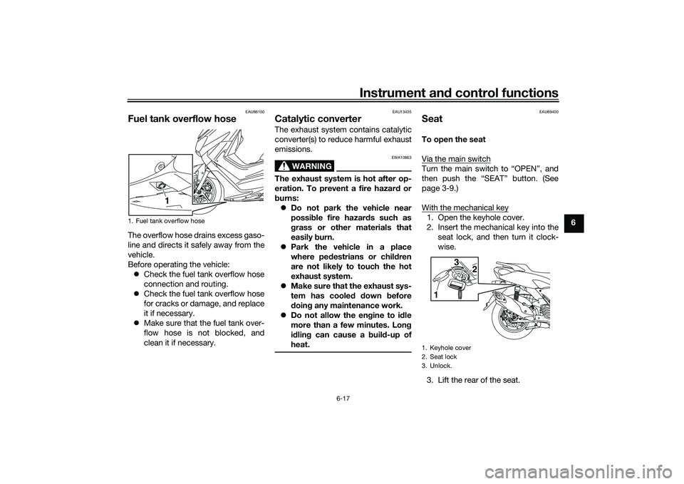
Fuel tank capTo open the fuel tank cap lid, turn the
main switch to “OPEN” position and
push the “FUEL” button.
To open the the fuel tank cap, turn it
counterclockwise and pull it off.
1. Traction control system indicator light “ ”
2. Engine trouble warning light “ ”
1
2
1. “FUEL” button
1. Fuel tank cap lid
2. Fuel tank cap
1
1
2
UBBDE0E0.book Page 14 Wednesday, June 2, 2021 2:57 PM
Page 49 of 114

Instrument and control functions
6-15
6
To install the fuel tank cap, turn it
clockwise until the “ ” mark is facing
forward. Close the fuel tank cap lid.
WARNING
EWA10132
Make sure that the fuel tank cap is
properly installed
before ri din g.
Leakin g fuel is a fire hazar d.
EAU13213
FuelMake sure there is sufficient gasoline in
the tank.
WARNING
EWA10882
Gasoline an d gasoline vapors are
extremely flammab le. To avoid fires
an d explosions an d to re duce the
risk of injury when refueling , follow
these instructions.1. Before refueling, turn off the en- gine and be sure that no one is sit-
ting on the vehicle. Never refuel
while smoking, or while in the vi-
cinity of sparks, open flames, or
other sources of ignition such as
the pilot lights of water heaters
and clothes dryers.
2. Do not overfill the fuel tank. Stop filling when the fuel reaches the
bottom of the filler tube. Because
fuel expands when it heats up,
heat from the engine or the sun
can cause fuel to spill out of the
fuel tank. 3. Wipe up any spilled fuel immedi-
ately. NOTICE: Immediately
wipe off spille d fuel with a clean,
d ry, soft cloth, since fuel may
d eteriorate painte d surfaces or
plastic parts.
[ECA10072]
4. Be sure to securely close the fuel tank cap.
WARNING
EWA15152
Gasoline is poisonous an d can
cause injury or death. Han dle gaso-
line with care. Never siphon gasoline
b y mouth. If you shoul d swallow
some gasoline or inhale a lot of g as-
oline vapor, or get some gasoline in
your eyes, see your doctor imme di-
1. “ ” mark
2. Fuel tank cap
1 2
1. Fuel tank filler tube
2. Maximum fuel level
1
2
UBBDE0E0.book Page 15 Wednesday, June 2, 2021 2:57 PM
Page 51 of 114

Instrument and control functions
6-17
6
EAU86150
Fuel tank overflow hoseThe overflow hose drains excess gaso-
line and directs it safely away from the
vehicle.
Before operating the vehicle:
Check the fuel tank overflow hose
connection and routing.
Check the fuel tank overflow hose
for cracks or damage, and replace
it if necessary.
Make sure that the fuel tank over-
flow hose is not blocked, and
clean it if necessary.
EAU13435
Catalytic converterThe exhaust system contains catalytic
converter(s) to reduce harmful exhaust
emissions.
WARNING
EWA10863
The exhaust system is hot after op-
eration. To prevent a fire hazar d or
b urns:
Do not park the vehicle near
possi ble fire hazar ds such as
g rass or other materials that
easily burn.
Park the vehicle in a place
where pe destrians or chil dren
are not likely to touch the hot
exhaust system.
Make sure that the exhaust sys-
tem has cooled down before
d oin g any maintenance work.
Do not allow the en gine to id le
more than a few minutes. Lon g
i d lin g can cause a buil d-up of
heat.
EAU89400
SeatTo open the seat
Via the main switchTurn the main switch to “OPEN”, and
then push the “SEAT” button. (See
page 3-9.)
With the mechanical key1. Open the keyhole cover.
2. Insert the mechanical key into the seat lock, and then turn it clock-
wise.
3. Lift the rear of the seat.
1. Fuel tank overflow hose
1
1. Keyhole cover
2. Seat lock
3. Unlock.
1 3
2
UBBDE0E0.book Page 17 Wednesday, June 2, 2021 2:57 PM
Page 94 of 114

Periodic maintenance an d a djustment
9-31
9
EAUN2261
Vehicle li ghtsThis model is equipped with LED lights
for headlights, auxiliary lights and
brake/tail light. If a light does not come
on, check the fuse and then have a
Yamaha dealer check the vehicle.NOTICE
ECA16581
Do not affix any type of tinted film or
stickers to the head light lens.
EAU43054
Replacin g a front turn si gnal
li g ht bul b1. Place the vehicle on the center-
stand.
2. Remove the turn signal light bulb socket (together with the bulb) by
turning it counterclockwise.
3. Remove the burnt-out bulb by pulling it out. 4. Insert a new bulb into the socket.
5. Install the socket (together with
the bulb) by turning it clockwise.
1. Headlight (high beam)
2. Headlight (low beam)
3. Auxiliary light
2
3
1
1. Turn signal light bulb socket
1
1. Turn signal light bulb
1
UBBDE0E0.book Page 31 Wednesday, June 2, 2021 2:57 PM
Page 95 of 114

Periodic maintenance an d a djustment
9-32
9
EAU67320
Replacin g a rear turn si gnal
lig ht bul b1. Open the seat. (See page 6-17.)
2. Remove the grab bar by removing
the bolts.
3. Remove the taillight cover by re- moving the screws. 4. Remove the turn signal light bulb
socket (together with the bulb) by
turning it counterclockwise.
5. Remove the burnt-out bulb by pulling it out. 6. Insert a new bulb into the socket.
7. Install the socket (together with
the bulb) by turning it clockwise.
8. Install the taillight cover by install- ing the screws.
9. Install the grab bar by installing the bolts, and then tightening them to
the specified torque.1. Grab bar
2. Bolt1
2
1. Taillight cover
2. Screw
1. Turn signal light bulb socket1 2
1
1. Turn signal light bulb
1
UBBDE0E0.book Page 32 Wednesday, June 2, 2021 2:57 PM
Page 100 of 114

Periodic maintenance an d a djustment
9-37
9
EAU86420
En gine overheatin g
WARNING
EWAT1041
Do not remove the ra diator cap when the en gine an d ra diator are hot. Scal din g hot flui d an d steam may be
b lown out un der pressure, which coul d cause serious injury. Be sure to wait until the en gine has cooled .
Place a thick ra g, like a towel, over the ra diator cap, an d then slowly rotate the cap counterclockwise to the
d etent to allow any resi dual pressure to escape. When the hissin g soun d has stoppe d, press d own on the cap
while turnin g it counterclockwise, an d then remove the cap.TIPIf coolant is not available, tap water can be temporarily used instead, provided that it is changed to the recommended cool-
ant as soon as possible.
Wait until the
engine has cooled.
Check the coolant level in the
reservoir and radiator.
The coolant level
is OK.The coolant level is low.
Check the cooling system
for leakage.
Have a Yamaha dealer checkand repair the cooling system.Add coolant. (See TIP.)
Start the engine. If the engine overheats again,
have a
Yamaha dealer check
and repair the cooling system.
There is
leakage.
There is
no leakage.
UBBDE0E0.book Page 37 Wednesday, June 2, 2021 2:57 PM
Page 112 of 114

13-1
13
IndexAABS ....................................................... 6-12
ABS warning light ................................... 6-2
Acceleration and deceleration ................ 8-3
Activating the Stop and Start System .... 4-1
Air filter and V-belt case air filter
elements ............................................. 9-16
App Connect icon ................................... 6-4BBattery .................................................. 9-28
Brake fluid, changing ............................ 9-24
Brake fluid level, checking .................... 9-23
Brake lever, front .................................. 6-11
Brake lever, rear.................................... 6-11
Brake levers, lubricating ....................... 9-25
Braking.................................................... 8-3CCables, checking and lubricating ......... 9-25
Canister................................................. 9-11
Care ...................................................... 10-1
Catalytic converter ................................ 6-17
CCU (Communication Control Unit) ....... 5-1
Centerstand and sidestand, checking and lubricating .................... 9-26
Clock....................................................... 6-5
Coolant ................................................. 9-15
Coolant temperature meter .................... 6-5DData recording, vehicle ......................... 12-2
Diagnostic connector............................ 12-2
Dimmer switch ...................................... 6-10
Display units, switching .......................... 6-4EEmergency mode.................................. 9-38 Engine break-in ...................................... 8-1
Engine oil and oil strainer ..................... 9-11
Engine overheating ............................... 9-37
Engine serial number ............................ 12-1
FFinal transmission oil ............................ 9-13
Front and rear brake lever free play,
checking............................................. 9-21
Front and rear brake pads, checking ... 9-22
Front fork, checking ............................. 9-27
Fuel ....................................................... 6-15
Fuel consumption, tips for reducing ...... 8-3
Fuel meter .............................................. 6-4
Fuel tank cap ........................................ 6-14
Fuel tank overflow hose ....................... 6-17
Fuses, replacing ................................... 9-29HHandlebar switches .............................. 6-10
Hazard switch....................................... 6-10
Helmet holders ..................................... 6-18
High beam indicator light ....................... 6-1
Horn switch .......................................... 6-10IIdentification numbers .......................... 12-1
Ignition circuit cut-off system ............... 6-22
Incoming call indicator light ................... 6-3
Incoming notification indicator light ....... 6-3
Indicator lights and warning lights ......... 6-1KKey, handling of smart and mechanical keys................................... 3-3MMain switch ............................................ 3-7
Maintenance and lubrication, periodic ... 9-3 Maintenance,
emission control system .......................9-2
Malfunction indicator light (MIL)..............6-1
Matte color, caution ..............................10-1
Menu switch..........................................6-11
Model label ...........................................12-1
Multi-function display .............................6-6
Multi-function meter unit .........................6-3
OOperating range of the smart key system ..................................................3-2PPanels, removing and installing ..............9-7
Parking ....................................................8-4
Part locations ..........................................2-1
Power outlet ..........................................6-21
Precautions when using the Stop and Start System .........................4-3SSafe-riding points....................................1-5
Safety information ...................................1-1
Seat .......................................................6-17
Shock absorber assemblies,
adjusting .............................................6-20
Sidestand ..............................................6-22
Smart key ................................................3-4
Smart key battery, replacing ...................3-6
Smart key system ...................................3-1
Smart key system indicator light.............6-2
Smart key system, troubleshooting ......9-33
Smartphone battery level meter..............6-4
Spark plug, checking ..............................9-9
Special features ......................................5-1
Specifications .......................................11-1
UBBDE0E0.book Page 1 Wednesday, June 2, 2021 2:57 PM