fuse YAMAHA NMAX 155 2021 Owners Manual
[x] Cancel search | Manufacturer: YAMAHA, Model Year: 2021, Model line: NMAX 155, Model: YAMAHA NMAX 155 2021Pages: 114, PDF Size: 10.93 MB
Page 9 of 114

Table of contents
Checking and lubricating the
throttle grip and cable ................9-25
Lubricating the front and rear brake levers ........................9-25
Checking and lubricating the
centerstand and sidestand ........9-26
Checking the front fork..................9-27
Checking the steering ...................9-27
Checking the wheel bearings ........9-28
Battery ...........................................9-28
Replacing the fuses .......................9-29
Vehicle lights .................................9-31
Replacing a front turn signal light bulb ....................................9-31
Replacing a rear turn signal light bulb ....................................9-32
Troubleshooting ............................9-33
Troubleshooting chart ...................9-36
Emergency mode .........................9-38
Motorcycle care an d stora ge ........10-1
Matte color caution .......................10-1
Care ...............................................10-1
Storage ..........................................10-3
Specifications ..................................11-1
Consumer information ...................12-1
Identification numbers ...................12-1
Diagnostic connector ....................12-2
Vehicle data recording ..................12-2 In
dex ................................................ 13-1
UBBDE0E0.book Page 2 Wednesday, June 2, 2021 2:57 PM
Page 17 of 114

Description
2-2
2
EAU10421
Right view
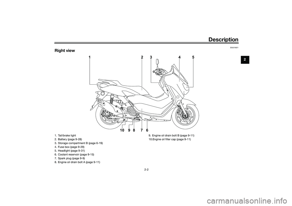
1
10 9 8 7 623 4 5
1. Tail/brake light
2. Battery (page 9-28)
3. Storage compartment B (page 6-19)
4. Fuse box (page 9-29)
5. Headlight (page 9-31)
6. Coolant reservoir (page 9-15)
7. Spark plug (page 9-9)
8. Engine oil drain bolt A (page 9-11)
9. Engine oil drain bolt B (page 9-11)
10.Engine oil filler cap (page 9-11)
UBBDE0E0.book Page 2 Wednesday, June 2, 2021 2:57 PM
Page 55 of 114

Instrument and control functions
6-21
6
EAUN2161
Power outlet This model is equipped with a 12V DC
power outlet.NOTICE
ECAN0140
Do not use the power outlet when
the en gine is off, an d d o not exceed
the specified electrical load ; other-
wise the fuse may blow or the b at-
tery may d ischarge.
When washin g the vehicle, do not di-
rect hi gh-pressure washers at the
power outlet area.
To use the power outlet 1. Turn the vehicle power off.
2. Remove the power outlet cap.
3. Turn the accessory off.
4. Insert the accessory plug into the power outlet.
5. Turn the vehicle power on and start the engine.
6. Turn the accessory on.TIPWhen finished riding, turn off the ac-
cessory and disconnect it from the
power outlet, and then install the cap.
WARNING
EWAN0050
To prevent electrical shock or short-
circuitin g, install the cap when the
power outlet is not in use.
1. Power outletMaximum electrical loa d:
12 W (1A)1
1. Power outlet cap1
UBBDE0E0.book Page 21 Wednesday, June 2, 2021 2:57 PM
Page 92 of 114

Periodic maintenance an d a djustment
9-29
9 battery tends to discharge more quick-
ly if the vehicle is equipped with op-
tional electrical accessories.
NOTICE
ECA16522
To char
ge a VRLA (Valve Re gulate d
Lea d Aci d) battery, a special (con-
stant-volta ge) battery char ger is re-
quired . Using a conventional b attery
char ger will damag e the b attery.To store the b attery
1. If the vehicle will not be used for more than one month, remove the
battery, fully charge it, and then
place it in a cool, dry place.
NOTICE: When removin g the
b attery, be sure to turn the main
switch off, then disconnect the
ne gative lead before discon-
nectin g the positive lea d.
[ECA16304]
2. If the battery will be stored for
more than two months, check it at
least once a month and fully
charge it if necessary.
3. Fully charge the battery before in- stallation. NOTICE: When install-
in g the b attery, be sure to turn
the main switch off, then con- nect the positive lead
before
connectin g the ne gative lea d.
[ECA16842]
4. After installation, make sure that
the battery leads are properly con-
nected to the battery terminals.NOTICE
ECA16531
Always keep the b attery charged .
Storin g a d ischar ged battery can
cause permanent battery damag e.
EAUN2581
Replacin g the fusesThe fuse boxes, which contain the fus-
es for the individual circuits, are locat-
ed under panel C. (See page 9-7.)1. Fuse box
1
UBBDE0E0.book Page 29 Wednesday, June 2, 2021 2:57 PM
Page 93 of 114

Periodic maintenance an d a djustment
9-30
9
If a fuse is blown, replace it as follows. 1. Turn off the electrical circuit in question, and then turn off the
main switch.
2. Remove the panel C. (See page 9-7.) 3. Remove the blown fuse, and then
install a new fuse of the specified
amperage. WARNING! Do not
use a fuse of a hi gher ampera ge
ratin g than recommen ded to
avoi d causin g extensive dam-
a g e to the electrical system an d
possi bly a fire.
[EWA15132]
4. Turn the main switch on, and then
turn on the electrical circuit in
question to check if the device op-
erates.TIPIf the fuse immediately blows again,
have a Yamaha dealer check the elec-
trical system.5. Install the panel C. (See page 9-7.)
1. Signaling system fuse
2. Terminal fuse 1
3. Smart key system fuse
4. ABS motor fuse
5. ABS solenoid fuse
6. Spare fuse
7. Fuel injection system fuse
8. Backup fuse
9. Main fuse
10.Ignition fuse
11.Headlight fuse
12.ABS control unit fuse1
6
2
3
4
5
7
8
9
11
12
610
Specified
fuses:
Main fuse: 30.0 A
Terminal fuse 1:
5.0 A
Headlight fuse: 7.5 A
Signaling system fuse: 7.5 A
Ignition fuse:
7.5 A
Smart key system fuse: 2.0 A
ABS motor fuse: 30.0 A
Fuel injection system fuse:
7.5 A
ABS solenoid fuse: 15.0 A
ABS control unit fuse: 2.0 A
Backup fuse:
7.5 A
UBBDE0E0.book Page 30 Wednesday, June 2, 2021 2:57 PM
Page 94 of 114

Periodic maintenance an d a djustment
9-31
9
EAUN2261
Vehicle li ghtsThis model is equipped with LED lights
for headlights, auxiliary lights and
brake/tail light. If a light does not come
on, check the fuse and then have a
Yamaha dealer check the vehicle.NOTICE
ECA16581
Do not affix any type of tinted film or
stickers to the head light lens.
EAU43054
Replacin g a front turn si gnal
li g ht bul b1. Place the vehicle on the center-
stand.
2. Remove the turn signal light bulb socket (together with the bulb) by
turning it counterclockwise.
3. Remove the burnt-out bulb by pulling it out. 4. Insert a new bulb into the socket.
5. Install the socket (together with
the bulb) by turning it clockwise.
1. Headlight (high beam)
2. Headlight (low beam)
3. Auxiliary light
2
3
1
1. Turn signal light bulb socket
1
1. Turn signal light bulb
1
UBBDE0E0.book Page 31 Wednesday, June 2, 2021 2:57 PM
Page 112 of 114

13-1
13
IndexAABS ....................................................... 6-12
ABS warning light ................................... 6-2
Acceleration and deceleration ................ 8-3
Activating the Stop and Start System .... 4-1
Air filter and V-belt case air filter
elements ............................................. 9-16
App Connect icon ................................... 6-4BBattery .................................................. 9-28
Brake fluid, changing ............................ 9-24
Brake fluid level, checking .................... 9-23
Brake lever, front .................................. 6-11
Brake lever, rear.................................... 6-11
Brake levers, lubricating ....................... 9-25
Braking.................................................... 8-3CCables, checking and lubricating ......... 9-25
Canister................................................. 9-11
Care ...................................................... 10-1
Catalytic converter ................................ 6-17
CCU (Communication Control Unit) ....... 5-1
Centerstand and sidestand, checking and lubricating .................... 9-26
Clock....................................................... 6-5
Coolant ................................................. 9-15
Coolant temperature meter .................... 6-5DData recording, vehicle ......................... 12-2
Diagnostic connector............................ 12-2
Dimmer switch ...................................... 6-10
Display units, switching .......................... 6-4EEmergency mode.................................. 9-38 Engine break-in ...................................... 8-1
Engine oil and oil strainer ..................... 9-11
Engine overheating ............................... 9-37
Engine serial number ............................ 12-1
FFinal transmission oil ............................ 9-13
Front and rear brake lever free play,
checking............................................. 9-21
Front and rear brake pads, checking ... 9-22
Front fork, checking ............................. 9-27
Fuel ....................................................... 6-15
Fuel consumption, tips for reducing ...... 8-3
Fuel meter .............................................. 6-4
Fuel tank cap ........................................ 6-14
Fuel tank overflow hose ....................... 6-17
Fuses, replacing ................................... 9-29HHandlebar switches .............................. 6-10
Hazard switch....................................... 6-10
Helmet holders ..................................... 6-18
High beam indicator light ....................... 6-1
Horn switch .......................................... 6-10IIdentification numbers .......................... 12-1
Ignition circuit cut-off system ............... 6-22
Incoming call indicator light ................... 6-3
Incoming notification indicator light ....... 6-3
Indicator lights and warning lights ......... 6-1KKey, handling of smart and mechanical keys................................... 3-3MMain switch ............................................ 3-7
Maintenance and lubrication, periodic ... 9-3 Maintenance,
emission control system .......................9-2
Malfunction indicator light (MIL)..............6-1
Matte color, caution ..............................10-1
Menu switch..........................................6-11
Model label ...........................................12-1
Multi-function display .............................6-6
Multi-function meter unit .........................6-3
OOperating range of the smart key system ..................................................3-2PPanels, removing and installing ..............9-7
Parking ....................................................8-4
Part locations ..........................................2-1
Power outlet ..........................................6-21
Precautions when using the Stop and Start System .........................4-3SSafe-riding points....................................1-5
Safety information ...................................1-1
Seat .......................................................6-17
Shock absorber assemblies,
adjusting .............................................6-20
Sidestand ..............................................6-22
Smart key ................................................3-4
Smart key battery, replacing ...................3-6
Smart key system ...................................3-1
Smart key system indicator light.............6-2
Smart key system, troubleshooting ......9-33
Smartphone battery level meter..............6-4
Spark plug, checking ..............................9-9
Special features ......................................5-1
Specifications .......................................11-1
UBBDE0E0.book Page 1 Wednesday, June 2, 2021 2:57 PM