ECO mode YAMAHA R6 RACE 2022 Owners Manual
[x] Cancel search | Manufacturer: YAMAHA, Model Year: 2022, Model line: R6 RACE, Model: YAMAHA R6 RACE 2022Pages: 112, PDF Size: 4.06 MB
Page 24 of 112
Instrument and control functions
4-5
4
EAU73931
Drive mo de switch “MODE”
See page 3-1 for an explanation of the
drive mode.
EAU4939G
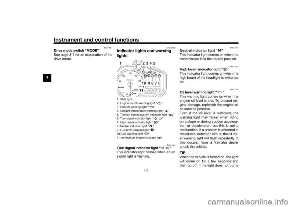
In dicator li ghts an d warnin g
li g hts
EAU11022
Turn si gnal in dicator li ght “ ”
This indicator light flashes when a turn
signal light is flashing.
EAU11061
Neutral in dicator li ght “ ”
This indicator light comes on when the
transmission is in the neutral position.
EAU11081
Hi gh beam in dicator li ght “ ”
This indicator light comes on when the
high beam of the headlight is switched
on.
EAU11259
Oil level warnin g li ght “ ”
This warning light comes on when the
engine oil level is low. To prevent en-
gine damage, replenish the engine oil
as soon as possible.
Even if the oil level is sufficient, the
warning light may flicker when riding
on a slope or during sudden accelera-
tion or deceleration, but this is not a
malfunction. If a problem is detected in
the oil level detection circuit, the oil lev-
el warning light will flash repeatedly. If
this occurs, have a Yamaha dealer
check the vehicle.TIPWhen the vehicle is turned on, the light
will come on for a few seconds and
then go off. If the light does not come
1. Shift light
2. Engine trouble warning light Ž
3. Oil level warning light Ž
4. Coolant temperature warning light Ž
5. Traction control system indicator light Ž
6. Turn signal indicator light Ž
7. High beam indicator light Ž
8. Neutral indicator light Ž
9. Fuel level warning light Ž
10.ABS warning light Ž
11.Immobilizer system indicator light
234510
9
8
7
6
11
1
ABS
UBN6EBE0.book Page 5 Tuesday, October 19, 2021 8:35 AM
Page 27 of 112
Instrument and control functions
4-8
4
3. If the engine starts, turn it off, and
try starting the engine with the
standard keys.
4. If one or both of the standard keys do not start the engine, take the
vehicle and all 3 keys to a Yamaha
dealer to have the standard keys
re-registered.
EAU3904H
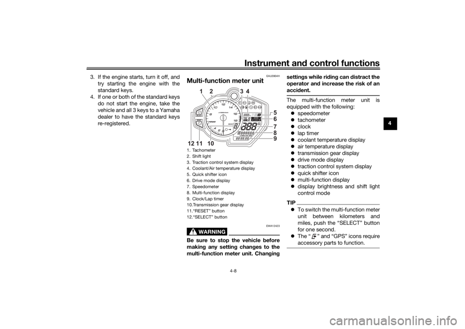
Multi-function meter unit
WARNING
EWA12423
Be sure to stop the vehicle before
makin g any settin g chan ges to the
multi-function meter unit. Chan gin g settin
gs while ri din g can d istract the
operator an d increase the risk of an
acci dent.
The multi-function meter unit is
equipped with the following:
speedometer
tachometer
clock
lap timer
coolant temperature display
air temperature display
transmission gear display
drive mode display
traction control system display
quick shifter icon
multi-function display
display brightness and shift light
control modeTIPTo switch the multi-function meter
unit between kilometers and
miles, push the “SELECT” button
for one second.
The “ ” and “GPS” icons require
accessory parts to function.
1. Tachometer
2. Shift light
3. Traction control system display
4. Coolant/Air temperature display
5. Quick shifter icon
6. Drive mode display
7. Speedometer
8. Multi-function display
9. Clock/Lap timer
10.Transmission gear display
11.“RESET” button
12.“SELECT” button
65789
2
3
4
10
11
12
1
UBN6EBE0.book Page 8 Tuesday, October 19, 2021 8:35 AM
Page 30 of 112
Instrument and control functions
4-11
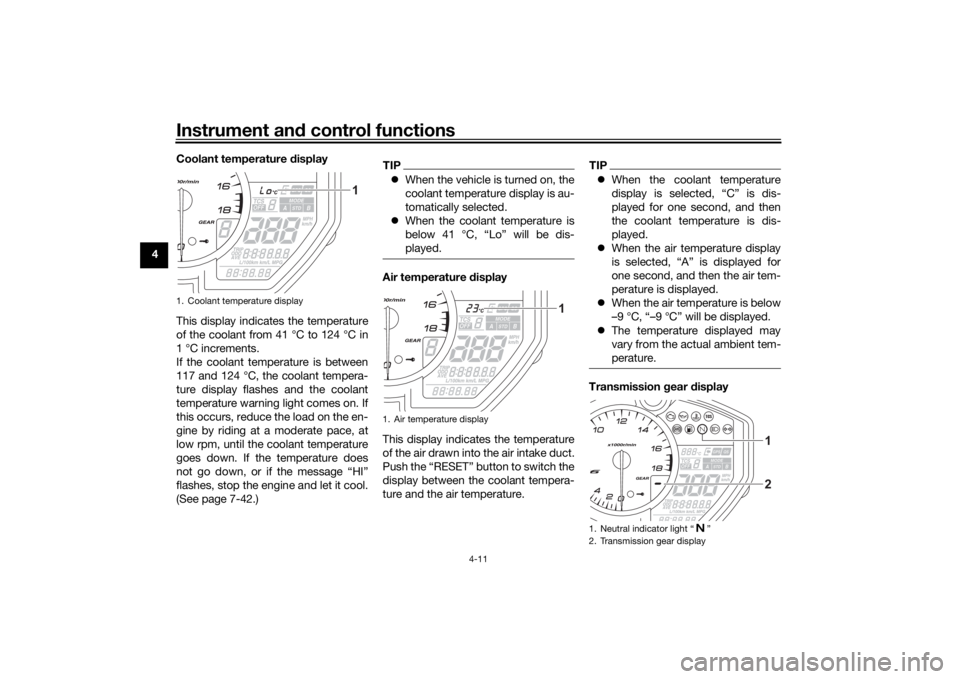
4 Coolant temperature
display
This display indicates the temperature
of the coolant from 41 °C to 124 °C in
1 °C increments.
If the coolant temperature is between
117 and 124 °C, the coolant tempera-
ture display flashes and the coolant
temperature warning light comes on. If
this occurs, reduce the load on the en-
gine by riding at a moderate pace, at
low rpm, until the coolant temperature
goes down. If the temperature does
not go down, or if the message “HI”
flashes, stop the engine and let it cool.
(See page 7-42.)
TIP When the vehicle is turned on, the
coolant temperature display is au-
tomatically selected.
When the coolant temperature is
below 41 °C, “Lo” will be dis-
played.Air temperature d isplay
This display indicates the temperature
of the air drawn into the air intake duct.
Push the “RESET” button to switch the
display between the coolant tempera-
ture and the air temperature.
TIP When the coolant temperature
display is selected, “C” is dis-
played for one second, and then
the coolant temperature is dis-
played.
When the air temperature display
is selected, “A” is displayed for
one second, and then the air tem-
perature is displayed.
When the air temperature is below
–9 °C, “–9 °C” will be displayed.
The temperature displayed may
vary from the actual ambient tem-
perature.Transmission gear display
1. Coolant temperature display
1
1. Air temperature display
1
1. Neutral indicator light
Page 34 of 112
Instrument and control functions
4-15
4 When using kilometers, this figure is
shown in liters. When using miles, this
figure is shown in gallons.
To reset the total fuel used display,
push the “RESET” button for one sec-
ond.
TIPAfter the total fuel used display is reset,
has traveled a sufficient distance.Display
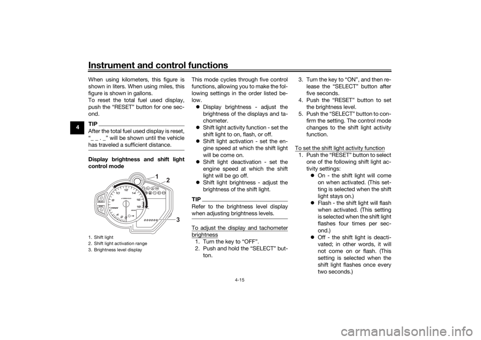
bri ghtness an d shift li ght
control mo de This mode cycles through five control
functions, allowing you to make the fol-
lowing settings in the order listed be-
low.
Display brightness - adjust the
brightness of the displays and ta-
chometer.
Shift light activity function - set the
shift light to on, flash, or off.
Shift light activation - set the en-
gine speed at which the shift light
will be come on.
Shift light deactivation - set the
engine speed at which the shift
light will be go off.
Shift light brightness - adjust the
brightness of the shift light.
TIPRefer to the brightness level display
when adjusting brightness levels.To adjust the display and tachometerbrightness1.
2.
ton. 3.
five seconds.
4. the brightness level.
5. firm the setting. The control mode
changes to the shift light activity
function.
To set the shift light activity function
1. one of the following shift light ac-
tivity settings: On - the shift light will come
on when activated. (This set-
ting is selected when the shift
light stays on.)
Flash - the shift light will flash
when activated. (This setting
is selected when the shift light
flashes four times per sec-
ond.)
Off - the shift light is deacti-
vated; in other words, it will
not come on or flash. (This
setting is selected when the
shift light flashes once every
two seconds.)
1. Shift light
2. Shift light activation range
3. Brightness level display
1
2
3
UBN6EBE0.book Page 15 Tuesday, October 19, 2021 8:35 AM
Page 54 of 112

Operation and important rid ing points
6-1
6
EAU15952
Read the Owner’s Manual carefully to
become familiar with all controls. If
there is a control or function you do not
understand, ask your Yamaha dealer.
WARNING
EWA10272
Failure to familiarize yourself with
the controls can lead to loss of con-
trol, which coul d cause an acci dent
or injury.
EAU73452
TIPThis model is equipped with: a lean angle sensor. This sensor
stops the engine in case of a turn-
over. In this case, turn the main
switch off and then on. Failing to
do so will prevent the engine from
starting even though the engine
will crank when pushing the start
switch.
an engine auto-stop system. The
engine stops automatically if left
idling for 20 minutes. If the engine
stops, simply push the start
switch to restart the engine.
EAU79944
Startin g the en gineThe ignition circuit cut-off system will
enable starting when:
the transmission is in the neutral
position or
the transmission is in gear, the
sidestand is up, and the clutch le-
ver is pulled.
To start the engine1. Turn the main switch on and set the engine stop switch to the run
position.
2. Confirm the indicator and warning light(s) come on for a few sec-
onds, and then go off. (See page
4-5.)TIPDo not start the engine if the en-
gine trouble warning light or the oil
level warning light remains on.
The ABS warning light should
come on and stay on until the ve-
hicle reaches a traveling speed of
10 km/h (6 mi/h).
UBN6EBE0.book Page 1 Tuesday, October 19, 2021 8:35 AM
Page 55 of 112

Operation and important ri din g points
6-2
6
NOTICE
ECA24110
If a warnin g or in dicator li ght does
not work as d escribed a bove, have a
Yamaha dealer check the vehicle.3. Shift the transmission into neutral.
4. Push the start switch “ ” to crank
the engine with the starter.
Release the start switch when the
engine starts, or after 5 seconds.
Wait 10 seconds before pressing
the switch again to allow battery
voltage to restore.NOTICE
ECA11043
For maximum en gine life, never ac-
celerate har d when the en gine is
col d!
EAU77401
Shiftin gShifting gears lets you control the
amount of engine power available for
starting off, accelerating, climbing hills,
etc. The gear positions are shown in
the illustration.TIPTo shift the transmission into the
neutral position ( ), press the
shift pedal down repeatedly until it
reaches the end of its travel, and
then slightly raise it.
This model is equipped with a
quick shift system. (See page 3-4.)
NOTICE
ECA23990
Even with the transmission in
the neutral position, d o not
coast for lon g period s of time
with the en gine off, an d d o not
tow the motorcycle for lon g d is-
tances. The transmission is
properly lu bricated only when
the en gine is runnin g. Ina de-
quate lu brication may d amage
the transmission.
Except when upshiftin g with the
quick shift system, always use
the clutch while chan gin g g ears
to avoi d d amag ing the en gine,
transmission, an d drive train,
which are not d esigne d to with-
stan d the shock of forced shift-
in g.
EAU85370
To start out an d accelerate
1. Pull the clutch lever to disengage the clutch.
2. Shift the transmission into first gear. The neutral indicator light
should go out.
1. Gear positions
2. Shift pedal
2
1
1
N 2 3
4
5
6
UBN6EBE0.book Page 2 Tuesday, October 19, 2021 8:35 AM
Page 104 of 112
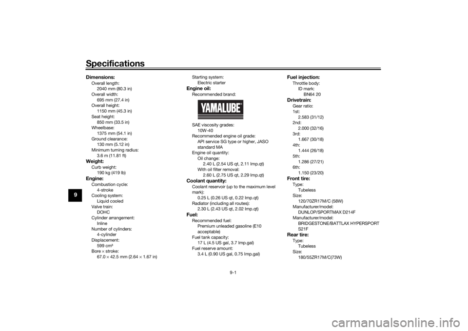
Specifications
9-1
9
Dimensions:Overall length:2040 mm (80.3 in)
Overall width:
695 mm (27.4 in)
Overall height: 1150 mm (45.3 in)
Seat height: 850 mm (33.5 in)
Wheelbase:
1375 mm (54.1 in)
Ground clearance: 130 mm (5.12 in)
Minimum turning radius: 3.6 m (11.81 ft)Wei ght:Curb weight:
190 kg (419 lb)Engine:Combustion cycle:
4-stroke
Cooling system: Liquid cooled
Valve train: DOHC
Cylinder arrangement:
Inline
Number of cylinders: 4-cylinder
Displacement: 599 cm³
Bore × stroke:
67.0 × 42.5 mm (2.64 × 1.67 in) Starting system:
Electric starter
Engine oil:Recommended brand:
SAE viscosity grades:
10W-40
Recommended engine oil grade:
API service SG type or higher, JASO
standard MA
Engine oil quantity:
Oil change: 2.40 L (2.54 US qt, 2.11 Imp.qt)
With oil filter removal:
2.60 L (2.75 US qt, 2.29 Imp.qt)Coolant quantity:Coolant reservoir (up to the maximum level
mark):0.25 L (0.26 US qt, 0.22 Imp.qt)
Radiator (including all routes): 2.30 L (2.43 US qt, 2.02 Imp.qt)Fuel:Recommended fuel:Premium unleaded gasoline (E10
acceptable)
Fuel tank capacity: 17 L (4.5 US gal, 3.7 Imp.gal)
Fuel reserve amount: 3.4 L (0.90 US gal, 0.75 Imp.gal)
Fuel injection:Throttle body:ID mark: BN64 20Drivetrain:Gear ratio:
1st:2.583 (31/12)
2nd:
2.000 (32/16)
3rd: 1.667 (30/18)
4th: 1.444 (26/18)
5th:
1.286 (27/21)
6th: 1.150 (23/20)Front tire:Type:
Tubeless
Size: 120/70ZR17M/C (58W)
Manufacturer/model: DUNLOP/SPORTMAX D214F
Manufacturer/model:
BRIDGESTONE/BATTLAX HYPERSPORT
S21FRear tire:Type:Tubeless
Size: 180/55ZR17M/C(73W)
UBN6EBE0.book Page 1 Tuesday, October 19, 2021 8:35 AM
Page 106 of 112

Consumer information
10-1
10
EAU53562
Id entification num bersRecord the vehicle identification num-
ber, engine serial number, and the
model label information in the spaces
provided below. These identification
numbers are needed when registering
the vehicle with the authorities in your
area and when ordering spare parts
from a Yamaha dealer.
VEHICLE IDENTIFICATION NUMBER:
ENGINE SERIAL NUMBER:
MODEL LABEL INFORMATION:
EAU26401
Vehicle i dentification num ber
The vehicle identification number is
stamped into the steering head pipe.
Record this number in the space pro-
vided.TIPThe vehicle identification number is
used to identify your motorcycle and
may be used to register your motorcy-
cle with the licensing authority in your
area.
EAU26442
En gine serial num ber
The engine serial number is stamped
into the crankcase.
EAU26521
Mo del la bel
1. Vehicle identification number
1
1. Engine serial number
1. Model label
1
1
UBN6EBE0.book Page 1 Tuesday, October 19, 2021 8:35 AM
Page 107 of 112

Consumer information
10-2
10
The model label is affixed to the frame
under the passenger seat. (See page
4-22.) Record the information on this
label in the space provided. This infor-
mation will be needed when ordering
spare parts from a Yamaha dealer.
EAU69910
Dia
gnostic connectorThe diagnostic connector is located as
shown.
EAU85300
Vehicle data recor din gThis model’s ECU stores certain vehi-
cle data to assist in the diagnosis of
malfunctions and for research, statisti-
cal analysis and development purpos-
es.
Although the sensors and recorded
data will vary by model, the main data
points are:
Vehicle status and engine perfor-
mance data
Fuel-injection and emission-relat-
ed data
This data will be uploaded only when a
special Yamaha diagnostic tool is at-
tached to the vehicle, such as when
maintenance checks or service proce-
dures are performed.
Vehicle data uploaded will be handled
appropriately according to the follow-
ing Privacy Policy.
Privacy Policy
1. Diagnostic connector
1
https://www.yamaha-motor.eu/eu/
privacy/privacy-policy.aspx
UBN6EBE0.book Page 2 Tuesday, October 19, 2021 8:35 AM
Page 109 of 112

11-1
11
Index
AABS....................................................... 4-18
ABS warning light ................................... 4-7
Air filter element.................................... 7-20
Auxiliary DC connector ......................... 4-29BBattery .................................................. 7-35
Brake and clutch levers, checking
and lubricating ................................... 7-32
Brake and shift pedals, checking and lubricating........................................... 7-32
Brake fluid, changing............................ 7-28
Brake fluid level, checking.................... 7-27
Brake lever............................................ 4-17
Brake lever free play, checking ............ 7-25
Brake light switches ............................. 7-26
Brake pedal .......................................... 4-17CCables, checking and lubricating ......... 7-31
Canister ................................................ 7-14
Care ........................................................ 8-1
Catalytic converter ............................... 4-22
Clutch lever........................................... 4-16
Clutch lever free play, adjusting ........... 7-24
Coolant ................................................. 7-19
Coolant temperature warning light ......... 4-6
Cowlings and panels, removing and installing ............................................... 7-9DData recording, vehicle......................... 10-2
Diagnostic connector ........................... 10-2
Dimmer switch........................................ 4-4
D-mode (drive mode).............................. 3-1
Drive chain, cleaning and lubricating ... 7-30 Drive chain slack .................................. 7-29
Drive mode switch ................................. 4-5
EEngine break-in ...................................... 6-3
Engine idling speed, checking ............. 7-20
Engine oil and oil filter cartridge........... 7-15
Engine overheating .............................. 7-42
Engine serial number ........................... 10-1
Engine trouble warning light .................. 4-6
EXUP system ....................................... 4-28FFront and rear brake pads, checking ... 7-26
Front fork, adjusting ............................. 4-24
Front fork, checking ............................. 7-34
Fuel ...................................................... 4-19
Fuel level warning light........................... 4-6
Fuel tank cap........................................ 4-19
Fuel tank overflow hose ....................... 4-21
Fuses, replacing ................................... 7-36HHandlebar switches ............................... 4-3
Hazard switch ........................................ 4-4
High beam indicator light ....................... 4-5
Horn switch ............................................ 4-4IIdentification numbers ......................... 10-1
Ignition circuit cut-off system .............. 4-30
Immobilizer system ................................ 4-1
Immobilizer system indicator light ......... 4-7
Indicator lights and warning lights ......... 4-5LLicense plate light bulb, replacing ....... 7-38MMain switch/steering lock ...................... 4-2Maintenance and lubrication, periodic ... 7-5
Maintenance, emission control
system .................................................. 7-3
Matte color, caution................................ 8-1
Model label ........................................... 10-1
Multi-function meter unit ........................ 4-8
NNeutral indicator light ............................. 4-5OOil level warning light .............................. 4-5PParking.................................................... 6-4
Part locations.......................................... 2-1
Pass switch............................................. 4-4QQuick shifter............................................ 3-4RRear view mirrors .................................. 4-23SSafety information................................... 1-1
Seats ..................................................... 4-22
Shifting.................................................... 6-2
Shift light ................................................. 4-7
Shift pedal............................................. 4-17
Shock absorber assembly, adjusting ... 4-26
Sidestand.............................................. 4-29
Sidestand, checking and lubricating .... 7-33
Spark plugs, checking .......................... 7-13
Special features ...................................... 3-1
Specifications ......................................... 9-1
Starting the engine ................................. 6-1
Steering, checking ................................ 7-34
Stop/Run/Start switch ............................ 4-4
Storage ................................................... 8-3
UBN6EBE0.book Page 1 Tuesday, October 19, 2021 8:35 AM